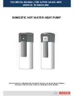
background image


DOMESTIC HOT WATER HEAT PUMP


This document is confidential and restricted to exclusive use by the official technical 

assistance of Bosch in the countries of destination of this product. 


TECHNICAL MANUAL FOR AFTER SALES AND  

SERVICE TECHNICIANS 

Summary of Contents for AquaEco HP270-1 E C

Page 1: ...EAT PUMP This document is confidential and restricted to exclusive use by the official technical assistance of Bosch in the countries of destination of this product TECHNICAL MANUAL FOR AFTER SALES AND SERVICE TECHNICIANS ...

Page 2: ...EASUREMENTS 19 4 COMPONENTS OVERVIEW 23 4 1 COMPRESSOR 23 4 2 FILTERS AND DRIERS 27 4 3 EXPANSION VALVE 27 4 4 PRESSURE CONTROL BY NORMALLY CLOSED PRESSURE SWITCH 28 4 5 EVAPORATOR 29 4 6 CONDENSER 30 5 HUMAN MACHINE INTERFACE HMI 31 6 MAINTENANCE AND PREVENTIVE ACTIONS 37 6 1 CORROSION 37 6 2 WATER QUALITY 37 6 3 TYPES OF SCALE 39 6 4 MAINTENANCE ACTIVITIES FOR TECHNICIANS 40 7 TROUBLESHOOTING 47...

Page 3: ...10º 35º Yes Compress 3000 DWFO HP 270 1E 1 FOV S FR DK GR 7736500991 Bosch 10º 35º No Compress 3000 DWFO HP 270 1E 0 FOV S FR 7736500781 Buderus 5º 35º Yes Logatherm WPT 270 I S HP 270 1E 1 FIV S DE BE PL CZ AT 7736500890 Buderus 5º 35º No Logatherm WPT 270 I HP 270 1E 0 FIV S DE BE PL AT 7736501013 Buderus 10º 35º Yes Logatherm WPT 270 A S HP 270 1E 1 FOV S DE BE PL CZ IT AT 7736501014 Buderus 10...

Page 4: ...exchanger heating the water stored in a tank a b Pict 1 a Refrigeration Unit and b Storage Tank with coil The engine absorbs energy Qc from a cold source heat absorbed from air and expels energy Qh to a hot destination heat delivered to water while Work W is done in the refrigerator circuit electrical supply The work done is ensured by an electrical plug that supplies electricity to the compressor...

Page 5: ...nal integrated coil for external energy source as integration with existent standing or wall hung boiler or even solar energy installation Picture 3 shows the internal constitution and main components 1 Fan and evaporator group 2 Compressor 3 Condenser Plate Heat Exchanger 4 Filter dryer and expansion valve 5 Water circulation pump 6 Storage tank 7 Electrical resistance for backup 8 Internal coil ...

Page 6: ... the heat pump is higher than 3 which corresponds to an efficiency of 300 Pict 5 Generic overview of the 4 stages of gas 1 Liquid refrigerant R 134a boils at a low temperature in the evaporator The output is a low temperature and low pressure vapour 2 Vapour pressure and temperature increase in the compressor The electric motor is used to drive vapour through the compressor and increase vapour tem...

Page 7: ... on the module Follow instructions from picture 6 existent in the sticker on the back of the tank Pict 6 Disassembling of top cover In front of the appliance and protected by an EPP front panel fixed to the tank with 4 magnets it is possible to find the magnesium anode and the electric resistance for backup Pict 7 Front view of the heat pump ...

Page 8: ...ines that all magnesium anodes must be checked at least each two years considering normal conditions ensuring a visual control The acceptable water quality to the heat pump storage tank requires Water pH between 6 5 and 9 5 Hardness range 3 0 ºdH Depending on the appliance production date the anodes can have a measured terminal or not Those which do not have a measurements terminal need a direct v...

Page 9: ...ct 10 Anodic current measurement with an anode tester or a multimeter Anyway a visual inspection is strongly recommended every 2 year in order to identify an eventual start of a crack in a part of the anode or eventually the calc deposition over the magnesium anode surface which will decrease the anodic current as well but will also disable the protection function of the anode The visual inspectio...

Page 10: ...the electric resistance of 2kW immerged in the storage tank This component has a safety function set at 90ºC limiting the temperature from an external source solar boiler etc to 80ºC Pict 12 Electric Resistance 2 kW Pict 13 Bipolar thermostat interfaces Pict 14 Check voltage supply o the thermostat Temperature adjustment ...

Page 11: ... to increase robustness of the tank in the models with coil the electric heater of the models HP 270 1E 1 with coil is from was isolated Spare part will is available as isolated electric heater for models with and without coil a Resistor 560Ω b Dielectric insulation tank electric heater Picture 17 Isolated electric heater Attention Resistor connection Picture 17 a is essential to ensure function a...

Page 12: ...ture in the tank for the external heat source a pocket for external sensor is available and adapted to the available fixation systems of sensors in TT ensuring the correct contact with the tank Pict 18 Storage tank and example of external sensor fixation system to pocket 3 Module A routine maintenance agreement should be taken with a licensed service person or organisation In addition end users sh...

Page 13: ...riously out of level repair or replace the base of the unit Refrigerant o Check the operation of the air on air off with a digital thermometer o Check pipe joints for refrigerant leakage with a bubble solution Electrical o Check terminals and connections clean and tight if necessary o Check the voltage and current Service checklist o Provide the end user with a filled service checklist after each ...

Page 14: ...igerant leaves the evaporator in the vapour state and during the refrigerant condensation there is a heat generation which will be transferred in this case to the domestic water that flows in the condenser Pict 20 General components overview in the module 5ºC 35ºC As the temperature of the available water is always higher than the one from boiling refrigerant in the evaporator the refrigerant in t...

Page 15: ...e vaporized refrigerant flows through the compressor where the pressure of the vaporized refrigerant is raised to a point at which it can be condensed by some relatively warm fluid water at normal conditions The compressor removes the refrigerant vapour and this creates such a low pressure in the evaporator that the evaporation temperature is kept below the surrounding temperature After being comp...

Page 16: ...ºC with exception of the defrosting process which is done through a solenoid valve activated by the control unit depending on the temperature measured by the NTCs assembled in the evaporator fins and sensing the air temperature which will be detailed further in this manual Pict 22 General components overview in the module 10ºC 35ºC ...

Page 17: ...al fan operation 230 V Compressor Suppliers Mitsubishi model KB 134 VFN Highly model WHP01900BSV Specification from supplier 2 kW of heating capacity Thermal protection included temperature limiter opens at 160ºC closes at 70ºC Condenser Supplier Swep Specifications from supplier Maximum pressure 50 bar Pump Supplier Wilo ZRS12 2 3KV Specifications from supplier 3 speed pump maximum pressure 10 ba...

Page 18: ...y tube length of 1 m MOP at 15ºC TEV with built in orifice of 2 mm bulb Ø of 12 mm internal equalization and fixed superheating setting Specifications from supplier Thermostatic expansion valve for serial produced systems Max ambient temperature 100ºC Max bulb temperature 140ºC Evaporating temp 15 40ºC Inlet ODF 3 8 Outlet ODF 1 2 Pressure Switch Supplier Danfoss Low Pressure Switch LPS PS 45 bar ...

Page 19: ...0ºC 35ºC Component Characteristics A5 B1 X X Air NTC R 10k 25ºC 10000 Ω A11 B2 X X Hot Water NTC R 10k 25ºC 10000 Ω A13 B3 X X Cold Water NTC R 10k 25ºC 10000 Ω A19 B15 X Fins NTC R 8k 25ºC 8400 Ω A12 B10 X X Pump Wilo 230 196 253 Vac 50 47 5 52 5 Hz 19 32 48 W 0 10 0 15 0 21 A A4 X X Condenser Swep type A14 X X Filter Drier PS 11 43 bar Scheme A Scheme B ...

Page 20: ... Highly B6 X X Compressor Capacitor 17 μF 15 μF Mitsubishi Highly B8 X X Compressor Protection Bimetallic thermal switch open at 160ºC close at 70ºC B4 X X Supply Cable to control unit 230 V 10 15 50 Hz B5 X X High Pressure Switch Temp 60ºC Opening pressure 27 bar Closing pressure 20 bar B9 X X Low Pressure Switch Temp 5ºC Opening pressure 0 7 bar Closing pressure 2 4 bar A10 B12 X X Electric resi...

Page 21: ...alue to check and identify each proper function These NTC sensors are a 10kΩ type In case their minimum and maximum operation values are below or above the expected temperature resistance values the display will present the correspondent error code The NTC sensor in the fins is 8kΩ with characteristic listed on table 3 Temperature ºC NTC Resistance Ω 10kΩ type fins NTC Resistance Ω 8kΩ air cold ho...

Page 22: ...53 1752 75 1598 1481 80 1384 1258 85 1202 1072 90 1048 917 95 916 788 100 804 680 105 707 588 Table 3 NTC characteristic Pict 25 Electrical cables connection on HMI Pict 26 Cable connections overview Fan Capacitor Fan Connection Capacitor Connection Pump Connection Electrical Supply connection ...

Page 23: ...d to the system size The compressor is filled with special oil for lubrication purposes this is an important checking point for servicing Lubrication Almost all refrigerant compressors contain oil which lubricates the compressor moving parts and forms seals between these moving parts during the compression The oil is important to achieve high efficiency in the compressor but it affects negatively ...

Page 24: ...onality nevertheless the HMI will detect if compressor is running Cables and cover protection have clear identification of the different connections R Main electro valve S Auxiliary electro valve C Common Pict 28 Compressor electrical connections and thermal protection Checking Continuity and Resistance Ω Between C R 0 Mitsubishi 4 7 Ω Highly 5 84 Ω Between C S 0 Mitsubishi 8 2 Ω Highly 7 62 Ω Bet...

Page 25: ...sis 0 R chassis 0 Attention In case of continuity the compressor is defected Pict 30 Testing of compressor Thermal Protection This function is ensured by a bimetallic temperature limiter which opens its contact when high temperature T 160ºC 10ºC is reached during operation Pict 31 Testing of thermal protection limiter ...

Page 26: ...T 70ºC Pict 32 Functional position After any intervention ensure correct cover protection assembly Pict 33 Cover of electrical elements from compressor Capacitor of Compressor Pict 34 Discharging capacitor In case of check capacitor discharge electric charge with a resistance of 20k and 2W Not OK OK 0Ω Pict 35 Capacitor testing ...

Page 27: ...igerant to boil and create flash gas which will disrupt the operation of the expansion valve Pict 36 Filter Drier cut model for internal view 4 3 Expansion valve The expansion valve has two main functions Controlling the amount of refrigerant entering the evaporator Maintaining the pressure difference between the condenser high pressure and the evaporator low pressure The pressure difference creat...

Page 28: ...res pressures in order to have an efficient system Pressure gauges accessible to the technicians are permanently installed to allow monitoring compressor suction low pressure side and discharging pressures high pressure side These kinds of connections use throttle valves that prevent against gauge fluctuation when readings are to be taken In both sides high and low pressure the high and low pressu...

Page 29: ... valve group 4 5 Evaporator The evaporator is used for the heat transfer between the air surrounding and the refrigerant in the system The refrigerant entering the evaporator under pressure expands i e it converts from a liquid to a gaseous state and thus evaporates in the evaporator The cooled air produced by this process is discharged to the environment via the large surface of the evaporator Up...

Page 30: ...compression in the compressor The hot refrigerant gas flows into the compressor thereby dissipating heat to the other side of the plate As it cools the refrigerant pressure falls and the refrigerant state changes from gaseous to liquid Soldered flat pipe condensers have high capacity and less volume Domestic Hot Water Side Secondary circuit Refrigeration side Primary circuit ...

Page 31: ...r shall be periodically cleaned in order to avoid obstruction Pict 43 Plates of the heat exchanger and counter flow representation 5 Human Machine Interface HMI User manual must be used to verify functions and active parameters For the service mode following instructions should be considered The control unit has a standby consumption of 3W ...

Page 32: ...ir actions 5 35 10 35 Parameter Description Active Symbol Unit X X 0d Set point temperature of hot water on control unit ºC X X 1d Temperature of Hot Water NTC in the top of the tank ºC X X 2d Temperature of cold water NTC between pump and condenser ºC X X 3d Temperature of air in circulation NTC between air admission and evaporator ºC X 4d Temperature of the evaporator NTC in the fins ºC X X 5d C...

Page 33: ... air temperature is out of the specified range the appliance automatically activates the electrical back up without leaving the Combi mode One hour after the warning display HOT or COLD has appeared the appliance checks the air temperature again and if it is within the range values turns again to heat pump operation The control loop is done every hour after electrical back up emergency operation E...

Page 34: ... switch in the back of HP Error in memory Stand by mode 1 Error Mode no yes 1 Stand by mode HMI actuation LCD Backlight ON Active Operation Mode LCD Backlight OFF after 15 sec without any selection Temperature of the Tank Clock Day Function Temperature Selection Temperature Blinks until confirmation with OK button Temperature remain previous one after 10 sec without any selection ...

Page 35: ...ion before versions HPAF0211 10ºC models and HPAF0311 5ºC models Conditions for legionela disinfection TTop T set 3ºC and Tbottom 60ºC TTop T set or Tbottom 62ºC TBottom 4ºC Start Up Stop Module Anti Freeze Water pump runs for 2 minute TTop 5ºC Tank Anti Freeze Water Pump ON Electrical heater ON till TTop 8ºC TBottom 2ºC Module Anti Freeze Water pump runs for 1 minute TTop 20ºC and TBottom 5ºC Tan...

Page 36: ... for more than 60 min and Tair Tfins 3 5ºC for more than 1 min Full mode until Ttop 60ºC Legionela stops when TTop 70ºC or TBottom 60ºC or time in Legi 24h Electric Heater mode until Ttop 70ºC Water Pump OFF Compressor OFF Fan ON during 10 min Tbottom 20ºC defrost every 90 min Tbottom 35ºC defrost every 150 min Tbottom 60ºC defrost every 240 min 1 st step Pre Gas Defrost 2 nd step Gas Defrost Fan ...

Page 37: ...ds that fail to penetrate in flange joints and under deposits on the steel surface General corrosion This is a kind of deterioration distributed more or less uniformly over a surface This type of corrosion is more predictable than pitting a General copper corrosion b Pitting corrosion in stainless steel Pict 46 Examples of corrosion Unfavourable environment may lead to the increase of the risk of ...

Page 38: ...deposits River and lake surface water The concentration of scale forming salts is usually fairly low However there may be amounts of solids ranging from salts and soil particles to leave Some type of pre treatment is necessary particularly to control biological activity Sea water Is not recommended because of the corrosive action of very high chloride concentrations Check water quality and recomme...

Page 39: ...orrosion is a very complex process influenced by many different factors in combination this table is a considerable simplification which should be taken in consideration 6 3 Types of scale Calcium carbonate CaCO3 can be formed when calcium or bicarbonate alkalinity is present An increase in heat and or an increase in pH will cause precipitation of calcium carbonate Calcium Sulfate CaSO4 is 50 time...

Page 40: ...dequate procedure for the treatment Chemical cleaning is the use of chemicals to dissolve or loosen deposits from process equipment and piping Removal is uniform and generally at a low cost Step 1 Chemical cleaning solutions Using organic acids are weaker than mineral acids but safer to material and handling The organic acids can be used in combination with other chemicals to remove the scale comp...

Page 41: ...defective insulation Heating element Cleaning of calc deposition inspection of integrity Table 6 Resume of main maintenance actions The main connections are through thread connection with washer however and for the connections of the flexible hose with o ring connection the lubricant L 641 part nr 8 709 918 413 Water lubricant for water valve connections must be used a b Pict 47 a O ring lubricant...

Page 42: ...cture 47 shows one example of a recommended pump from the supplier Sanit Available models KalkMax 500 or 800 Pict 48 Sanit Kalkmax pump According to the supplier of the condenser SWEP with this type of components it can be used a liquid such as Kaloxi This cleaning compound especially developed to dissolve and remove the internal deposition of scale forming salts in water supplied systems is caust...

Page 43: ...and open hot water tap to take out pressure from the top of the heat pump Remove connection in the top of the condenser plate heat exchanger to allow the outlet of the water and then remove the connection in the bottom Pict 50 Unscrew water connections to the condenser plate heat exchanger Connect flexible connection of the pump already with the liquid ...

Page 44: ...direction of the water The direction can be defined in the pump on the correspondent lever as shown in picture 51 Pict 52 Flexible hose of descaling Leave the pump in operation for some minutes to remove lime scale After cleaning process make circulation with clean water to eliminate vestiges of the acid solution In the models with manual air purge depending on production date ensure its correct p...

Page 45: ...f the evaporator and the consequent energy transfer to the refrigerant gas Pict 54 Detail of the fins and 3 passages evaporator cut model Pict 55 Damaged fins in the evaporator The alignment of the fins can be done with an adequate brush and the cleaning process with a vacuum cleaner During maintenance the surface of the evaporator can be sprayed with the same available solution in the market as f...

Page 46: ...on of the circuit Parameter Value for 5ºC to 35ºC and 10ºC to 35ºC Comments Type of refrigerant R134a GWP 1300 ODP 0 00 Ebullition temperature 26 1 ºC Gas charge 375 g Suction pressure Temperature 3 5 bar 10ºC outlet of evaporator inlet to compressor Discharge pressure Temperature 8 bar 50ºC outlet of compressor inlet to condenser Internal pressure Temperature 3 5 bar 4ºC Inlet of evaporator outle...

Page 47: ...ort circuit Check cable sensor and measure NTC value 3 NTC has values out of its borders Measure NTC sensor value Code E04 Warning Code self reset error Temperature in storage tank higher than 80ºC Detected by the hot water NTC in the top of the tank 1 Heat Pump storage tank connected to a solar installation Reduce maximum temperature of storage tank in the solar controller 2 Heat Pump storage tan...

Page 48: ...time 6 Water flow through condenser is too low Check eventual calc or debris deposition in the sanitary side of the condenser plate heat exchanger and clean it 7 Water shortage 12h 8 After a repair and or R134 replacement Too much refrigerant inside circuit max 375 g Rework charging procedure Code E10 Lock Out Error Fault in the electrical backup resistance by current sensor in control unit 1 Acti...

Page 49: ...cing the complete expansion valve 7 Dry filter is saturated and block refrigerant flow filter outlet is much colder than inlet Replace filter Code HOT Warning Code Temperature of air admission higher than 35ºC 1 Self Reset error after normal temperature conditions are reached Code COLD Warning Code Temperature of air admission lower than 5ºC or 10ºC according model 1 Self Reset error after normal ...

Page 50: ...rigeration system is opened and serviced in order to avoid reading the saturation point The bulb position must be ensured in the top position after the evaporator to allow a correct reading and a proper functionality of the expansion valve In case of HMI replacement respect and assemble the NTCs in the correct position to avoid wrong temperature detection For the analysis of common failures even w...

Page 51: ...osses in cooling capacity This should be measured in the suction side of the compressor pressure gauge available By measuring the temperature in the evaporator and knowing the calculated pressure drop we can check actual pressure drop Check the amount of superheat A high level of superheating could indicate that the expansion valve is not releasing enough floe to the evaporator or vice versa Check...

Page 52: ...n conditions If the temperature difference is higher than the design conditions the water flow rate has been reduced Check the amount of sub cooling Too much sub cooling will block the heat transfer surface from the condensing process and thus increase the condensing pressure This may indicate that the system has been overcharged Release refrigerant charge until a reasonable value 2k 5k is achieve...

Page 53: ...rigerant recovery recycling reclamation or charge in system type of refrigerants already handled level and training needs Specific tools for R134a availability Refrigerant circuit parameters suction pressure at evaporator outlet compressor inlet use pressure gauge connection available suction temperature discharge pressure at compressor outlet condenser inlet use pressure gauge available discharge...

Page 54: ...port Pict 61 Digital refrigeration analyser example from Testo Nevertheless service pressure gauges should be calibrated regularly and be of good quality The data obtained from the service will have some accuracy and will depend greatly on the human factor They should therefore be used with caution and compared with design data of the system to find and analyse discrepancies A thermometer with a s...

Page 55: ...ere it may cause severe damage due to its incompressibility It may also contaminate the lubricants The level of superheating should be kept to a minimum to minimize both the work to be done by the compressor and the necessary heat transfer surface in the evaporator Sub cooling of the refrigerant gas In the fundamental process the liquid leaving the condenser was just on the saturation line for liq...

Page 56: ...ng temperature and the temperature of the gas coming from the evaporator The evaporating temperature is determined with a pressure gauge and the temperature of the gas is measured with a digital thermometer Takes place in the evaporator and indicates the gas temperature raise superheat after it has changed the into gas state Attention The more refrigerant the expansions valve lets flow into the ev...

Page 57: ... pressure and superheat is oscillating Note High and Low pressure switch in the refrigeration circuit will activate when pressures are out of range Adjusting the superheat In this type of appliances the adjustment of the superheat is made by opening or closing of the expansion valve Closing the expansion valve superheat increase Less refrigerant is let into the evaporator causing a lower evaporati...

Page 58: ...resent in the bottom of the condenser The higher level the higher the sub cooling becomes Theoretically we can sub cool the liquid down to the temperature level of the incoming heat carrier In practice this is not possible when the level reaches a certain level the condensing pressure rises Adjusting the sub cooling First make sure that the superheat is properly adjusted The adjustment of the sub ...

Page 59: ...gas Depending on the type of machine other tools can be needed and the list should be adapted to the available equipment in the countries Material Tool Function Notes Fire extinguisher Bottle to be used for security purposes in case of fire Safety Equipment Accessories for handling and protection of the technician during working process in refrigerant equipment Portable lights To ensure correct wo...

Page 60: ...ts of refrigeration operation pressures and temperatures for the purpose of refrigerant transfer and for system evacuation a service gauge manifold is used 1 Manifold body 2 Manifold body 3 Sight glass for refrigerant flow 4 Low pressure valve 5 Vacuum pump valve 6 High pressure valve 7 Valve connection for charging cylinder or recovery unit 8 Hose connection 1 4 male flare SAE 9 Vacuum hose conne...

Page 61: ...liver in the adequate entities for recycling process Vacuum pump To make vacuum to the refrigeration system after repairs and parts replacement preparing the unit to a new charge of new gas and ensuring the absence of humidity in the interior 1 Double stage vacuum pump 2 Solenoid valve 3 Handle with exhaust of purged air 4 Vacuum gauge relative 5 Oil level sight glass 6 Oil mist filter 7 3 8 hose ...

Page 62: ...bacteria s in the air flow way spray to retire dirtiness grass and other elements from fins and not aggressive for aluminum Gas leakage detectors Electronic leak detector for HC refrigerants Sensitivity less than 50 ppm Propane Iso Butane Methane 1 Flexible metal probe with sensor 2 Keypad Reversible ratchet handle To remove magnesium anode and replace it Anode Control Tester only for measurable t...

Page 63: ...lding function for easy reading 1 Ampere measuring clamp 2 LCD display 3 Measurement selector 4 Test leads Digital multimeter Tests batteries capacitors and resistors components as well continuity s in sensors etc 1 Measurement selector 2 Test leads Anemometer and thermometer Air velocity measurement for air systems 1 Vane sensor with integrated thermometer 2 Measuring device for temperature and a...

Reviews: