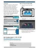
background image

ADS 525X Quick Start Guide

(en-US)

Summary of Contents for ADS 525X

Page 1: ...ADS 525X Quick Start Guide en US ...

Page 2: ...nce with the instructions may cause harmful interference to radio communica tions To reduce risk of injury charge only Bosch Automotive Service Solutions Inc supplied rechargeable batter ies for the ADS 625 product with the supplied charger Other types of batteries may burst causing injury to persons and property damage Use of an attachment not recommended or sold by the battery charger manufactur...

Page 3: ...ials Diagnostic Information Wiring Diagrams i i Saved Reports Main Menu Diagnostics 1 2 3 4 8 4 5 6 7 11 8 10 9 19 18 22 21 20 24 23 25 17 14 13 12 15 1 Camera Front facing camera 2 Ambient Light Sensor 3 Vehicle Connection Indicator 4 VCI Connection Manager 5 Power Button 6 Volume Up 7 Volume Down 8 Main Menu Functions 9 Recent apps button 10 Home Button 11 Back button 12 Future Use 13 Micro USB ...

Page 4: ... Block and Charging Cord When the handset is turned on the level of battery charge is indicated in the upper right corner of the screen Note It is recommended to keep the scan tool plugged into power supply when not being used For maximum battery life properly power off scan tool when not in use for extended periods ADS 525X is supplied with 2 micro USB power cables and 1 USB power block 2 ft cabl...

Page 5: ...timeout To use again press the power button to wake the tool up This will allow maximum run time while not limiting productivity When the tool is powered up even if it is not being actively used Wi Fi and Bluetooth radios as well as all other necessary hardware are still being powered Battery life is comparable to similar devices when in this state Note It is recommended to keep the scan tool plug...

Page 6: ... Product Carefully read the terms and conditions of this Agreement before using this Software Product Use of this Software Product indicates your acceptance of the following terms and conditions 1 LICENSE Bosch grants you a personal non transferable except as noted in Section 8 Assignment and non exclusive limited license without the right to sublicense to ise the Software Product embedded on this...

Page 7: ... Printer Setup If skipped you may setup a printer later from settings Skip Print test page Printer setup help rt0010 Note This can be completed later by going to Settings located on the Main Menu screen 10 Connect the VCI to the vehicle rt00001 1 2 3 1 OBDII DLC Cable 2 DLC 3 VCI 11 Connect the handset to the VCI Pairing VCI Connection Manager Icon Definitions Icon that will display when user is c...

Page 8: ...iring Diagrams i i Saved Reports Main Menu Diagnostics rt0011 d Once VCI Connection Manager icon is selected VCI Connection Manager dialog is displayed listing discovered VCIs e Select Connect next to VCI in the list to pair with it Once VCI Connection Manager icon changes to Connected via Wi Fi the tool is ready to use The handset is now paired to a VCI To use a different VCI in the future repeat...

Page 9: ...ss02876 5 6 7 2 1 3 4 1 Power port used when necessary 2 DLC OBDII cable port 3 Power Indicates the VCI has received power 4 PC Connection Indicates the VCI is communicating with the PC 5 Vehicle Connection Indicates the VCI is communicating with vehicle 6 USB B Port 7 Connection port for future use ...

Page 10: ...epair Source vehicle repair information 5 Diagnostic Information button Provides diagnostic repair and reset information for the selected vehicle 6 Wiring Diagrams button Provides OEM and vehicle specific full color full system wiring diagrams 7 Saved Reports button Access saved vehicle scan reports and data stream recordings 8 Web Browser button Full internet access and shortcuts to repair inform...

Page 11: ...e Guide Video Tutorials Diagnostic Information Wiring Diagrams i i Saved Reports Main Menu Diagnostics See What s New See What s New See What s New See What s New Select Vehicle Make sure the key is ON and Engine is OFF Choose vehicle selection method SEARCH BY VIN Cancel AutoID Manual Selection Recent Vehicles rt0013 1 2 3 4 1 Select AutoID to start to automatically detect the vehicle 2 Select Ma...

Page 12: ...VIN from 1996 2000 Use the information below to understand when Auto ID is best used 2000 2004 some US vehicles may respond to Mode 9 From 2000 2004 it was only used at the OEMs discretion 2005 2007 many US vehicles will respond to Mode 9 From 2000 2007 it was CARB advised but not required 2008 current virtually all US vehicles are required to respond to Mode 9 OBDII Mode 9 was not ARB required un...

Page 13: ...s 4 Data Stream The data stream function shows live sensor and solenoid data streaming from the vehicle ECU electronic control unit 5 All Special Tests Access Special Test Menu 6 Special Tests Shortcut Access to vehicle maintenance tests for specific vehicle systems to provide for recalibration or reset after service 7 Enhanced Vehicle Scan Access to scan all available controllers on the selected ...

Page 14: ...s will activate an indication of LO or if above 15 5 Volts and indication of HI will activate highlighting that the battery or charging system needs attention ss02659 1 2 3 4 1 LED Lamp 2 LED lamp switch 3 Battery cover 4 DLC tool connector with voltmeter Software Updates Software Updates Periodically updates will become available and the user will be notified through a message on the screen To re...

Page 15: ...X4 CONTROL 3 DTC S found 3 DTC S found 3 DTC S found Clear DTCs Refresh Share Save Home Details Details Details rt0015 Connected to 2008 Ford F 150 King Ranch 5 4L Connected 10 22 P0030 Change Vehicle Heated Oxygen Sensor Heater Control Circuit Sensor 1 Description Description Mitchell Diagnostics System Wiring Measures the amount of oxygen in the exhaust gas and sends a corresponding signal to th...

Page 16: ...Bosch Automotive Service Solutions Inc 655 Eisenhower Drive Owatonna MN 55060 USA Phone 1 855 267 2483 Option 1 www boschdiagnostics com 1699502643 Rev B ...

Reviews: