


Summary of Contents for ACS 561
Page 1: ...ACS 561 en Repair instruction A C Service Unit ...
Page 95: ......
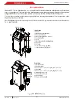
The Bosch ACS 561 is a highly efficient and reliable automotive diagnostic tool designed to assist mechanics and DIY enthusiasts in performing repairs with ease. This user-friendly device provides comprehensive Repair Instructions through a downloadable manual, available for free at manualshive.com. Streamline your repair process and ensure optimal performance for vehicles with the Bosch ACS 561.
Page 1: ...ACS 561 en Repair instruction A C Service Unit ...
Page 95: ......


