Summary of Contents for ACS 251
Page 1: ...ACS 251 en Original instructions A C service unit ...
Page 2: ......
Page 22: ......
Page 23: ......
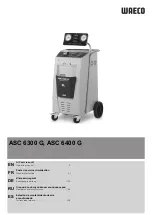
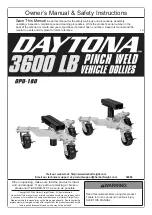
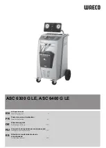
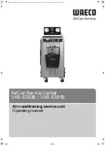
The Bosch ACS 251 is a high-performance air conditioning service unit. Ensure smooth operation with the Original Instructions Manual, available for free download on our website. This comprehensive manual provides step-by-step guidance, allowing users to optimize their experience with the ACS 251. Download the manual at manualshive.com today.
Page 1: ...ACS 251 en Original instructions A C service unit ...
Page 2: ......
Page 22: ......
Page 23: ......