background image

Bosch


Wired Wall Thermostat

For use with Bosch Split-Type Ductless Air Conditioner / Heat Pump 


User Manual

Summary of Contents for 8733953127

Page 1: ...Bosch Wired Wall Thermostat For use with Bosch Split Type Ductless Air Conditioner Heat Pump User Manual ...

Page 2: ...2 Bosch Climate 5000 Series Wired Wall Thermostat User Manual 06 2019 Bosch Thermotechnology Corp Data subject to change ...

Page 3: ...nit 9 5 7 Reattach the Cover of the Wired Wall Thermostat 10 5 8 Installation Guide for Wall Mounted Indoor Unit Only 10 6 Operation Guideline 12 6 1 Set Date and Time 12 6 2 Cooling Heating Fan Operation 12 6 3 Change Fan Speed 12 6 4 Follow Me Function Wall Mounted Indoor Unit Only 13 6 5 Child Lock 13 6 6 Key Pad Tone Setting 13 6 7 F C Selection 13 6 8 Turbo Mode 13 6 9 Decorative Grille Autom...

Page 4: ...r serious injury CAUTION indicates a hazardous situation which if not avoided could result in minor to moderate injury NOTICE is used to address practices not related to personal injury Important information This symbol indicates important information where there is no risk to people or property 2 Remote Controller Specifications IDU Type Wall Mounted Cassette Ducted Model Name BMS WT1 XXX BMS WT2...

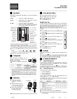
Page 5: ... mode of operation AUTO COOL DRY HEAT FAN 3 FAN Change fan speed AUTO LOW MED HIGH You can not switch the fan speed in AUTO or DRY mode 4 ADJUST Used to adjust setting 5 SWING Adjust louver angle Wall Mounted and Cassette type indoors only 6 TIMER Set up On Off Timer 7 Day schedule 7 DAY OFF DEL Used to skip day during 7 Day scheduling or delete saved set up 8 CONFIRM Used to save setting change 9 ...

Page 6: ... Fan Swing Fan Swing Indicator Left Right Not applicable 8 Fan Swing Fan Swing Indicator Up Down 9 Faceplate Decorative Grille Automatic Lift Function optional accessory required 10 A B Unavailable function in N A 11 Follow Me Follow Me Function Indicator 12 Turbo Turbo Mode On Indicator 13 Fan Speed Fan Speed Indicator Lo Med Hi Auto 14 Temperature Temperature Display 15 Unit ºC ºF Indicator 16 L...

Page 7: ...in 62mm 5 2 Wiring Figure 4 red black yellow brown red black yellow brown Insert of the mainboard CN40 Wire controller Indoor unit mainboard 4 Core Shielded Cable The length is decided by installation For Wall Mounted Indoor Units Install the Adapter Board and the Display Board on the Wall Mounted indoor unit Figure 5 Model BMS WT1 XXX 8733953127 Adapter board Display board 4 core shielding wire T...

Page 8: ...n cable CN40 Do not install the wired wall thermostat where it can be affected by Direct hot or cold air from ducts Drafts or dead spots behind doors and corners Direct sun light contact area 5 3 Remove Front Cover 1 Insert a screwdriver into the slots in the lower part of the wired wall thermostat 2 places Slots 2 Remove the front cover The PCB is mounted in the upper part of the wired controller ...

Page 9: ...rface Over tightening screws may damage back plate of the wired wall thermostat 5 5 Battery Installation 1 Place the battery in the unit and ensure the positive side of the battery is in accordance with the polarity markings Figure 9 2 Set the correct time before operating Batteries in the wired controller can maintain the correct time during a power failure When the power is restored and the disp...

Page 10: ...res Figure 13 Putty Putty Putty Trap Trap Trap 5 7 Reattach the Cover of the Wired Wall Thermostat 1 Avoid clamping during installation Figure 14 5 8 Installation Guide for Wall Mounted Indoor Unit Only 1 Open the front panel of the Wall Mounted Indoor Unit Figure 15 2 Disconnect the wire from the main control board Figure 16 3 Identify the components From left to right display board and adapter b...

Page 11: ...th CN403 from the board and close the cover Figure 18 5 Before mounting back on the front panel remove the display board s screen cover Figure 19 6 Connect 4 pin black to Wired Wall Thermostat Figure 20 7 Connect 8 pin connector from the display board to the IDU Figure 21 8 Place display adapter board on the back of the front panel and close the cover of IDU control box Figure 22 ...

Page 12: ...ime in 1 minute increments Figure 26 ex Monday 11 20 5 The setting is complete after pressing TIMER Figure 27 Timer 6 2 Cooling Heating Fan Operation Ensure the unit is plugged in and power is available 1 Press the power button Figure 28 2 Press Mode to change select desired operation mode Figure 29 Mode 3 Press or to set desired temperature Figure 30 Lower Raise In the FAN mode the setting temper...

Page 13: ...ted Indoor models 6 5 Child Lock 1 Press LOCK for 3 seconds to activate the CHILD LOCK Figure 34 Fan speed Lock 2 Press again for 3 seconds to deactivate 6 6 Key Pad Tone Setting 1 Press Swing and Timer simultaneously for 3 seconds to disable the key pad tone Figure 35 Swing Timer 2 Press both buttons again for 3 seconds to enable the key pad tone 6 7 F C Selection 1 Press Back Turbo and Timer sim...

Page 14: ...trol the lift up and down functions of the grille While grille lifts down press to stop While grille lifts up press to stop Figure 40 Lower Raise 6 10 Swing Function Louver Up Down applicable to Wall mounted and Cassette Indoor models only 1 The louver swings by six degrees every time when the Swing button is pressed 2 Press and hold Swing for 2 seconds to activate auto swing mode Press Swing agai...

Page 15: ...day Schedule 1 Press Timer to select the Week and press Confirm Figure 42 Timer Confirm 2 Press or to select the day of the week and then press CONFIRM Figure 43 Confirm 3 Press and to select the set time The set time mode temperature and fan speed appear on the display Press CONFIRM to enter the setting time process Figure 44 Confirm Up to 8 scheduled events can be set on one day Figure 45 ex Tues...

Page 16: ...d to set the fan speed then press CONFIRM Figure 49 Confirm This setting is unavailable in the AUTO DRY or OFF modes 8 Different schedules can be programmed by repeating steps 3 through 7 6 11 2 Starting Saved 7 Day Schedule To Start Press Timer to select the and then the timer starts automatically Figure 50 Timer To Cancel Press Power to cancel the timer mode Figure 51 The timer mode can also be c...

Page 17: ... the weekly timer Figure 55 Back Turbo 6 To cancel follow the same procedures used for setup The DAY OFF holiday setting is cancelled automatically after the set day has passed 6 12 Copy Existing Schedule A saved schedule can be copied to another day of the week 1 After starting the 7 Day schedule press CONFIRM 2 Press or to select the day of the week Figure 56 Confirm 3 Press COPY the letters CY ...

Page 18: ...8 Press BACK to revert to the 7 Day schedule Figure 60 Back Turbo 6 13 Delete Saved Schedule 1 Activate 7 day schedule and press CONFIRM Figure 61 Confirm 2 Press and to select the day to delete and then press CONFIRM Figure 62 Confirm 3 After selecting the day to be deleted press Day off Del to delete the saved setting Figure 63 Dayoff Del ...

Page 19: ...to set the time After the time is set the timer starts or stops automatically Figure 66 ex Off timer set at 18 00 4 Press Confirm again to finish the settings Figure 67 Confirm 6 14 Set Timer On and Off Function 1 Press Timer to select the Figure 68 Timer 2 Press Confirm and the Clock display flashes Figure 69 Confirm 3 Press and to set the On timer and then press CONFIRM Figure 70 Confirm 4 Press or ...

Page 20: ...United States and Canada Bosch Thermotechnology Corp 65 Grove Street Watertown MA 02472 Tel 866 642 3198 Fax 603 965 7581 www boschheatingandcooling com BTC 769003108 A 06 2019 ...

Reviews: