


Assembly instructions
3 842 358 724/2013-04
Replaces: –
English
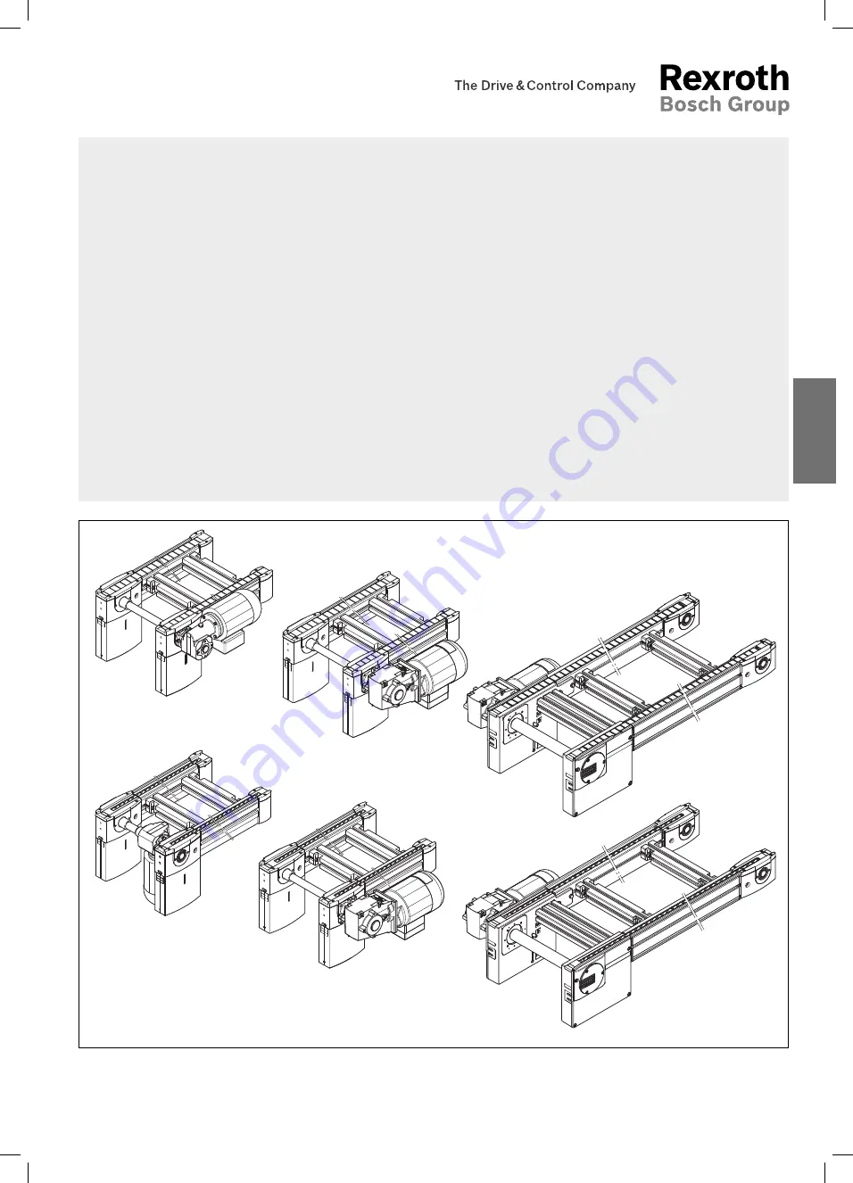
BS 2/C-100
BS 2/C-H
BS 2/R-700
BS 4/R-700
BS 2/R-300
BS 4/R-300
BS 2/R-H
BS 2/R-V-1200
BS 2/C-250
BS 2/C-…, BS 2/R-…
Belt sections
Applies to the following types:
3 842 998 096 , BS 2/R-700
3 842 998 097 , BS 4/R-300
3 842 998 238 , BS 2/R-H
3 842 998 239 , BS 2/C-H
3 842 998 492 , BS 2/R-V-1200
3 842 999 901 , BS 4/R-700
3 842 999 904 , BS 2/R-300
3 842 999 917 , BS 2/C-100
3 842 999 985 , BS 2/C-250
EN
GLISH
358724_2013_04_EN.indd 1
358724_2013_04_EN.indd 1
27.05.2013 13:07:31
27.05.2013 13:07:31


