background image

Motherboard

TUF Z270 

MARK 1

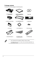
Summary of Contents for PRIME Z270-A Series

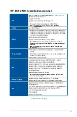
Page 1: ...Motherboard TUF Z270 MARK 1 ...

Page 2: ...respective companies and are used only for identification or explanation and to the owners benefit without intent to infringe Offer to Provide Source Code of Certain Software This product contains copyrighted software that is licensed under the General Public License GPL under the Lesser General Public License Version LGPL and or other Free Open Source Software Licenses Such software in this produ...

Page 3: ...1 1 9 Internal connectors 1 14 Chapter 2 Basic Installation 2 1 Building your PC system 2 1 2 1 1 IO Cover installation 2 1 2 1 2 Motherboard installation 2 3 2 1 3 CPU installation 2 5 2 1 4 CPU heatsink and fan assembly installation 2 7 2 1 5 DIMM installation 2 9 2 1 6 ATX power connection 2 10 2 1 7 SATA device connection 2 10 2 1 8 Front I O connector 2 11 2 1 9 Expansion Card installation 2 ...

Page 4: ...guration 3 17 3 6 6 PCH FW Configuration 3 18 3 6 7 Thunderbolt TM Configuration 3 18 3 6 8 Onboard Devices Configuration 3 19 3 6 9 APM Configuration 3 20 3 6 10 Network Stack Configuration 3 20 3 6 11 HDD SSD SMART Information 3 20 3 6 12 USB Configuration 3 20 3 7 Monitor menu 3 21 3 8 Boot menu 3 21 3 9 Tool menu 3 23 3 9 1 ASUS EZ Flash 3 Utility 3 23 3 9 2 Secure Erase 3 24 3 9 3 ASUS Overcl...

Page 5: ...Installing Serial ATA hard disks 4 2 4 1 3 Intel Rapid Storage Technology in UEFI BIOS 4 2 4 1 4 Intel Rapid Storage Technology Option ROM utility 4 6 4 2 Creating a RAID driver disk 4 10 4 2 1 Creating a RAID driver disk in Windows 4 10 Appendix Notices A 1 ASUS contact information A 5 ...

Page 6: ...your area If you are not sure about the voltage of the electrical outlet you are using contact your local power company If the power supply is broken do not try to fix it by yourself Contact a qualified service technician or your retailer Operation safety Before installing the motherboard and adding devices on it carefully read all the manuals that came with the package Before using the product en...

Page 7: ... installing system components 3 Chapter 3 BIOS Setup This chapter tells how to change system settings through the BIOS Setup menus Detailed descriptions of the BIOS parameters are also provided 4 Chapter 4 RAID Support This chapter describes the RAID configurations Where to find more information Refer to the following sources for additional information and for product and software updates 1 ASUS w...

Page 8: ...lete a task IMPORTANT Instructions that you MUST follow to complete a task NOTE Tips and additional information to help you complete a task Typography Bold text Indicates a menu or an item to select Italics Used to emphasize a word or a phrase Key Keys enclosed in the less than and greater than sign means that you must press the enclosed key Example Enter means that you must press the Enter or Ret...

Page 9: ...6 or dual at x8 x8 mode 1 x PCI Express 3 0 2 0 x16 slot max at x4 mode compatible with PCIe x1 x2 and x4 devices 3 x PCI Express 3 0 2 0 x1 slots VGA Integrated Graphics Processor Intel HD Graphics support Multi VGA output support DisplayPort HDMI port Supports DisplayPort 1 2 with max resolution 4096 x 2304 60Hz Supports HDMI 1 4b with max resolution 4096 x 2160 24Hz Supports Intel InTru 3D Quic...

Page 10: ...oth sound deliver equal quality Impedance sense for front and rear headphone outputs Audio shielding ensures precise analog digital separation and greatly reduced multi lateral interference Internal audio Amplifier to enhance the highest quality sound for headphone and speakers Unique de pop circuit to reduce start up popping noise to audio outputs Premium Japan made audio capacitors provides warm...

Page 11: ... Angel TUF Detective 2 TUF ESD Guards 2 TUF LANGuard MemOK ASUS Features USB BIOS Flashback with USB BIOS Flashback Wizard for EZ BIOS download scheduling TPU with fast tuning EPU AURA Lighting Control and AURA Lighting Effects synchronization with compatible ASUS ROG devices ASUS UEFI BIOS EZ Mode featuring friendly graphics user interface Turbo LAN to experience smooth online gaming with lower p...

Page 12: ... SATA 6 0Gb s connectors 1 x CPU Fan connector 4 pin for both 3 pin DC mode and 4 pin PWM mode CPU coolers control with auto detection support 1 x CPU OPT Fan connector 4 pin 1 x W_Pump header 4 pin 5 x Chassis Fan connectors 4 pin for both 3 pin DC mode and 4 pin PWM mode coolers control 1 x H_AMP_FAN 4 pin for both 3 pin DC mode and 4 pin PWM mode control 1 x Assistant Fan connectors 4 pin 1 x F...

Page 13: ...F3 My Favorites Last Modified log F12 PrintScreen and ASUS DRAM SPD Serial Presence Detect memory information Manageability WfM 2 0 DMI 3 0 WOL by PME PXE Support DVD contents Drivers ASUS Utilities EZ Update Anti virus software OEM version Operating System Support Windows 10 64 bit Windows 8 1 64 bit Windows 7 Windows 8 1 64 bit and Windows 7 32 64 bit are only supported when using 6th Generation...

Page 14: ...tor 1 x CPU Installation Tool 1 x M 2 screw package 1 x Vertical M 2 bracket set 2 x PCIe x16 slot covers 3 x PCIe x1 slot covers 1 x TUF Inside sticker Package contents Check your motherboard package for the following items If any of the above items is damaged or missing contact your retailer The illustrated items above are for reference only Actual product specifications may vary with different ...

Page 15: ...nal Phillips cross screwdriver PC chassis Power supply unit Intel LGA1151 CPU Intel LGA1151 compatible CPU Fan DIMM SATA hard disk drive SATA optical disc drive optional The tools and components in the table above are not included in the motherboard package ...

Page 16: ...xvi ...

Page 17: ...s by the edges to avoid touching the ICs on them Whenever you uninstall any component place it on a grounded antistatic pad or in the bag that came with the component Before you install or remove any component ensure that the ATX power supply is switched off or the power cord is detached from the power supply Failure to do so may cause severe damage to the motherboard peripherals or components 1 1...

Page 18: ... Chapter 1 Product Introduction Chapter 1 Refer to 1 1 9 Internal connectors and 2 3 1 Rear I O connection for more information about rear panel connectors and internal connectors 1 1 2 Motherboard layout ...

Page 19: ...DDR4 DIMM slots 1 5 5 MemOK button 1 10 6 Thermal sensor connectors 2 pin T_SENSOR1 3 1 21 7 USB 3 0 connector 20 1 pin USB3_34 USB3_56 1 16 8 Intel Serial ATA 6 Gb s connectors 7 pin SATA6G_12 SATA 6G_34 SATA 6G_56 1 14 9 System panel connector 20 3 pin PANEL 1 20 10 M 2 sockets M 2_1 M 2_2 1 22 11 Clear RTC RAM jumper 2 pin CLRTC 1 11 12 USB 2 0 connectors 10 1 pin USB1314 USB1112 1 17 13 TPM co...

Page 20: ... socket contacts are not bent Contact your retailer immediately if the PnP cap is missing or if you see any damage to the PnP cap socket contacts motherboard components ASUS will shoulder the cost of repair only if the damage is shipment transit related Keep the cap after installing the motherboard ASUS will process Return Merchandise Authorization RMA requests only if the motherboard comes with t...

Page 21: ...figurations 1 1 4 System memory The motherboard comes with four DDR4 Double Data Rate 4 Quad Inline Memory Modules DIMM slots A DDR4 module is notched differently from a DDR DDR2 or DDR3 module DO NOT install a DDR DDR2 or DDR3 memory module to the DDR4 slot ...

Page 22: ...the dual channel configuration Any excess memory from the higher sized channel is then mapped for single channel operation The default memory operation frequency is dependent on its Serial Presence Detect SPD which is the standard way of accessing information from a memory module Under the default state some memory modules for overclocking may operate at a lower frequency than the vendor marked va...

Page 23: ...ing or removing expansion cards Failure to do so may cause you physical injury and damage motherboard components Slot No Slot Description 1 PCIE 3 0 2 0 x1_1 slot 2 PCIE 3 0 2 0 x16_1 slot 3 PCIE 3 0 2 0 x1_2 slot 4 PCIE 3 0 2 0 x16_2 slot 5 PCIE 3 0 2 0 x1_3 slot 6 PCIE 3 0 2 0 x16_3 slot ...

Page 24: ..._1 shared PCIe X16_2 shared PCIe X16_3 shared PCIe X1_1 shared PCIe X1_2 shared PCIe X1_3 shared SMBUS Controller shared SATA Controller shared Intel LAN I211 shared Intel Lan I219V shared ASMedia USB Controller 2142 shared Intel xHCI shared HD Audio shared VGA configuration PCI Express 3 0 operating mode PCIe 3 0 2 0 x16_1 PCIe 3 0 2 0 x16_2 PCIe 3 0 2 0 x16_3 Single VGA PCIe card x16 single VGA ...

Page 25: ...ckers and gamers who continually change settings to enhance system performance 1 Power on button The motherboard comes with a power on button that allows you to power up or wake up the system The LED near the PCH also lights up when the system is plugged to a power source indicating that you should shut down the system and unplug the power cable before removing or installing any motherboard compon...

Page 26: ...s If the test fails the system reboots and tests the next set of failsafe settings The blinking speed of the DRAM_LED increases indicating different test processes Due to memory tuning requirement the system automatically reboots when each timing set is tested If the installed DIMMs still fail to boot after the whole tuning process the DRAM_LED lights continuously Replace the DIMMs with ones recom...

Page 27: ...s and enter BIOS setup to re enter data Except when clearing the RTC RAM never place a metal object or jumper cap on the CLRTC jumper Placing a metal object or jumper cap will cause system boot failure If the steps above do not help remove the onboard battery and place a metal object or jumper cap again to clear the CMOS RTC RAM data After the CMOS clearance reinstall the battery You do not need t...

Page 28: ...V The CPU Over Voltage jumper allows you to set a higher CPU voltage for a flexible overclocking system depending on the type of the installed CPU To gain more CPU voltage setting insert the jumper to pins 2 3 To go back to its default CPU voltage setting insert the jumper to pins 1 2 ...

Page 29: ...s found the critical component s LED stays lit up until the problem is solved 2 Standby Power LED The motherboard comes with a standby power LED The LED lights up to indicate that the system is ON in sleep mode or in soft off mode This is a reminder that you should shut down the system and unplug the power cable before removing or plugging in any motherboard component The illustration below shows ...

Page 30: ...ed Serial ATA hard disk drives you can create a RAID 0 1 5 and 10 configuration with the Intel Rapid Storage Technology through the onboard Intel Z270 chipset These connectors are set to AHCI Mode by default If you intend to create a Serial ATA RAID set using these connectors set the SATA Mode item in the BIOS to Intel RST Premium With Intel Optane System Acceleration RAID Before creating a RAID s...

Page 31: ...r a chassis mounted front panel audio I O module that supports HD Audio Connect one end of the front panel audio I O module cable to this connector We recommend that you connect a high definition front panel audio module to this connector to avail of the motherboard s high definition audio capability ...

Page 32: ...can enjoy all the benefits of USB 3 0 including faster data transfer speeds of up to 5 Gb s faster charging time for USB chargeable devices optimized power efficiency and backward compatibility with USB 2 0 The USB 3 0 module is purchased separately Ensure to install the related driver to fully use the USB 3 0 ports under Windows 7 The plugged USB 3 0 device may run on xHCI or EHCI mode depending ...

Page 33: ...all the module to a slot opening at the back of the system chassis This USB connector complies with USB 2 0 specification that supports up to 480 Mb s connection speed 4 Thunderbolt header 5 pin TB_HEADER This connector is for the add on Thunderbolt I O card that supports Intel s Thunderbolt Technology allowing you to connect up to six Thunderbolt enabled devices and a DisplayPort enabled display ...

Page 34: ...board components These are not jumpers Do not place jumper caps on the fan connectors Ensure that the CPU FAN cable is securely installed to the CPU fan connector The CPU_FAN connector supports the CPU fan of maximum 1A 12 W fan power The CPU_FAN CHA_FAN and ASST_FAN connectors support the TUF Thermal Radar 2 feature For better Q Fan functions we recommend using 4 pin PWM fans when you connect pow...

Page 35: ...er power output when configuring a system with more power consuming devices The system may become unstable or may not boot up if the power is inadequate If you want to use two or more high end PCI Express x16 cards use a PSU with 1000W power or above to ensure the system stability 7 ATX power connectors 24 pin EATXPWR 8 pin EATX12V These connectors are for ATX power supply plugs The power supply p...

Page 36: ...utton 2 pin PWRSW This connector is for the system power button Pressing the power button turns the system on or puts the system in sleep or soft off mode depending on the operating system settings Pressing the power switch for more than four seconds while the system is ON turns the system OFF Reset button 2 pin RESET This 2 pin connector is for the chassis mounted reset button for system reboot w...

Page 37: ...e network security protect digital identities and ensures platform integrity The TPM module is purchased separately 10 Thermal sensor connectors 2 pin T_SENSOR1 3 These connectors are for the thermistor cable that monitors the temperature of the devices and the critical components inside the motherboard Connect the thermistor cable and place the sensor on the device or the motherboard s component ...

Page 38: ...dules M 2_1 socket supports PCIe 3 0 x4 and SATA mode M Key design and type 2242 2260 2280 22110 PCIe and SATA storage devices M 2_2 socket supports PCIe 3 0 x4 M Key design and type 2242 2260 2280 PCIe storage devices These sockets support IRST Intel Rapid Storage Technology The M 2 SSD module is purchased separately ...

Page 39: ...on and better airflow To install the 40 mm assistant fan 1 Locate and remove the screw on the back I O A then remove the back I O fan cover lid B Keep the screws for later use 2 Position and install the 40 mm assistant fan in an orientation such that the fan draws air into the chassis for optimal heat dissipation and air ventilation 3 Match the two 2 screw holes on the 40 mm assistant fan with the...

Page 40: ... behavior 4 Align and insert the cover lid and the assistant fan assembly into the IO Cover and secure it with the screw that you removed in step 1 Fan cable corner slot Ensure to tuck the fan cable inside the cable corner slot 5 Connect the fan cable connector to the assistant fan ASST_FAN header on the motherboard ...

Page 41: ...1 2 3 Chapter 2 2 1 2 Motherboard installation 1 Install the ASUS Q Shield to the chassis rear I O panel 2 Place the motherboard into the chassis ensuring that its rear I O ports are aligned to the chassis rear I O panel ...

Page 42: ...4 Chapter 2 Basic Installation Chapter 2 3 Place nine screws into the holes indicated by circles to secure the motherboard to the chassis DO NOT overtighten the screws Doing so can damage the motherboard ...

Page 43: ...hapter 2 2 1 3 CPU installation Ensure that you install the correct CPU designed for LGA1151 socket only DO NOT install a CPU designed for LGA1155 and LGA1156 sockets on the LGA1151 socket Top of CPU Bottom of CPU Bottom of CPU ...

Page 44: ...llation Tool for installing the CPU only DO NOT damage or bend the CPU Installation Tool Always firmly hold both sides of the CPU Installation Tool when installing removing or picking up the CPU Installation Tool ASUS will not cover damages resulting from incorrect CPU installation removal incorrect CPU orientation placement or other damages resulting from negligence by the user ...

Page 45: ... 7 Chapter 2 2 1 4 CPU heatsink and fan assembly installation Apply the Thermal Interface Material to the CPU heatsink and CPU before you install the heatsink and fan if necessary To install the CPU heatsink and fan assembly ...

Page 46: ...2 8 Chapter 2 Basic Installation Chapter 2 To uninstall the CPU heatsink and fan assembly ...

Page 47: ...ASUS TUF Z270 MARK 1 2 9 Chapter 2 To remove a DIMM 2 1 5 DIMM installation ...

Page 48: ...2 10 Chapter 2 Basic Installation Chapter 2 2 1 6 ATX power connection Ensure to connect the 8 pin power plug 2 1 7 SATA device connection OR ...

Page 49: ...S TUF Z270 MARK 1 2 11 Chapter 2 2 1 8 Front I O connector To install ASUS Q Connector USB 2 0 AAFP To install USB 2 0 connector To install front panel audio connector USB 3 0 To install USB 3 0 connector ...

Page 50: ...2 12 Chapter 2 Basic Installation Chapter 2 2 1 9 Expansion Card installation To install PCIe x16 cards To install PCIe x1 cards ...

Page 51: ...ASUS TUF Z270 MARK 1 2 13 Chapter 2 2 1 10 M 2 installation OR Supported M 2 type varies per motherboard ...

Page 52: ...OS Flashback button for three seconds until a flashing light appears which indicates that the BIOS Flashback function is enabled 5 Wait until the light goes out indicating that the BIOS updating process is completed DO NOT unplug portable disk power system or use the CLR_CMOS jumper while BIOS update is ongoing otherwise update will be interrupted In case of interruption please follow the steps ag...

Page 53: ...ts TUF Detective 2 only 8 USB 3 0 ports 34 3 USB BIOS Flashback button 9 USB 3 1 Type C port 4 DisplayPort 10 USB 3 1 port 5 Intel LAN port I211 AT 11 Optical S PDIF Out port 6 Intel LAN port I219 V 12 Audio I O ports USB 3 1 3 0 devices can only be used as data storage only We strongly recommend that you connect your devices to ports with matching data transfer rate Please connect your USB 3 0 de...

Page 54: ...then steady Ready to wake up from S5 mode You can disable the LAN controllers in BIOS Due to hardware design the LAN1 port s LEDs may continue to blink even when disabled Audio 2 4 6 or 8 channel configuration Port Headset 2 channel 4 channel 6 channel 8 channel Light Blue Line In Line In Line In Side Speaker Out Lime Line Out Front Speaker Out Front Speaker Out Front Speaker Out Pink Mic In Mic I...

Page 55: ...ASUS TUF Z270 MARK 1 2 17 Chapter 2 2 3 2 Audio I O connections Audio I O ports Connect to Headphone and Mic Connect to Stereo Speakers Connect to 2 Speakers ...

Page 56: ...2 18 Chapter 2 Basic Installation Chapter 2 Connect to 4 Speakers Connect to 6 Speakers Connect to 8 Speakers ...

Page 57: ... tests POST While the tests are running the BIOS beeps refer to the BIOS beep codes table or additional messages appear on the screen If you do not see anything within 30 seconds from the time you turned on the power the system may have failed a power on test Check the jumper settings and connections or call your retailer for assistance BIOS Beep Description One short beep VGA detected Quick boot ...

Page 58: ...2 20 Chapter 2 Basic Installation Chapter 2 ...

Page 59: ...startup in the motherboard CMOS In normal circumstances the default BIOS settings apply to most conditions to ensure optimal performance DO NOT change the default BIOS settings except in the following circumstances An error message appears on the screen during the system bootup and requests you to run the BIOS Setup You have installed a new system component that requires further BIOS settings or u...

Page 60: ...e BIOS setup program does not support Bluetooth devices BIOS menu screen The BIOS Setup program can be used under two modes EZ Mode and Advanced Mode You can change modes from the Exit menu or from the Exit Advanced Mode screen 3 2 BIOS setup program Use the BIOS Setup to update the BIOS or configure its parameters The BIOS screen include navigation keys and brief onscreen help to guide you in usi...

Page 61: ... The boot device options vary depending on the devices you installed to the system Selects the display language of the BIOS setup program Displays the CPU motherboard temperature CPU voltage output CPU chassis power fan speed and SATA information Displays the system properties of the selected mode Click or to switch EZ System Tuning modes Loads optimized default settings Creates storage RAID and c...

Page 62: ...efer to the following sections for the detailed configurations To switch from EZ Mode to Advanced Mode click Advanced Mode F7 or press the F7 hotkey Menu items General help Menu bar Language Hot Keys Qfan Control F6 MyFavorite F3 EZ Tuning Wizard F11 Scroll bar Pop up Menu Configuration fields Last modified settings Go back to EZ Mode Displays the CPU temperature CPU and memory voltage output Sear...

Page 63: ... menu items Submenu items A greater than sign before each item on any menu screen means that the item has a submenu To display the submenu select the item and press Enter Language This button above the menu bar contains the languages that you can select for your BIOS Click this button to select the language that you want to display in your BIOS screen My Favorites F3 This button above the menu bar...

Page 64: ...the screen Press the Up Down arrow keys or Page Up Page Down keys to display the other items on the screen General help At the bottom of the menu screen is a brief description of the selected item Use F12 key to capture the BIOS screen and save it to the removable storage device Configuration fields These fields show the values for the menu items If an item is user configurable you can change the ...

Page 65: ... configure the operating speed of your CPU and chassis fans Click to select a fan to be configured Click to activate PWM Mode Click to undo the changes Click to apply the fan setting Click to go back to main menu Select a profile to apply to your fans Click to activate DC Mode Select to manually configure your fans ...

Page 66: ...ly Select Manual from the list of profiles to manually configure your fans operating speed To configure your fans 1 Select the fan that you want to configure and to view its current status 2 Click and drag the speed points to adjust the fans operating speed 3 Click Apply to save the changes then click Exit ESC ...

Page 67: ...e and CPU fan to their best settings You can also set RAID in your system using this feature RAID setup OC Tuning To start OC Tuning 1 Press F11 on your keyboard or click from the BIOS screen to open EZ Tuning Wizard screen 2 Click OC then click Next 3 Select a PC scenario Daily Computing or Gaming Media Editing then click Next OC setup ...

Page 68: ... then click Next Ensure that your HDDs have no existing RAID volumes Ensure to connect your HDDs to Intel SATA connectors 3 Check the available storage disk drives then click Next 4 Select a Main Cooling System BOX cooler Tower cooler Water cooler or I m not sure then click Next 5 After selecting the Main Cooling System click Next then click Yes to start the OC Tuning ...

Page 69: ... the setup then click OK to reset your system You can only select Easy Backup RAID 10 if you connect four 4 HDDs b For Super Speed click Next then select from Super Speed RAID 0 or Super Speed RAID 5 a For Easy Backup click Next then select from Easy Backup RAID 1 or Easy Backup RAID 10 4 Select the type of storage for your RAID Easy Backup or Super Speed then click Next ...

Page 70: ... My Favorites is your personal space where you can easily save and access your favorite BIOS items My Favorites comes with several performance power saving and fast boot related items by default You can personalize this screen by adding or removing items ...

Page 71: ...t you want to save as favorite from the submenu panel and click or press Enter on your keyboard You cannot add the following items to My Favorite items Items with submenu options User managed items such as language and boot order Configuration items such as Memory SPD Information system time and date 4 Click Exit ESC or press Esc key to close Setup Tree Map screen 5 Go to My Favorites menu to view...

Page 72: ...lled 3 5 Ai Tweaker menu The Extreme Tweaker menu items allow you to configure overclocking related items Be cautious when changing the settings of the Extreme Tweaker menu items Incorrect field values can cause the system to malfunction The configuration options for this section vary depending on the CPU and DIMM model you installed on the motherboard Ai Overclock Tuner Allows you to select the C...

Page 73: ...ows you to set to default core ratio settings CPU Core Ratio This item allows you to set the CPU core ratios Configuration options Auto Sync All Cores Per Core DRAM Frequency This item allows you to set the memory operating frequency The configurable options vary with the BCLK base clock frequency setting Select the auto mode to apply the optimized setting Configuration options Auto DDR4 800MHz DD...

Page 74: ...evices Be cautious when changing the settings of the Advanced menu items Incorrect field values can cause the system to malfunction CPU Power Management Control This item allows you to manage and configure the CPU s power Intel R SpeedStep tm This item allows more than two frequency to be supported Configuration options Auto Enabled Disabled Turbo Mode This item allows you to automatically set the...

Page 75: ... Storage Configuration While entering Setup the BIOS automatically detects the presence of SATA devices The SATA Port items show Not Present if no SATA device is installed to the corresponding SATA port SATA Controller s This item allows you to enable or disable the SATA Device Configuration options Disabled Enabled SATA Mode Selection This item allows you to set the SATA configuration AHCI Set to...

Page 76: ...MART Self Test SMART Self Monitoring Analysis and Reporting Technology is a monitoring system that shows a warning message during POST Power on Self Test when an error occurs in the hard disks Configuration options On Off SATA6G_1 Gray SATA6G_6 Gray SATA6G_1 Gray SATA6G_6 Gray This item allows you to enable or disable the selected SATA port Configuration options Disabled Enabled Hot Plug These ite...

Page 77: ...r This item allows you to enable or disable the ASMedia Back USB 3 1 Controller Configuration options Disabled Enabled USB Type C Power Switch Auto The system will automatically detect your USB Type C devices and provide suitable power if needed Enabled The USB Type C port will always provide power to your devices RGB LED lighting This item allows you to turn the RGB LED lighting on or off Configu...

Page 78: ...uration The items in this menu allow you to configure Ipv4 Ipv6 PXE support 3 6 11 HDD SSD SMART Information This menu displays the SMART information of the connected devices NVM Express devices do not support SMART information 3 6 12 USB Configuration The items in this menu allow you to change the USB related features The Mass Storage Devices item shows the auto detected values If no USB device i...

Page 79: ...ts the type of water pump installed and automatically switches the control modes DC mode Enable the Water Pump control in DC mode for 3 pin chassis fan PWM mode Enable the Water Pump control in PWM mode for 4 pin chassis fan 3 8 Boot menu The Boot menu items allow you to change the system boot options Fast Boot Disabled Allows your system to go back to its normal boot speed Enabled Allows your sys...

Page 80: ...M This item allows you to select the type of devices that you want to boot Configuration options UEFI and Legacy OPROM Legacy OPROM only UEFI only Boot from Network Devices Legacy only This item allows you to select the type of network devices that you want to launch Configuration options Ignore Legacy only UEFI driver first Boot from Storage Devices Legacy only This item allows you to select the ...

Page 81: ...vice items that appears on the screen depends on the number of devices installed in the system Click an item to start booting from the selected device 3 9 Tool menu The Tool menu items allow you to configure options for special functions Select an item then press Enter to display the submenu Setup Animator This item allows you to enable or disable the Setup animator Configuration options Disabled ...

Page 82: ...m prior to booting If the drive is frozen a power off or hard reset of your PC must be performed to proceed with the Secure Erase Locked SSDs might be locked if the Secure Erase process is either incomplete or was stopped This may be due to a third party software that uses a different password defined by ASUS You have to unlock the SSD in the software before proceeding with Secure Erase 3 9 2 Secu...

Page 83: ... profile number from one to eight press Enter and then select Yes Load Save Profile from to USB Drive This item allows you to load or save profile from your USB drive load and save profile to your USB drive 3 9 3 ASUS Overclocking Profile This item allows you to store or load multiple BIOS settings 3 9 4 ASUS SPD Information This item allows you to view the DRAM SPD information 3 9 5 Graphics Card...

Page 84: ...efault values Save Changes Reset Once you are finished making your selections choose this option from the Exit menu to ensure the values you selected are saved When you select this option or if you press F10 a confirmation window appears Select OK to save changes and exit Discard Changes Exit This option allows you to exit the Setup program without saving your changes When you select this option o...

Page 85: ...download the latest BIOS file for this motherboard The following utilities allow you to manage and update the motherboard BIOS setup program 1 EZ Update Updates the BIOS in Windows environment 2 ASUS EZ Flash 3 Updates the BIOS using a USB flash drive 3 ASUS CrashFree BIOS 3 Restores the BIOS using the motherboard support DVD or a USB flash drive when the BIOS file fails or gets corrupted 3 11 1 E...

Page 86: ...OS by USB 1 Enter the Advanced Mode of the BIOS setup program Go to the Tool menu to select ASUS EZ Flash Utility and press Enter 2 Insert the USB flash disk that contains the latest BIOS file to the USB port 3 Select by USB 4 Press Tab to switch to the Drive field 5 Press the Up Down arrow keys to find the USB flash disk that contains the latest BIOS and then press Enter 6 Press Tab to switch to ...

Page 87: ...on 3 10 Exit Menu for details To update the BIOS by Internet 1 Enter the Advanced Mode of the BIOS setup program Go to the Tool menu to select ASUS EZ Flash Utility and press Enter 2 Select by Internet 3 Press the Left Right arrow keys to select an Internet connection method and then press Enter Ensure to load the BIOS default settings to ensure system compatibility and stability Select the Load O...

Page 88: ... file download the file at https www asus com support and save it to a USB flash drive Recovering the BIOS To recover the BIOS 1 Turn on the system 2 Insert the motherboard support DVD to the optical drive or the USB flash drive containing the BIOS file to the USB port 3 The utility automatically checks the devices for the BIOS file When found the utility reads the BIOS file and enters ASUS EZ Fla...

Page 89: ... fails the disk array management software directs all applications to the surviving drive as it contains a complete copy of the data in the other drive This RAID configuration provides data protection and increases fault tolerance to the entire system Use two new drives or use an existing drive and a new drive for this setup The new drive must be of the same size or larger than the existing drive ...

Page 90: ...ter the Intel Rapid Storage Technology in UEFI BIOS 1 Enter the BIOS Setup during POST 2 Go to the Advanced menu PCH Storage Configuration then press Enter 3 Set the SATA Controller Mode Selection item to RAID Mode 4 Go to the Boot menu CSM Compatibility Support Module Launch CSM then set the item to Disabled 5 Save your changes and exit the BIOS Setup then enter the BIOS Setup again 6 Go to the A...

Page 91: ...RAID Volume and press Enter The following screen appears 2 When the Name item is selected enter a name for the RAID set and press Enter 3 When the RAID Level item is selected press Enter to select the RAID level to create and then press Enter 4 Under Select Disks press Enter and select X for the disks you want to include in the RAID set ...

Page 92: ... 128 KB RAID 10 64 KB RAID 5 64 KB We recommend a lower strip size for server systems and a higher strip size for multimedia computer systems used mainly for audio and video editing 6 When the Capacity MB item is selected enter the RAID volume capacity that you want and press Enter The default value indicates the maximum allowed capacity 7 When the Create Volume item is selected press Enter to cre...

Page 93: ...n you delete a RAID set To delete a RAID set 1 From the Intel Rapid Storage Technology menu select the RAID volume you want to delete and press Enter The following screen appears 2 When the Delete item is selected press Enter then select Yes to delete the RAID volume and return to the Intel Rapid Storage Technology menu or select No to cancel ...

Page 94: ...gh the menus and select the menu options The RAID BIOS setup screens shown in this section are for reference only and may not exactly match the items on your screen The utility supports maximum four hard disk drives for RAID configuration RAID Volumes None defined Physical Devices Port Device Model Serial Size Type Status Vol ID 0 ST3160812AS 9LS0HJA4 149 0GB Non RAID Disk 1 ST3160812AS 9LS0F4HL 1...

Page 95: ... drives you want to include in the RAID set The SELECT DISKS screen appears Enter a unique volume name that has no special characters and is 16 characters or less HELP Name Volume 0 RAID Level aaaaaaaaaaaaaaa Disks dssdsdsds Strip Size aaaaaaaaaaaaaaaa Capacity aaaaaaaaaaaaaa Sync aaaaaaaaaa Create volume SELECT DISKS Port Device Model Serial Size Status 0 ST3160812AS 9LS0HJA4 149 0GB Non RAID Dis...

Page 96: ... RAID 10 64 KB RAID 5 64 KB We recommend a lower strip size for server systems and a higher strip size for multimedia computer systems used mainly for audio and video editing 7 When the Capacity item is selected enter the RAID volume capacity that you want and press Enter The default value indicates the maximum allowed capacity 8 When the Create Volume item is selected press Enter The following wa...

Page 97: ... The following warning message appears 3 Press Y to delete the RAID set and return to the utility main menu or press N to return to the DELETE VOLUME menu Deleting a volume will reset the disks to non RAID WARNING ALL DISK DATA WILL BE DELETED This does not apply to Recovery volumes HELP DELETE VOLUME MENU Name Level Drives Capacity Status Bootable Volume0 RAID0 Stripe 2 298 0GB Normal Yes Select ...

Page 98: ... Driver to allow you to select the installation media containing the RAID driver 2 Insert the USB flash drive with RAID driver into the USB port or the support DVD into the optical drive and then click Browse 3 Click the name of the device you ve inserted go to Drivers RAID and then select the RAID driver for the corresponding OS version Click OK 4 Follow the succeeding screen instructions to comp...

Page 99: ... cause harmful interference to radio communications However there is no guarantee that interference will not occur in a particular installation If this equipment does cause harmful interference to radio or television reception which can be determined by turning the equipment off and on the user is encouraged to try to correct the interference by one or more of the following measures Reorient or re...

Page 100: ...nada Cet appareil numérique de la Classe B respecte toutes les exigences du Règlement sur le matériel brouilleur du Canada Cet appareil est conforme aux normes CNR exemptes de licence d Industrie Canada Le fonctionnement est soumis aux deux conditions suivantes 1 cet appareil ne doit pas provoquer d interférences et 2 cet appareil doit accepter toute interférence y compris celles susceptibles de p...

Page 101: ...nt to the highest standards for protecting our environment We believe in providing solutions for you to be able to responsibly recycle our products batteries other components as well as the packaging materials Please go to http csr asus com english Takeback htm for detailed recycling information in different regions Regional notice for California WARNING This product may contain chemicals known to...

Page 102: ...ебованиям и другим соответствующим условиям соответствующих директив Подробную информацию пожалуйста смотрите на www asus com support Български С настоящото ASUSTeK Computer Inc декларира че това устройство е в съответствие със съществените изисквания и другите приложими постановления на свързаните директиви Пълният текст на декларацията за съответствие на ЕС е достъпна на адрес www asus com suppo...

Page 103: ...TIONAL America Address 800 Corporate Way Fremont CA 94539 USA Telephone 1 510 739 3777 Fax 1 510 608 4555 Web site http www asus com us Technical Support Support fax 1 812 284 0883 Telephone 1 812 282 2787 Online support http qr asus com techserv ASUS COMPUTER GmbH Germany and Austria Address Harkort Str 21 23 40880 Ratingen Germany Fax 49 2102 959931 Web site http www asus com de Online contact h...

Page 104: ... TUF Z270 MARK 1 Conforms to the following specifications FCC Part 15 Subpart B Unintentional Radiators Supplementary Information This device complies with part 15 of the FCC Rules Operation is subject to the following two conditions 1 This device may not cause harmful interference and 2 this device must accept any interference received including interference that may cause undesired operation Rep...

Reviews:

Related manuals for PRIME Z270-A Series