


E-1
PK-519
Punch Kit
INSTALLATION MANUAL
A3EU-9551-00
Applied Machines: C554e/C454e/C364e/C284e/C224e/C554/C454/C364/C284/C224/C368/C308/554e/454e/364e/
284e/224e/367/287/227
COLOR MFP: 55 ppm/45 ppm/36 ppm/30 ppm/28 ppm/22 ppm
MFP: 55 ppm/45 ppm/36 ppm/28 ppm/22 ppm
Product Code: A5AY/A5C0/A5C1/A5C2/A5C4/A2XK/A4FJ/A161/A4FK/A4FM/A7PU/A7PY/A61D/A61E/A61F/A61G/
A61H/A789/A7AH/A7AK
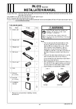
1. Accessory parts
* This part is not used when installing models
367/287/227.
Note:
• This manual provides the illustrations of the
accessory parts and machine that may be
slightly different in shape from yours. In that
case, instead of the illustrations, use the
appearance of your machine to follow the
installation procedure. This does not cause any
significant change or problem with the proce-
dure.
• If none of the later steps instruct you to use the
parts including screw and cover that you
removed following the instructions described in
this manual, discard them.
• After installing the Punch Kit PK-519 to the Fin-
isher FS-533, check again that the punch unit is
securely locked into the finisher before install-
ing, removing, or carrying the finisher.
No.
Name
Shape
Q’ty
1. Punch unit
1
2. Stopper arm
1
3. Stopper pin
1
4. Rail cover
1
5. Front cover
*
1
6. Seal
3
7. Screw A
(3 x 6 mm)
2
8. Screw B
(3 x 6 mm)
1
9. Installation
manual
1
set
Keep this bag away from babies and
children. Do not use in cribs, beds,
carriages, or playpens.
The thin film may cling to nose and
mouth and prevent breathing. This bag is
not a toy.
< OK >
< NG >
Locked
Unlocked


