background image

ASUS

ZD553KL


Service


Manual

2017-06-08

ZD553KL

-1-

              ZD553KL
            

L3-L4)

Customer Service Manual


Version : v1.0

Summary of Contents for L3-L4

Page 1: ...ASUS ZD553KL Service Manual 2017 06 08 ZD553KL 1 ZD553KL L3 L4 Customer Service Manual Version v1 0 ...

Page 2: ...t Analysis 1 Boot class fault 12 2 Display class fault 16 3 Sound class fault 19 4 Touch screen fault 29 5 Charging fault 28 6 Motor fault 33 7 SIM UIM T Card identification fault 35 8 Camera type failure 39 9 GPS WIFI BT failure 44 10 FM demodulation circuit failure 47 11 Front and rear flash bad 50 12 Light distance sensor failure 52 13 Gyrosensorfault 54 RF class failure Refer to RF bad analysi...

Page 3: ... with previous single Camera 13 0M FF Main Camera F2 2 16M AF OV SAMSUNG Compatible with 13 0M AF 2 Flash LED Front and rear single flash 3 SIM Dual SIM Dual Standby Nano SIM slot 2 support DSDS 4G 3G Sim1 Sim2 support LTE interchangeable SIM Tray Keep Nano SIM 2 micro SD 3 election 3 4 Sensor 1 Accelerator 2 E Compass 3 Proximity 4 Ambient light sensor 5 Gyroscope6 Hall sensor 5 Fingerprint recog...

Page 4: ...ASUS L3 Service Manual 2017 06 08 ZD553KL 4 二 Mobile phone structure diagram 1 ZD553KL Motherboard PCBA diagram ...

Page 5: ...L3 Service Manual 2017 06 08 ZD553KL 5 ASUS ...

Page 6: ...L3 Service Manual 2017 06 08 ZD553KL 6 ASUS ...

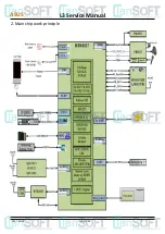
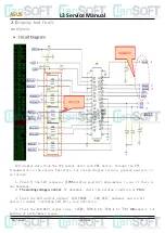
Page 7: ...ASUS 2017 06 08 ZD553KL 7 2 Main chip work principle L3 Service Manual ...

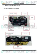
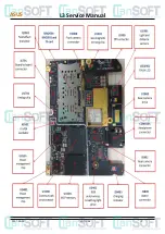
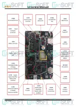
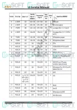
Page 8: ...ASUS L3 Service Manual 2017 06 08 ZD553KL 8 ...

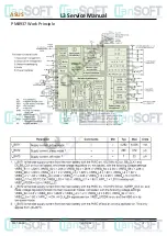
Page 9: ...ASUS L3 Service Manual 2017 06 08 ZD553KL 9 PM8937 Work Principle ...

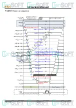
Page 10: ...ASUS L3 Service Manual 2017 06 08 ZD553KL 10 PM8937 Power on sequence ...

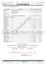
Page 11: ...ASUS L3 Service Manual 2017 06 08 ZD553KL 11 Power on timing specifications ...

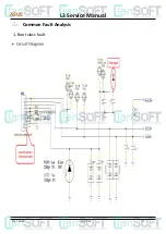
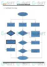
Page 12: ...ASUS L3 Service Manual 2017 06 08 ZD553KL 12 三 Common Fault Analysis 1 Boot class fault ...

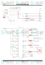
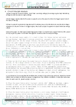
Page 13: ...ASUS L3 Service Manual 2017 06 08 ZD553KL 13 ...

Page 14: ...ally cut off the output current so that the phone will not have greater damage adjust the power supply voltage of 4 0 V the output can supply current of 2 0A is appropriate Through the fake battery to the PCBA power test 1 Power on the first press the power button to observe the shutdown leakage current if the leakage current is very large focus on checking with VBAT connected devices with a multi...

Page 15: ...L3 Service Manual 2017 06 08 ZD553KL 15 ASUS check if the 19 2M crystal is work change the 19 2M crystal or solder it again ...

Page 16: ...lysis is as follows 1 Check if the LCD connector J1705 welding good dirt phenomenon to see if there is any breakage 2 The working voltage is normal If abnormal check the welding condition of PMU 3 Check the LCD control signals LCM_FMARK LCM_RSTN pathways and circuit device is normal including LCD_ID is less effective 4 Check the LCD MIPI signal lines TCN P TDP0 N0 TDP1 N1 EMI Filter device for wel...

Page 17: ...L3 Service Manual 2017 06 08 ZD553KL 17 ASUS ...

Page 18: ...e LCD screen solder joints are good especially the backlight control signal LEDA LEDK two pins 2 Check LCD backlight LEDA 18 v voltage is normal the line device on the feedback signal LEDK normal 3 LCD backlight LEDA abnormal voltage first check U0401 welding problems and peripherals check the enable signal LCM_BL_PWM is normal 4 Start signal LCM_BL_PWM is not normal check whether the output of th...

Page 19: ...L3 Service Manual 2017 06 08 ZD553KL 19 ASUS 3 Sound class fault MIC fault analysis ...

Page 20: ...microphone through the FPC to the motherboard to provide normal send function located at the top of the motherboard MIC1600 for the auxiliary microphone to provide noise reduction function the normal work The microphone provides a bias voltage the microphone starts to pick up and the signal passes through a coupling capacitor into the power supply chip ...

Page 21: ...L3 Service Manual 2017 06 08 ZD553KL 21 ASUS Headphone failure analysis ...

Page 22: ...an not identify the headset focusing on checking the headphone detection signal EAR_DET is normal can identify the headset but the transmission is faulty then check the microphone under the microphone check HP_MIC EAR_DET and U1602 between the normal Headphone MIC circuit related devices are damaged Weld ...

Page 23: ...L3 Service Manual 2017 06 08 ZD553KL 23 ASUS Receiver Failure Analysis ...

Page 24: ...e receiver itself is good replace the test the receiver using shrapnel crimping confirm and PCBA crimping good contact points should be clean no dirt etc Finally check the voice signal AU_HSP AU_HSN and power chip access Welding or replacing the power supply chip ...

Page 25: ...L3 Service Manual 2017 06 08 ZD553KL 25 ASUS SPK Failure Analysis ...

Page 26: ...ASUS L3 Service Manual 2017 06 08 ZD553KL 26 ...

Page 27: ...2 Check whether the horn shrapnel and FPC are in good contact 3 Check that the FPC path is connected 4 Check that the FPC and the motherboard connectors are crimping properly 5 Check R1607 and 1608 resistance is normal 6 Check whether the U1500 chip Weld and finally replace the U1500 chip ...

Page 28: ...ASUS L3 Service Manual 2017 06 08 ZD553KL 28 4 Touch screen failure ...

Page 29: ...tor for the motherboard J1702 including power reset interrupt I2C clock I2C data and GND signal TP signal on the parallel TVS tube to prevent static electricity Power supply from the power supply chip U1902 the remaining signal through the 0 ohm resistor directly connected to the main chip U1500 ...

Page 30: ...ASUS L3 Service Manual 2017 06 08 ZD553KL 30 5 Charging Fault Analysis ...

Page 31: ...ASUS L3 Service Manual 2017 06 08 ZD553KL 31 ...

Page 32: ...onnected to the phone the phone no response the other is the phone although there is a charge display but can not charge the battery For non charging fault machine please check the I O interface to see if there is obvious damage Charger connected to the phone the phone has a charge indication but can not charge the battery ...

Page 33: ...L3 Service Manual 2017 06 08 ZD553KL 33 6 Motor Fault Analysis ASUS ...

Page 34: ...ASUS L3 Service Manual 2017 06 08 ZD553KL 34 The machine uses flat motor the use of FPC connector connection operating voltage of about 2 8V current 60mA or so directly from the power chip motor control ...

Page 35: ...L3 Service Manual 2017 06 08 ZD553KL 35 7 SIM UIM T Card Fault Analysis ASUS ...

Page 36: ... card can check the relevant circuit Fault not card analysis process is as follows 1 The first SIM booth of welding and examine whether the pin height consistent 2 Review the working voltage of SIM card VDDSIM is normal 3 Check the SIM card control signals SIM_SCLK SIM_DA lines is normal 4 No problem with the above checks the CPU is replaced ...

Page 37: ... card VDD SD normal and abnormal check line device on the welding is normal then change PMU 2 Review the T card control signals SDC2_SDCARD_DAT2 3 SDC2_SDCARD_CMD and SDC2_SDCARD_CLK on a line welding device is normal 3 No problem with the above checks the CPU is replaced ASUS ...

Page 38: ...ASUS L3 Service Manual 2017 06 08 ZD553KL 38 ...

Page 39: ...ASUS L3 Service Manual 2017 06 08 ZD553KL 39 8 Camera type failure ...

Page 40: ...ASUS L3 Service Manual 2017 06 08 ZD553KL 40 ...

Page 41: ...ASUS L3 Service Manual 2017 06 08 ZD553KL 41 ...

Page 42: ...ASUS L3 Service Manual 2017 06 08 ZD553KL 42 ...

Page 43: ...de angle 120 optical Compatible with previous single Camera 13 0M FF Main Camera F2 2 16M AF OV SAMSUNG Compatible with 13 0 M AF are through the MIPI interface through the EMI filter and BB chip connection using 1 2V_LDO 1 8V_LDO 2 8V_LDO 3V_LDO four power supply The master chip U1500 is controlled by the U1800 ...

Page 44: ...L3 Service Manual 2017 06 08 ZD553KL 44 9 WIFI BT GPS fault analysis ASUS ...

Page 45: ...L3 Service Manual 2017 06 08 ZD553KL 45 ASUS ...

Page 46: ...enerated 2 4 G and 5 G use the spectrum analyzer to check whether the normal RF channel 3 Check WIFI BT RF circuit operating voltage is normal if abnormal check PMU 4 Check the CPU and circuit between the WIFI TX RF signal RX CTRL you can change the continuous U2900 and U1500 to confirm whether the welding is good 5 Check GPS RF signals between the CPU and RX CTRL can change of successive U2900 an...

Page 47: ...ASUS L3 Service Manual 2017 06 08 ZD553KL 47 10 FM demodulation circuit failure ...

Page 48: ...ASUS L3 Service Manual 2017 06 08 ZD553KL 48 ...

Page 49: ...ood contact if there is a headphone symbol display whether the wiring device is good for the welding line 2 Check the FM module operating voltage is normal such as abnormal replacement PMU 3 Check whether XO_IN is normal 3 Check that the U2900 output is normal with the CPU FM signal demodulation circuit FM_DATA and FM_SSBI ...

Page 50: ... 11 Front and rear flash bad Front flash for LED1902 After the flash is U1901 you can enter the strong flash mode by pulling the TORCH and VFLASH high at the same time Power supply for the VPH_PWR the output voltage to drive LED1901 LED1902 light ...

Page 51: ...ASUS L3 Service Manual 2017 06 08 ZD553KL 51 ...

Page 52: ...L3 Service Manual 2017 06 08 ZD553KL 52 12 Light distance sensor failure ASUS ...

Page 53: ...L3 Service Manual 2017 06 08 ZD553KL 53 Light sensor on the motherboard U1901 the signal includes VREG_L10_2P8 power Supply I2C1 clock I2C1 data INT and GND ASUS ...

Page 54: ...ASUS L3 Service Manual 2017 06 08 ZD553KL 54 13 Gyro sensor failure ...

Page 55: ...t the direction of rotation of a rotating object in the direction of the impact from the external force it will not change Use it to keep the direction And then read the direction indicated by the axis in a variety of ways and automatically pass the data signal to the control system ...

Reviews: