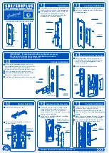
Asus DL101, User Manual
The Asus DL101 User Manual is a comprehensive guide that provides step-by-step instructions for hassle-free setup and optimal usage of the Asus DL101 device. Download this manual for free from our website and unlock the full potential of your Asus DL101 with ease and convenience.
Share
Download


Reviews:
No comments
Related manuals for DL101
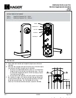
4500 Series
Brand: hager Pages: 3
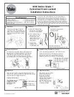
5400 Series
Brand: Yale Pages: 2
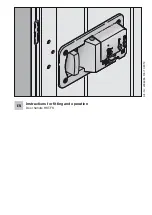
HST-FS
Brand: 4Ddoors Pages: 11
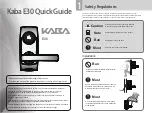
E30
Brand: Kaba Pages: 4
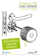
125
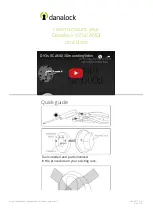
Brand: danalock Pages: 4
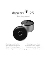
125
Brand: danalock Pages: 32

L701
Brand: Waferlock Pages: 3
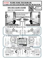
SHS-3321
Brand: Samsung Pages: 2
shs-h705
Brand: Samsung Pages: 2

TOUCH
Brand: Wattle Pages: 40
V3 SCANDI
Brand: danalock Pages: 8

V3 SCANDI
Brand: danalock Pages: 24
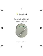
V3 EURO
Brand: danalock Pages: 32
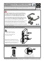
D-110
Brand: Eco Pages: 4
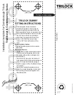
Contemporary Series
Brand: Gainsborough Pages: 2
SD8
Brand: Gainsborough Pages: 2
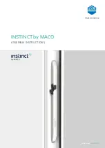
INSTINCT
Brand: Maco Pages: 35
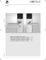
DT 700
Brand: Hafele Pages: 16


