background image


  Last Updated: September 22, 2021


SRG-ADIO 


IoT  Gateway  System 


User’s  Manual 

1

st

  Ed

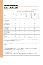
Summary of Contents for AAEON SRG-ADIO

Page 1: ...Last Updated September 22 2021 SRG ADIO IoT Gateway System User s Manual 1st Ed ...

Page 2: ...in this manual is intended to be accurate and reliable However the original manufacturer assumes no responsibility for its use or for any infringements upon the rights of third parties that may result from its use The material in this document is for product information only and is subject to change without notice While reasonable efforts have been made in the preparation of this document to assur...

Page 3: ...Cortex and Cortex A8 are registered trademarks of Arm Limited or its subsidiaries ITE is a trademark of Integrated Technology Express Inc IBM and VGA are trademarks of International Business Machines Corporation Ubuntu is a registered trademark of Canonical All other product names or trademarks are properties of their respective owners No ownership is implied or assumed for products names or trade...

Page 4: ...O Packing List Before setting up your product please make sure the following items have been shipped Item Quantity SRG ADIO 1 If any of these items are missing or damaged please contact your distributor or sales representative immediately ...

Page 5: ... descriptions and explanations on the product s hardware and software features if any its specifications dimensions jumper connector settings definitions and driver installation instructions if any to facilitate users in setting up their product Users may refer to the product page at AAEON com for the latest version of this document ...

Page 6: ... system s hardware 6 No connections should be made when the system is powered as a sudden rush of power may damage sensitive electronic components 7 If the device is not to be used for a long time disconnect it from the power supply to avoid damage by transient over voltage 8 Always disconnect this device from any AC supply before cleaning 9 While cleaning use a damp cloth instead of liquid or spr...

Page 7: ...rs 18 If any of the following situations arises please the contact our service personnel i Damaged power cord or plug ii Liquid intrusion to the device iii Exposure to moisture iv Device is not working as expected or in a manner as described in this manual v The device is dropped or damaged vi Any obvious signs of damage displayed on the device 19 DO NOT LEAVE THIS DEVICE IN AN UNCONTROLLED ENVIRO...

Page 8: ...losion if the battery is incorrectly replaced Replace only with the same or equivalent type recommended by the manufacturer Dispose of used batteries according to the manufacturer s instructions and your local government s recycling or disposal directives Attention Il y a un risque d explosion si la batterie est remplacée de façon incorrecte Ne la remplacer qu avec le même modèle ou équivalent rec...

Page 9: ... 铅 Pb 汞 Hg 镉 Cd 六价铬 Cr VI 多溴联苯 PBB 多溴二苯 醚 PBDE 印刷电路板 及其电子组件 外部信号 连接器及线材 外壳 中央处理器 与内存 硬盘 液晶模块 光驱 触控模块 电源 电池 本表格依据 SJ T 11364 的规定编制 表示该有毒有害物质在该部件所有均质材料中的含量均在 GB T 26572标准规定的限量要求以下 表示该有害物质的某一均质材料超出了GB T 26572的限量要求 然而该 部件 仍符合欧盟指令2011 65 EU 的规范 备注 一 此产品所标示之环保使用期限 系指在一般正常使用状况下 二 上述部件物质中央处理器 内存 硬盘 光驱 电源为选购品 三 上述部件物质液晶模块 触控模块仅一体机产品适用 ...

Page 10: ...PSU X O O O O O Battery X O O O O O This form is prepared in compliance with the provisions of SJ T 11364 O The level of toxic or hazardous materials present in this component and its parts is below the limit specified by GB T 26572 X The level of toxic of hazardous materials present in the component exceed the limits specified by GB T 26572 but is still in compliance with EU Directive 2011 65 EU ...

Page 11: ...m 14 3 2 User Account Management 17 3 3 Network Settings 18 3 3 1 Check IP Settings 18 3 3 2 Set Static IP 19 3 3 3 Set Dynamic IP 20 3 4 Cellular Network Settings 21 3 4 1 Check Cellular Module Status 21 3 4 2 Dial Up Cellular Module 22 3 5 Wi Fi and Bluetooth Network Settings 23 3 5 1 Scan for Wi Fi Access Points 23 3 5 2 Connect to Wi Fi Access Point 23 3 5 3 Disconnect from Wi Fi Access Point ...

Page 12: ... 7 I O Management 30 3 7 1 Control GPIO LEDs 30 3 7 2 RS 485 2 wire Pin Definition SRG 3352C 31 3 7 3 RS 232 422 485 CAN Bus Pin Definitions SRG ACAN 32 3 7 3 1 Manage RS 232 422 485 Mode 34 3 7 3 2 CAN Bus Read Write 35 3 7 4 ADC Digital I O Pin Definitions SRG ADIO 36 3 7 4 1 Wiring Diagram 37 3 7 4 2 Manage Digital I O 39 3 7 4 3 Manage Analog Input 4CH Signal End 40 3 7 4 4 Manage Analog Input...

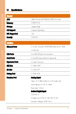
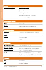
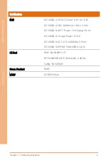
Page 13: ...IOT Gateway System SRG ADIO Chapter 1 Chapter 1 Product Specifications ...

Page 14: ...rts 2 x Auto sensing 10 100 1000 Mbps ports RJ45 connector USB Ports 2 x USB2 0 Type A Connector Serial Ports 2 x RS485 Terminal Block optional Expansion Ports 1 x Mini PCIe Slot SIM Slot 1 x Micro SIM SD Slot 1 x microSD Debug Port 1 x Mini USB Function Port Analog Input Type 2 CH differential or 4 CH single end Input Range 0 15V 0 20mA Resolution 16 bit Isolated Digital Input Channel 4 Voltage L...

Page 15: ...h Bluetooth 4 2 and Bluetooth low energy Physical Characteristics Dimensions 4 3 x 4 33 x 1 54 109mm x 110mm x 39mm Weight 430 g Mounting DIN rail mounting Wall Mount Environmental Operating Temperature 32 F 140 F 0 C 60 C Operating Humidity 10 95 relative humidity non condensing Storage Temperature 40 F 176 F 40 C 80 C Vibration 2 Grms at IEC 60068 2 64 random wave 5 500 Hz 1 hour per axis withou...

Page 16: ... Air 8 kV IEC 61000 4 3 RS 80 MHz to 1 GHz 3 V m IEC 61000 4 4 EFT Power 1 kV Signal 0 5 kV IEC 61000 4 5 Surge Power 0 5 kV IEC 61000 4 6 CS 0 15 to 80MHz 3 Vrms IEC 61000 4 8 PFMF 50Hz 60Hz 1 A m CE Red EMC EN301489 1 17 RF EN300328 Wi Fi Bluetooth 2 4GHz Safety EN 62368 1 Green Product RoHS MTBF 855 890 Hours ...

Page 17: ...IOT Gateway System SRG ADIO Chapter 2 Chapter 2 Hardware Information ...

Page 18: ...Chapter 2 Hardware Information 6 IoT Gateway System SRG ADIO 2 1 Dimensions ...

Page 19: ... via SSH by debug port Micro USB port 4 RS 485 Terminal Resistor Used when there are long distances between the gateway and RS 485 device 5 Micro SIM Slot Insert micro SIM card into the slot when using LTE module installed in Mini Card slot 6 microSD Slot Increase storage capacity by inserting a microSD card 7 DC Power Jack Gateway supports DC 9 30V input 8 USB2 0 Port USB2 0 type A connector supp...

Page 20: ...een 10 100Mbps Orange 1000Mbps 10 LED LED can be controlled or defined by GPIO settings The control command for LED 1 See Chapter 3 for more information turn on echo 1 sys class leds srt3352 led1 brightness turn off echo 0 sys class leds srt3352 led1 brightness 11 Function Port The function port supports ADC Digital I O functions Pin Definition Pin Definition Upper Row Lower Row 1 DO_VCC 10 AI_GND...

Page 21: ...Chapter 2 Hardware Information 9 IoT Gateway System SRG ADIO 12 Mini Card Slot The Mini PCIe slot can support LTE modules USB signal ...

Page 22: ...onnecting to wireless networks such as 4G This section details how to install a SIM Card and 4G LTE module on the mini card slot 2 3 1 Mini Card Installation Step 1 Remove the top cover by removing the 6 screws Step 2 Open the antenna hole by removing the cover on the hole located on the left side Step 3 Install the RF coaxial cable in the antenna hole ...

Page 23: ...stem SRG ADIO Step 4 Remove the bottom cover and install the 4G LTE module in the Mini Card slot and connect the coaxial cable to the 4G LTE module Step 5 Place the bottom cover and secure with screws Step 6 Place the top cover and secure with screws ...

Page 24: ...ation 12 IoT Gateway System SRG ADIO 2 3 2 SIM Card Installation To install a SIM Card Micro SIM simply insert the SIM Card into the slot on the side of the system as shown Take care to make sure the card is oriented correctly ...

Page 25: ...IOT Gateway System SRG ADIO Chapter 3 Chapter 3 Gateway Setup and Configuration ...

Page 26: ...eir PC to recognize the system The following instructions detail how to set up your PC to connect to the SRG ADIO system by installing the CDC Serial Driver The CDC Serial Driver can be downloaded from the SRG ADIO product page on AAEON com Step 1 Download the PuTTY software Step 2 Connect the host PC to the gateway with a USB cable to the Micro USB port Step 3 Open Device Manager and locate Multi...

Page 27: ...5 IoT Gateway System SRG ADIO Step 4 Open PuTTY and use the following settings to connect to the system Serial Port Settings Baud Rate 115200 bps Parity None Data bits 8 Stop bits 1 Flow Control None Click Open to connect with the gateway system ...

Page 28: ...Gateway Setup and Configuration 16 IoT Gateway System SRG ADIO Step 5 You will see the login prompt once the host PC successfully connects to the gateway Default login information is Username aaeon Password aaeon ...

Page 29: ...ils how to manage user accounts on the system Add User Account Command Line sudo useradd m G sudo s bin bash USERACCOUNT USERACCOUNT Account name you want to add Return test3 is the account name in this example Delete User Account Command Line sudo userdel USERACCOUNT USERACCOUNT Account name you want to delete Result ...

Page 30: ...e IP setting by entering the following command into Terminal Command Line nmcli con show NETWORKPROFILE NETWORKPROFILE refers to one of the system s network connections as follows NETWORKPROFILE Port Hardware Ethernet0 LAN1 Ethernet1 LAN2 Modem 4G LTE module For example to pull up the IP settings for LAN1 us the following command nmcli con show Ethernet0 You should see the following results ...

Page 31: ...rn the following Ethernet0 used in this example Step 2 Edit the IP Address with the following commands nmcli goto ipv4 nmcli set address IPADDRESS 24 IPADDRESS is the address you wish to use This example uses 192 168 3 127 nmcli save nmcli quit You have now exited the edit mode sudo ifconfig PORT down sudo ifconfig PORT up PORT variables are eth0 for Ethernet0 or eth1 for Ethernet1 this example us...

Page 32: ...owing command nmcli con edit NETWORKPROFILE See table in 3 3 1 for NETWORKPROFILE values Command should return the following Ethernet0 used in this example Step 2 Edit the IP address with the following commands nmcli goto ipv4 nmcli remove address nmcli save nmcli quit You have now exited edit mode The following should be returned ...

Page 33: ...DIO 3 4 Cellular Network Settings This section details how to check and manage the cellular network settings 3 4 1 Check Cellular Module Status Step 1 To check the status of the cellular module enter the following command mmcli m 0 The system should output the following ...

Page 34: ...atus if the module is ready to use If there is an issue the state will show failed along with a failed reason such as sim missing Step 2 Enable the cellular module with the following command mmcli m 0 e System will return the following if successful Step 3 Dial up the cellular module with the following command nmcli con up id Modem System will return the following Step 4 You can check the cellular...

Page 35: ...access points enter the following command nmcli dev wifi The system will return a list of Wi Fi networks with their name signal strength and security type 3 5 2 Connect to Wi Fi Access Point To connect to a Wi Fi network enter the following command nmcli dev wifi connect SSID password PASSWORD SSID is the name of the network you want to connect to PASSWORD is the network password for the chosen SS...

Page 36: ...nmcli con down id SSID SSID is the name of the network you want to disconnect from The system will return the following if successful 3 5 4 Check Wi Fi Connection Status To check the status of a Wi Fi connection enter the following command nmcli dev If connected the system will return a connected status for wlan0 If disconnected the system will return disconnected status for wlan0 ...

Page 37: ...ou must first enter the Bluetooth Control Panel with the following command sudo bluetoothctl The system will return the following 3 5 6 Scan for Bluetooth Device To scan for a Bluetooth Device enter the following commands power on This command turns on the Bluetooth module scan on The system will return a list of devices and their MAC addresses ...

Page 38: ...while in the control panel pair MAC_ID MAC_ID is the MAC address of the device you wish to connect to This example is connecting to device E8 6F 38 83 CF 10 3 5 8 Check Pared Bluetooth Devices To check which Bluetooth devices are paired with the system use the command paired devices The system will return a list of connected devices and their MAC addresses ...

Page 39: ...tem Management This section details how to check the OS version storage device status shutdown the system and set the date and time 3 6 1 Check OS Version To check which OS version the system is running enter the command cat etc os release The system will return the OS information ...

Page 40: ...em storage enter the following command df h The system will return a list of storage devices capacity and usage 3 6 3 Shut Down the System To force the system to shut down use following command Note you may need to enter the user password sudo shutdown now On successful shutdown terminal will return Error reading from serial device ...

Page 41: ...d time by issuing the following command timedatectl The system will return the current system clock settings Step 2 Change the date and time by issuing the following command date MMDDhhmmYYYY Command uses the following formatting MM Month DD Day hh Hour in 24 hour clock mm Minute YYYY Year The system will return the following ...

Page 42: ...nectors 3 7 1 Control GPIO LEDs To control the GPIO manually issue the following commands this example uses led1 GPIO On echo 1 sys class leds srt3352 led1 brightness GPIO Off echo 0 sys class leds srt3352 led1 brightness Use the following table to reference each LED label for the command Number Label Picture Number Label Picture 1 Red led1 3 Yellow led3 2 Green Led2 4 Orange led4 ...

Page 43: ...nd Configuration 31 IoT Gateway System SRG ADIO 3 7 2 RS 485 2 wire Pin Definition SRG 3352C Note This feature is only on the SRG 3352C Label System Reference COM1 dev ttyS4 COM2 dev ttyS5 Pin Signal 1 DATA 2 DATA 3 4 5 6 7 8 9 ...

Page 44: ... of SRG ACAN which you can verify by checking which interface ports your system has SRG ACAN A10 0001 has one COM port and one CAN Bus Port SRG ACAN A10 0002 has two COM ports only SRG ACAN A10 0001 COM CAN Bus Label System Reference COM1 dev ttyMU0 CAN Bus N A Pin COM1 Signal CAN Signal 1 DCD GND 2 RXD AI_2 3 TXD AI_4 4 DTR CAN1_H 5 GND CAN0_H 6 DSR AI_1 7 RTS AI_3 8 CTS CAN1_L 9 RI CAN0_L ...

Page 45: ...tion 33 IoT Gateway System SRG ADIO SRG ACAN A10 0002 2 x COM Ports Label System Reference COM1 dev ttyMU0 COM2 dev ttyMU1 Pin COM1 Signal COM2 Signal 1 DCD DCD 2 RXD RXD 3 TXD TXD 4 DTR DTR 5 GND GND 6 DSR DSR 7 RTS RTS 8 CTS CTS 9 RI RI ...

Page 46: ...O System Name Port Label 0 dev ttyMU0 COM1 1 dev ttyMU1 COM2 Example will return mode for COM1 sudo uartmode p 0 The command will output a single number Refer to the table below for each mode PORTMODE COM Mode 0 RS 232 1 RS 485 2 wire 2 RS 422 RS 485 4 wire Switch Mode by entering the following command sudo uartmode p PORTNO m PORTMODE Refer to the tables above for PORTNO and PORTMODE The system w...

Page 47: ...o Read or Write use the following commands Initialize CAN Bus sudo srg52 initcan CANNO BAUDRATE CAN Bus Read sudo can_read CANNO CAN Bus Write sudo can_write CANNO CANNO variable is either can0 or can1 CANNO System Name can0 can0 can1 can1 BAUDRATE should be the specific baud rate for the current CAN bus Example and results ...

Page 48: ... 4 ADC Digital I O Pin Definitions SRG ADIO Note This feature is only on the SRG ADIO Pin Definition Pin Definition Upper Row Lower Row 1 DO_VCC 10 AI_GND 2 DO_1 11 AI_4 3 DO_VCC 12 DI_3 4 NC 13 AI_3 5 DO_2 14 DI_2 6 NC 15 AI_2 7 DO_3 16 DI_1 8 DI_4 17 AI_1 9 DO_4 18 DI_Common ...

Page 49: ...Chapter 3 Gateway Setup and Configuration 37 IoT Gateway System SRG ADIO 3 7 4 1 Wiring Diagram Analog Input Digital Input ...

Page 50: ...Chapter 3 Gateway Setup and Configuration 38 IoT Gateway System SRG ADIO Digital Output ...

Page 51: ...Use the following command to set digital output state to ON or OFF setdo CHANNEL STATE CHANNEL 0 1 2 or 3 STATE set to 1 for ON or 0 for OFF Example Get Digital Input Status Use the following command to check the status of digital input getdi CHANNEL CHANNEL 0 1 2 or 3 The system will return a value of 1 for ON and 0 for OFF ...

Page 52: ...nel use the following numerical inputs 0 Voltage 1 Current 1 Disable no value will be returned For example The following command will return voltage values for all four channels rd_exadc a 0 0 0 0 The system will output information based on the inputs you used as follows To view status for a specific channel use the following command rd_exadc c CHANNEL M MODE CHANNEL is the channel you wish to che...

Page 53: ...oT Gateway System SRG ADIO 3 7 4 4 Manage Analog Input 2CH Differential To check Group status use the following command rd_exadc g GROUP m 0 GROUP enter 0 for group 0 ch0 and ch1 enter 1 for group 1 ch2 and ch3 The system will return the following ...

Reviews: