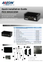


Quick Installation Guide
PICO-WHU4-SEMI
This document will guide
you through the basic
installation process for your
new PICO-WHU4-SEMI.
PICO-WHU4-SEMI
Item
Description
Remark/PN
1
PICO-WHU4 Board (with CMOS battery)
2
System Case
3
SATA Cable
170X000101
4
SATA Power Cable
1702150130
5
USB 2.0 Ports/Cable
170010010D
6
USB Port mounting bracket
M001720000
7
Power Button
170010020T
8
4x Screws.M3.Nickel
S1D5106010
10x screws.M3.Black
S1D3004031
2x Zip Ties (included, optional use)
1992666607
2x Zip Tie anchors (included, optional use)
199266660B
9
Dual COM Port/Cable (optional)
1701200102
10
PICO-WHU4-SEMI VESA bracket kit (optional)
PICO-WHU4-SEMI-VESA1
11
PICO-WHU4-SEMI Wallmount bracket kit (optional)
PICO-WHU4-SEMI-WMT1
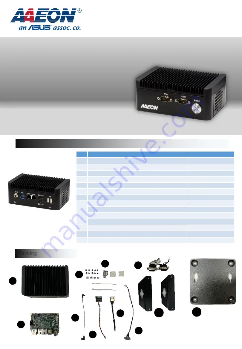
Packing
2
3
4
1
5
Note:
Zip ties and anchors are included for cable management but are not required
to complete the system assembly.
6
7
8
9
User Supplied Components:
2.5” SATA Drive (SSD)
144 pin SO-DIMM RAM module up to 32 GB
10
11