background image

P610

Programming Panel

Operating Instructions

A91M.12-271893.22-0891EN

Translation of the German Description

A91M.12-271689

Summary of Contents for P610

Page 1: ...P610 Programming Panel Operating Instructions A91M 12 271893 22 0891EN Translation of the German Description A91M 12 271689 ...

Page 2: ......

Page 3: ...essary to install the EMS driver that is included on the operating system diskette EMS Driver Installation To install the driver it has to be entered into the file CONFIG SYS Please execu te the following steps Schritt 1 Use an ASCII editor of your device Schritt 2 Open the file CONFIG SYS in your system directory Schritt 3 Add the following line in this file DEVICE drive directory EMM386 SYS size...

Page 4: ......

Page 5: ...ation concerning the sys tem see addresses Data Illustrations Alterations Data and illustration are not binding We reserve the right to alter our products in line with our policy of continuous product development If you have any sugges tions for improvements or amendments or have found errors in this publication please notify us by using the form on the last page of this publication Addresses The ...

Page 6: ... are not authorized to translate this document into any other language Trademarks All terms used in this user manual to denote AEG products are trademarks of the AEG Aktiengesellschaft IBM IBM PC IBM XT and IBM AT are registered trademarks of International Business Machines Corporation Microsoft and MS DOS are registered trademarks of Microsoft Corporation TOSHIBA is a registered trademark of TOSH...

Page 7: ...xclusively for experts special training re quired Skipping this information does not interfere with understand ing the publication and does not restrict standard application of the product Path This symbol identifies the use of paths in software menus Figures are given in the spelling corresponding to international practice and ap proved by SI Système International d Unités I e a space between the...

Page 8: ...facturers Arrangement of This Guide Chapter 1 describes the range of performance features of the P610 Chapter 2 describes the keyboard and the handling of diskettes Chapter 3 describes requirements for programming with P610 Chapter 4 describes errors and their correction Chapter 5 contains specifications of the P610 Related Documents Documents that are related to the special system are necessary ...

Page 9: ...rmation given in this manual apply only to performance features and func tions if you use the attached MS DOS version 3 3 Programming of A250 AKF125 is possible using the P610 programming panel from device index 03 5 Mbyte RAM ...

Page 10: ...Use of the Diskettes 10 2 2 1 Insert Diskette 11 2 2 2 Remove Diskette 11 2 3 MS DOS Instructions 12 Chapter 3 Programming Requirements 13 3 1 Power Supply 14 3 2 Initial Start up 14 3 3 Installation of the Software 14 3 4 Peripheral Connection Field 15 3 5 Connection to the Programmable Controller 16 3 5 1 Cable Connection 17 3 5 2 Start up Conditions at the Programmable Controller 17 3 6 Connect...

Page 11: ...tar 200 PC 23 3 10 1 1 Communication Module 23 3 10 1 2 External Monitors 24 3 10 2 Viewstar 200 XA 25 3 11 Connection to the FD 300 Diskette Drive 26 3 12 Installation of PC Modules 27 Chapter 4 Errors and their Correction 29 Chapter 5 Specifications 33 Power Supply 34 Ports 34 Processor 34 Memory 35 Screen 35 Keyboard 35 Clock Calendar 36 Environmental Characteristics 36 Physical Characteristics...

Page 12: ...d 16 Figure 10 Printers which can be Connected 18 Figure 11 EPROM Programming Stations which can be Connected 20 Figure 12 Communication Module for Modicon 984 21 Figure 13 Connection to Viewstar B500 22 Figure 14 Communication Module for Viewstar 200 PC 23 Figure 15 External Monitors for Viewstar 200 PC 24 Figure 16 Connection to Viewstar 200 XA 25 Figure 17 Connection to the FD 300 26 Tables Tab...

Page 13: ...22 Table of Contents xii ...

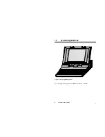
Page 14: ...22 General Information 1 Chapter 1 General Information Use and Applications Features ...

Page 15: ...22 General Information 2 1 1 Use and Applications Figure 1 P610 Programming Panel The P610 programming panel is an IBM AT compatible computer ...

Page 16: ...oring devices as Modbus plus node at Modicon 984 as an operating and monitoring device for process display with the Viewstar 200 PC as external memory for the Viewstar B500 color video system to archive the programs on 31 2 diskette 51 4 diskette in connection with the FD 300 diskette drive EPROM in connection with the EPS 2000 or EPS 386 as a personal computer PC with the MS DOS operating system ...

Page 17: ...rive 31 2 1 44 Mbyte 720 kbyte Plasma screen with 640 x 480 points resolution VGA and 16 gray levels Socket for external AT keyboard British keyboard with German key caps RGB port VGA EGA and VGA supported for analog screens 2 x RS 232 C port Centronics port 1 Full format expansion slot 16 Bit 1 Half format expansion slot for 8 Bit TOSHIBA expansion card or 8 Bit IBM expansion card Automatic power...

Page 18: ...21 Operation 5 Chapter 2 Operation Operating and Display Elements Use of the Diskettes MS DOS Instructions ...

Page 19: ...tion 6 2 1 Operating and Display Elements Operator Keyboard 3 1 2 Diskette Drive Socket for Ext Keyboard Reset Key PRT B A Switch Display Elements Brightness control Figure 2 P610 Operating and Display Elements ...

Page 20: ... no external diskette drive is used or if a printer is connected A External diskette drive has the code A B External diskette drive has the code B These codes must also be set at the external diskette drive 2 1 2 Display Elements Power Disk in Use HDD FDD Caps Lock Num Lock Scroll Lock Figure 4 Display Elements Power is lit Power Supply exists is not lit Power supply missing Disk in Use HDD is lit...

Page 21: ...k is lit Number block used for number input is not lit Number block used for cursor control Scroll Lock is lit Roll screen contents in is not lit Roll screen contents out 2 1 3 Operator Keyboard E R T Z U I O P A S D F G H J K L Y X C V B N M 1 F1 F2 F3 F4 F5 F6 F7 F8 F9 F10 F11 F12 W 2 3 4 5 6 7 8 9 0 ß Q Ü Ö Ä _ 4 2 8 6 7 9 1 3 0 5 Escape key Control key PrtSc key Alt key Shift key Shift key Con...

Page 22: ...or External Keyboard An external IBM compatible AT keyboard can be connected to this socket The plastic cover of the socket must then be removed before the first use 2 1 6 Reset Key A warm restart is initiated by pressing this key This key is imbedded in order to prevent accidental pressing The reset key can only be actuated with a pointed object e g pencil ...

Page 23: ...oxes Insert diskettes correctly No water on diskettes No heavy objects on diskettes Diskettes tolerate no heat sunshine No erasing on diskettes Don t move the metal slide No forcing diskettes into disk drive Always keep in mind No diskettes near mag netic fields Label diskettes at the right spot 10 to 60 C Figure 6 Use of the 3 1 2 Diskettes ...

Page 24: ...ce If the diskette is inserted incorrectly it is disabled In this case do not try to insert the diskette again Remove the diskette and insert it correctly 2 2 2 Remove Diskette Step 1 Make sure that the LEDs Disk in Use are no longer lit Step 2 Press the floppy disk ejection key The diskette now ejects a little from the drive slit Step 3 Remove the diskette carefully from the drive ...

Page 25: ...ons It is not necessary to learn the MS DOS instructions when using the P610 Files are copied deleted etc automatically via AEG software Those instructions which are needed when the P610 is used as a PC are de scribed in the MS DOS manual ...

Page 26: ...Requirements The preparatory steps necessary to operate the P610 with the programmable controllers are described below Note The specific programming or configuration of the program mable controllers is explained in the corresponding software descrip tion ...

Page 27: ...r should read especially chapters 2 3 and 5 of the manufacturer s user manual and then start operations Note If no external diskette drive is used the PRT B A switch should be set to PRT see chap 2 1 1 3 3 Installation of the Software Instructions for installing the software can be found in the relevant software package Caution Do not start any memory resident or interrupt con trolled PC programs ...

Page 28: ...t Monitor VGA RS 232 C Port COM1 RS 232 C Port COM2 Centronics Port Printer Printer Viewstar B500 Programmable Controller Viewstar B500 EPROM Programming Station Viewstar 200 XA Viewstar 200 XA Ext Diskette Drive PC module slot Figure 8 Connection Field Rear of P610 ...

Page 29: ...22 Programming Requirements 16 3 5 Connection to the Programmable Con troller A010 A020 plus A030 A130 A350 A500 A120 P610 Modicon 984 A250 Figure 9 Programmable Controllers which can be Connected ...

Page 30: ...lus YDL 057 YDL 057 YDL 057 YDL 052 YDL 057 YDL 052 YDL 057 Table 2 Cable Connection from the P610 to the Programmable Controllers Continu ation A500 ALU 984 X8X 984 A B X 25 pole 9 pole YDL 057 YDL 052 W956 012 W958 001 or W907 015 W956 025 or W907 025 3 5 2 Start up Conditions at the Programmable Controller The baud rate of the P610 is automatically adjusted The baud rate may not ex ceed a value...

Page 31: ...ted Printers with Centronics and RS 232 C V 24 ports can be connected to the P610 Note Make sure that the PRT B A switch is in position PRT 3 6 1 Cable Connection 3 6 1 1 Printer with Centronics port The P610 and the printer are connected with the YDL 32 cable The Centronics port is used on the P610 for this purpose see also Figure 8 ...

Page 32: ...M2 is used on the P610 for this purposes see also Figure 8 3 6 2 Start Printout A printout on the printer is offered using a selection menu or a request in various areas of the software A hardcopy of the screen can be obtained by pressing the Shift PrtSc keys simultaneously If a printout is activated the corresponding printer must be connected switched on and set on line ...

Page 33: ...ng Station EPS 2000 EPS 386 P610 Figure 11 EPROM Programming Stations which can be Connected The P610 and the EPROM programming station are connected with the YDL 36 1 cable and the YDL 44 adapter The RS 232 C port COM1 is used on the P610 in this case see also Figure 8 ...

Page 34: ...n to Modbus plus Modicon 984 3 8 1 Communication Module The communication module SA85 000 is necessary for the Modbus plus This is installed in the PC For installation see chapter 3 12 P610 SA 85 000 Figure 12 Communication Module for Modicon 984 ...

Page 35: ...iewstar B500 When connecting the P610 to Viewstar B500 one can select one of the two RS 232 C ports on the P610 Both ports can be used without limitations The P610 and Viewstar B500 are connected with the YDL 25 cable and the YDL 44 adapter The RS 232 C port COM1 or COM2 is used on the P610 see also Figure 8 ...

Page 36: ...PC you either need the communication module BIK 002 or BIK 003 This is installed in the PC For installation details see chapter 3 12 BIK 002 P610 BIK 003 Figure 14 Communication Module for Viewstar 200 PC Details about the bus cable connection to the communications module can be found in the description of the BIK 002 BIK 003 module ...

Page 37: ...0 1 2 External Monitors CMR 121 P610 CMR 122 Figure 15 External Monitors for Viewstar 200 PC To connect the P610 to one of the monitors you have to use the RGB port on the P610 see also Figure 8 and the cable FA 3 attached to monitors ...

Page 38: ...P610 has to be connected to VIP 101 for Viewstar 200 XA Here the cable YDL 105 local range or the cables YDL 057 and YDL 107 remote range is used The RS 232 C port COM1 is used on the P610 see also Figure 8 VIP 101 P610 Figure 16 Connection to Viewstar 200 XA ...

Page 39: ...connected with the provided cable The end of the cable marked System is plugged into the P610 The Centronics port is used on the P610 for this purpose see Figure 8 The following sequence must be observed in order that the FD 300 be correctly addressed Step 1 Switch off P610 Step 2 Connect FD 300 Step 3 Set PRT B A switch to B Step 4 Switch on FD 300 Step 5 Switch on P610 Note The drive code of the...

Page 40: ... PC modules The half format expansion slot can be configured with a TOSHIBA expansion card 8 Bit or with an IBM expansion card 8 Bit The full format expansion slot can be configured with a 16 Bit expansion card Installation of the different PC modules is described in chapter 12 6 of the man ufacturer s manual ...

Page 41: ...22 Programming Preparation 30 ...

Page 42: ...22 Errors and their Correction 31 Chapter 4 Errors and their Correction ...

Page 43: ...ription User software cannot be executed Possible cause Software is incorrectly installed or partially deleted Corrective measure Install software again Error Description No more data input possible Possible cause System failure Corrective measure Warm restart Error Description No warm restart with Ctrl Alt Del possible Possible cause System failure Corrective measure Press the reset key or switch...

Page 44: ...e Corrective measure Check switch settings see chap 2 1 1 Possible cause Centronics port incorrectly configured Corrective measure Reconfigure In the option Printer Port Type in the Setup Menu Bidirectional must be defined see chap 10 2 in the manufacturer s manual For general operational faults the manufacturer s manual also provides assis tance in locating and correcting faults ...

Page 45: ...22 Errors and their Correction 34 ...

Page 46: ...22 Specifications 35 Chapter 5 Specifications Power Supply Ports Processor Memory Keyboard Clock Calendar Environmental Characteristics Physical Characteristics ...

Page 47: ... Port 2 x RS 232 C V 24 port Centronics parallel port Slots 1 Full format expansion slot 16 Bit 1 Half format expansion slot for TOSHIBA expansion card 8 Bit or IBM expansion card 8 Bit Monitor RGB color monitor VGA Keyboard Socket external numerical keyboard Processor Microprocessor Intel 80386SX with 16 MHz 8 MHz ...

Page 48: ...hard disk access time 19 ms Screen Type Plasma screen Resolution 640 x 480 points VGA Gray Levels 16 Pixel Size 0 20 x 0 24 mm W x H Pixel Distance 0 36 x 0 36 mm W x H Screen Size 230 4 x 172 8 mm W x H Contrast 100 1 Screen Plasma screen and external monitor can be operated simultaneously Keyboard Type German English keyboard Number of Keys 92 ...

Page 49: ...to 70 oC Thermic Gradient 20 oC h Relative Humidity Operation 20 to 80 Storage 5 to 90 Height Relative to NN Operation 60 m to 3 000 m Storage 60 m to 12 000 m Shock Operation 5 g Storage 60 g Vibration Operation 0 3 g Storage 1 g Physical Characteristics Size 370 mm x 395 mm x 99 mm W x H x D Weight 7 9 kg Ordering Details P610 Programming Panel E No 424 277 011 ...

Page 50: ...22 Specifications 39 ...

Page 51: ...7 Modicon 984 21 Viewstar 200 PC 23 D Diskette Insert 11 Remove 11 Use 10 Diskette Drive External 26 Display Elements 7 Caps Lock 8 Disk in Use FDD 8 Disk in Use HDD 7 Num Lock 8 Power 7 Scroll Lock 8 E EPROM Programming Station EPS 2000 20 EPS 386 20 EPROM Programming Stations 20 Cable Connection 20 Error Correction 30 External Diskette Drive 26 External Monitor Viewstar 200 PC 24 F Features 4 K ...

Page 52: ...020 plus 16 A030 16 A120 16 A130 16 A250 16 A350 16 A500 16 Cable Connection 17 PRT B A 7 S Specifications Clock Calendar 36 Environmental Characteristics 36 Keyboard 35 Memory 35 Physical Characteristics 36 Ports 34 Power Supply 14 34 Processor 34 Screen 35 Switch PRT B A 7 U Uses 2 V Viewstar 200 PC 23 Communication Module 23 Viewstar 200 XA 25 VIP 101 25 Viewstar B500 22 Cable Connection 22 ...

Reviews: