AEG AS-BBL1-4000, Manual
The AEG AS-BBL1-4000 is a high-quality product that offers outstanding performance. With its user-friendly interface and advanced features, this manual offers comprehensive guidance on operating and maintaining the AEG AS-BBL1-4000. Download the free manual from our website manualshive.com to unlock the full potential of this exceptional product.
Share
Download


Reviews:
No comments
Related manuals for AS-BBL1-4000
Edge
Brand: Garmin Pages: 32
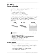
VERSA FX
Brand: NEC Pages: 10
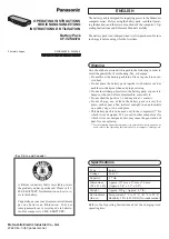
Toughbook CF-29CTKGZKM
Brand: Panasonic Pages: 4
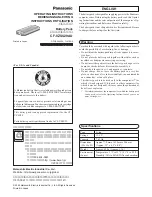
CF-VZSU47U
Brand: Panasonic Pages: 4
EB-U3300
Brand: Samsung Pages: 64
9839
Brand: Gardena Pages: 13
BC 18 V
Brand: Kärcher Pages: 96
E-1 - Digital Camera SLR
Brand: Olympus Pages: 2
PAP 20 B3
Brand: Parkside Pages: 182
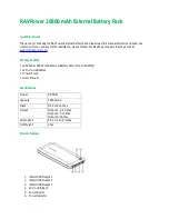
RP-PB41
Brand: Ravpower Pages: 2

evolion
Brand: Saft Pages: 42
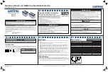
883-0105-12
Brand: Xantrex Pages: 2
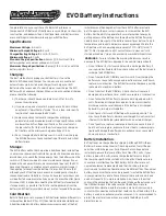
EVO
Brand: Ballistic Pages: 2
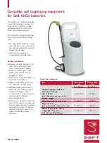
Ni-Cd
Brand: Saft Pages: 4
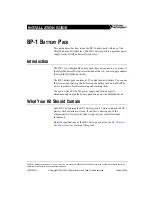
BP-1
Brand: National Instruments Pages: 4

RD-600
Brand: walimex Pages: 12
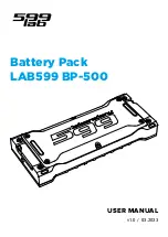
BP-500
Brand: Lab599 Pages: 12
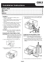
LP441s
Brand: Oki Pages: 4


