background image


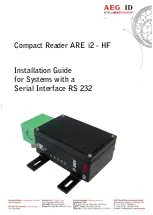
Compact Reader ARE i2 - HF 
 
Installation Guide 
for Systems with a  
Serial Interface RS 232 


Summary of Contents for ARE i2 - HF

Page 1: ...Compact Reader ARE i2 HF Installation Guide for Systems with a Serial Interface RS 232 ...

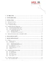
Page 2: ...ing of the external antenna of the AMP 4 AMP 8 13 4 VISUAL SIGNAL LAMPS 14 5 AEG ID INSTRUCTION SET 15 5 1 General 15 5 1 1 Entering instuctions 15 5 1 2 Output format 16 5 1 2 1 Instruction specific output 16 5 1 2 2 Output after changing a parameter 16 5 1 2 3 Output at parameter query 16 5 1 3 Blank instuction 16 5 1 4 Incorrect instruction error codes 17 5 1 5 Upper and lower case 18 5 1 6 Lin...

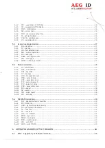
Page 3: ...ollision 33 5 5 3 KM key mode 33 5 5 4 KT key type 33 5 5 5 LOG transponder log in 34 5 5 6 PBU purse backup 34 5 5 7 PDC purse decrement 35 5 5 8 PIC purse increment 36 5 5 9 PIV purse init value 37 5 5 10 PRV purse read value 37 5 5 11 RQ request 38 5 5 12 SE select 38 5 5 13 SE2 select level 2 38 5 5 14 WK write key 39 5 6 ISO 15693 instructions 40 5 6 1 AFI application family identifier 40 5 6...

Page 4: ... 4 50 6 2 MD 0 Continuous Reading 45 7 STARTUP AND TESTING THE READER 46 8 INSTRUCTIONS 47 9 FCC INFORMATION 48 10 HOTLINE 49 11 REVISIONS 50 ...

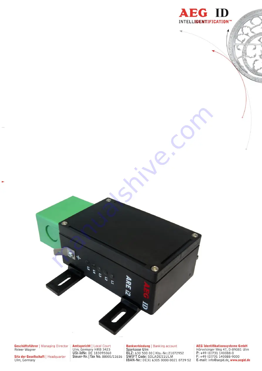
Page 5: ...ple ways for mounting the cabling concept of the reader is optimised to service demands the protection class of the housing is IP65 there is a set of external antennas available to meet special application demands X tended version 2 System overview The ARE i2 HF is only available with external antenna 3 Installation To get the specified reading performance it is necessary to do the installation ca...

Page 6: ...e most fastening elements without open the housing of the device 3 2 Grounding of the reader To get reliable reading results the reader must be grounded The connector is placed at the side of the housing 6 35 mm flat contact To avoid EMV problems the cable to ground ought to be very short with low impedance Attention The topology of the ground wires must be done in the right way according state of...

Page 7: ...asten the SAB Cab with the help of the screws To meet the protection class of IP 65 it s necessary to apply a turning moment of 0 5 Nm to the screws 3 3 Connecting of the power supply cable The reader has to be supplied with 9 30V DC The minimum output power of the power supply has to be 1 2 Watt Be sure that you use the right polarity 3 3 1 Using the pc connection cable ID 70213 Power supply brow...

Page 8: ... Using a self assembled connecting cable Using the following SAB cabs you can assemble your own connecting cable ID 70211 SAB cab with 1 PG9 cable pipe ID 70215 SAB cab with 2 pre assembled cable pipes ID 70219 SAB cab without any cable pipe You can use any shielded five pole cable The allowed diameter of the cable must be in the range from 3 5 to 8mm For this case IP 65 is reached ...

Page 9: ...e SAB Cab central and at one side of the cab The o ring 3 has to be assembled proberly to the cable pipe 4 to ensure the protection class IP 65 1 2 3 4 Figure 2 Assembling of the cable pipe Bring the nut 2 of the cable pipe inside of the SAB Cab 1 To fasten the nut please use the right tool 17mm 3 3 3 2 Mounting of the cable The cable must be mounted in following steps Remove all inner parts from ...

Page 10: ...6mm and stick a covering hull to the litz wire Put the cable to the cable pipe The length of the cable coming out the SAB Cab must long enough to do all further installation steps in an easy way Stick the pipe 4 into the cable fastener 3 Stick the cable fastener 3 into the cable pipe Connect the cables into the right places of the MINI COMBICON Connectors 6 The pin assignment is shown in the figur...

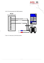
Page 11: ...gnment of the SAB connectors Figure 4 Pin assignment of the SAB connectors RS232 9 Pins Sub D female 1 2 3 4 5 6 7 8 9 RxD reader TxD reader GND US1 US1 green ARE I2 shielding V 24V GND 0V TXD RXD V DC black US2 US2 B A D C E ...

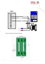
Page 12: ... 12 50 Figure 5 Pin assignment of the SAB connectors RS232 9 Pins Sub D female 1 2 3 4 5 6 7 8 9 RxD reader TxD reader GND US US grey ARE I2 shielding V 24V GND 0V TXD RXD V DC blue L U L G F J H K ...

Page 13: ...connector is on the topside of the reading device You just have to plug the antenna into the connector and bold it on Alternative you can connect an AMP 4 AMP 8 with this connector too You may not connect or deconnect an antenna or AMP 4 AMP 8 while the reader is running It can cause that the reader hangs up ...

Page 14: ... LED at the side of the housing L1 twinkles if the processor works L2 twinkles one time after successful instruction L3 twinkles one time after bad instruction L4 lit if the reader receives data s at the serial data port Rx L5 lit if the reader sends data s at the serial data port Tx Figure 6 Visual signal lamps ...

Page 15: ...sequently as 32H 35H 35H the command RST as 52H 53H 54H All numbers e g sectors blocks are in the hexadecimal format see chapter 9 With the command CS you can change to the alternative instruction set If the reader is set to alter native instruction set you can change back to the AEG ID instruction set via the command AEG see chapter 5 3 3 5 1 1 Entering instuctions The protocol format is as follo...

Page 16: ... changing a parameter After entering a valid command together with a parameter value the system answers by sending the parameter value and CR Example Command MD SP 2 CR Output 2 CR After entering an invalid parameter value the system answers with the corresponding error code Error message Command MD SP 4 CR Output NAK SP 02 CR 5 1 2 3 Output at parameter query Parameter settings can be queried by ...

Page 17: ...nticollision error level 1 NAK 12 CR anticollision error level 2 NAK 13 CR select error level 1 NAK 14 CR select error level 2 NAK 15 CR transceiver IC error NAK 16 CR not acknowlegde NAK 17 CR no valid value block NAK 18 CR EEPROM full NAK 19 CR code already saved in EEPROM NAK 20 CR Decoder communication error NAK 21 CR wrong standard NAK 22 CR wrong transpondercode length NAK 23 CR transponderc...

Page 18: ...cannot be changed locked NAK 47 CR ISO 15693 error 13h not successfully programmed NAK 48 CR ISO 15693 error 14h not successfully locked NAK 49 CR ISO 15693 error A0h DFh custom error codes NAK 50 CR all other ISO 15693 errors RFU XXXXXXXX CR no read ACK no error acknowledge 5 1 5 Upper and lower case The instruction set isn t case sensitiv 5 1 6 Linefeed The reader does never send a linefeed If y...

Page 19: ... Parameter PARAMETER FUNCTION 0 4800 baud 1 9600 baud 2 19200 baud 3 38400 baud 4 57600 baud 5 115200 baud 5 2 2 RE read EEPROM You can read out the internal EEPROM with the RE command Input format RE SP parameter CR Output example FF CR Parameter PARAMETER FUNCTION 0000h 079Fh address 5 2 3 RF radio frequency With the command RF you can switch the antenna field on and off Input format RF SP param...

Page 20: ...ter PARAMETER FUNCTION 0 off 1 on 5 2 4 RST reset With the command RST the reader does a warmstart and loads the saved settings from the internal EEPROM The antenna field is off after the reset Input format RST CR Output example ACK CR ...

Page 21: ...ROM Input format WE SP parameter 1 SP parameter 2 CR Output example FF CR Parameter PARAMETER 1 FUNCTION 0005h 079Fh address PARAMETER 2 FUNCTION 00h FFh data 5 2 6 VER version With the command VER the reader sends the actual firmware version Input format VER CR Output example AEG ID V1 22 CR ...

Page 22: ...ession 1 Suppression of error codes 5 3 2 CID suppression of ID Codes In the MD0 mode with CID 1 only the first of in succession identical transponder numbers is output on the serial interface The possibly following identical transponder numbers are suppressed as long as no new valid transponder number is received processed and output The get tag command is not influenced by this command NoReads d...

Page 23: ...ne RST CR after entering the command line CID SP 1 CR This causes that the next transponder code is output definitely Note The filter function CID picks up the results of the complete reading cycles while the parameter NID proceeds from the results of single readings The filter function CID has effect on the serial in terface only 5 3 3 CN suppression of No Reads Through the setting CN 1 the NoRea...

Page 24: ...he bytes from a transpondercode Input format MC CR Output example 0 CR 5 3 6 TOR maximum reading time Timeout time for the reader TOR is used in operation mode 2 as maximum gating time for a reading process The length of the maximum gating time results from the equation gating_time TOR TB The time constant TB time base has always the default value 100ms Input format TOR SP parameter CR Output exam...

Page 25: ...s save With the command VSAVE the following parameters are saved to the internal EEPROM AFI2 KM1 KT1 MD SI TOR Input format VSAVE CR Output example ACK CR 1 just available in the ISO 14443A standard 2 just available in the ISO 15693 standard 5 3 9 VS variables show With the command VS the reader shows the settings of the following parameters AFI2 KM1 KT1 MD SI TOR Input format VS CR Output example...

Page 26: ... 26 50 Note The function VS shows just the settings that are used in the actual ISO standard 1 just available in the ISO 14443A standard 2 just available in the ISO 15693 standard ...

Page 27: ...QA anticollision level 1 select 1 anticollision level 2 select 2 The reader answers the UID of an active non halt transponder The length of the UID can be be tween 4 and 7 bytes Input format GA CR Output example 625E562A CR 5 4 2 GT get tag With the command GT you select a transponder The command GT causes one reading cycle There are different cycles for different transpondertypes Mifare standard ...

Page 28: ...o modes of operation available It is possible that the reader reads constantly or triggered by an instruction Input format MD SP parameter CR Output example 2 CR Parameter PARAMETER FUNCTION 0 constant reading mode 2 single reading mode 5 4 5 RD read page With the command RD you can read out a page of the transponder The command executes internally the commands get tag if using mifare 1K 4K log in...

Page 29: ... data mifare 1K 4K 8 characters data ultralight up to 64 charac ters data ISO 15693 5 4 6 RDM read page manual With the command RDM you can read out a page of the transponder The reading command is executed single You have to do a get tag first If you are using a mifare standard 1K 4K you have to log in too Input format mifare 1K 4K RD SP parameter 1 SP parameter 2 CR Input format ultralight RD SP...

Page 30: ...ta ISO 15693 5 4 7 WD write page With the command WD you write one page to the transponder The command executes internally the commands get tag log in with the key attuned to KM and the writing command Input format mifare 1K 4K WD SP parameter 1 SP parameter 2 SP parameter 3 CR Input format ultralight WD SP parameter 2 SP parameter 3 CR Input format ISO 15693 WD SP parameter 2 SP parameter 3 CR Ou...

Page 31: ...k size or a multiple of the block size 5 4 8 WDM write page manual With the command WDM you write one page to the transponder The writing command is executed alone You have to select the transponder first If you are using a mifare standard 1K 4K you have to log in too Input format mifare 1K 4K WD SP parameter 1 SP parameter 2 SP parameter 3 CR Input format ultralight WD SP parameter 2 SP parameter...

Page 32: ...racters ultralight up to 32 charac ters ISO 15693 Note The ISO 15693 regulates just the maximum length of one block With the write instruction you can write multiple blocks at once The datalenght has to be at least the block size or a multiple of the block size ...

Page 33: ...collision level 2 command Input format AC2 CR Output example 595B1B80 CR 5 5 3 KM key mode With the command KM you switch the key that is used by the commands RD and WD It is possible to use the default key or one of the keys saved with the command WK Input format KM SP parameter CR Output example parameter CR PARAMETER FUNCTION 0 use default key FFFFFFFFFFFF 1 8 use saved key 1 to 8 5 5 4 KT key ...

Page 34: ...utput example ACK CR Parameters PARAMETER 1 FUNCTION A or B type of the key PARAMETER 2 FUNCTION 1 or 2 characters sector PARAMETER 3 FUNCTION 12 characters key 5 5 6 PBU purse backup With this command it is possible to copy a purse value to an other block of the same sector This com mand is only valid with mifare standard 1K 4K You have to log in first Input format PBU SP parameter 1 SP parameter...

Page 35: ...ess 5 5 7 PDC purse decrement With this command you can decrement a value This command is only valid with mifare standard 1K 4K You have to log in first Input format PDC SP parameter 1 SP parameter 2 SP parameter 3 CR Output parameter 4 SP parameter 5 CR Parameters PARAMETER 1 FUNCTION 1 or 2 characters sector PARAMETER 2 FUNCTION 1 character block PARAMETER 3 FUNCTION 8 characters value change ...

Page 36: ...alid with mifare standard 1K 4K You have to log in first Input format PDC SP parameter 1 SP parameter 2 SP parameter 3 CR Output parameter 4 SP parameter 5 CR Parameters PARAMETER 1 FUNCTION 1 or 2 characters sector PARAMETER 2 FUNCTION 1 character block PARAMETER 3 FUNCTION 8 characters value change PARAMETER 4 FUNCTION 8 characters new purse value PARAMETER 5 FUNCTION 2 character optional addres...

Page 37: ...arameters PARAMETER 1 FUNCTION 1 or 2 characters sector PARAMETER 2 FUNCTION 1 character block PARAMETER 3 FUNCTION 8 characters value PARAMETER 4 FUNCTION 2 characters optional address 5 5 10 PRV purse read value With this command you can read out a value This command is only valid with mifare standard 1K 4K You have to log in first Input format PRV SP parameter 1 SP parameter 2 CR Output paramet...

Page 38: ...arameters PARAMETER FUNCTION 0 non halt transponders 1 all transponders 5 5 12 SE select The command SE selects that transponder that answered at the anticollision For ultralight and DESFire transponders it is select level 1 command Input format SE CR Output example ACK CR 5 5 13 SE2 select level 2 The command SE2 selects that transponder that answered at the anticollision level 2 For ultralight a...

Page 39: ...d WK you save a key to the EEPROM You can save 8 different keys It is not possible to read out the saved keys Input WK SP parameter 1 SP parameter 2 CR Output example ACK CR Parameters PARAMETER 1 FUNCTION 1 8 key number PARAMETER 2 FUNCTION 12 characters 6 byte key ...

Page 40: ... application identifier are read 5 6 2 BS block size With the command BS you can choose the block size of the used transponder If the ISO 15693 tran sponders support the get system information command the parameter BS is not used Only if there is no information of the block size of the transponder available the parameter regulates the reading pro cess The block size is defined in the ISO 15693 e g...

Page 41: ... block is locked 5 6 4 GS get system information This command sends the get system information to the transponder The answer format is described in the ISO 15693 chapter 9 3 12 You have to do a get tag first Input format GS CR Output example 0F7FAA9006000104E000201B0301 CR 5 6 5 LA lock AFI This command locks the AFI of a transponder You have to do a get tag first Input format LA CR Output example...

Page 42: ... read This command reads one page of an Infineon my d transponder You have to do a get tag first Input format MDR SP parameter CR Output example 0123456701234567 CR Parameter PARAMETER FUNCTION 0h FFh page 5 6 9 MDW my d write This command writes one page of an Infineon my d transponder You have to do a get tag first Input format MDW SP parameter 1 SP parameter 2 CR Output example ACK CR Parameter...

Page 43: ... 6 11 WA write AFI With this command the reader writes the AFI into the transponder You have to do a get tag first Input format WA SP parameter CR Output example ACK CR Parameter PARAMETER FUNCTION 00h FFh AFI 5 6 12 WDS write DSFID With this command the reader writes the DSFID into the transponder You have to do a get tag first Input format WDS SP parameter CR Output example ACK CR Parameter PARA...

Page 44: ...te WD just in mode MD2 capter 8 In operating mode 2 the exciter is always turned off Triggered by the software command GT RD WD the exciter is activated After successful reading or writing of a transponder number the exciter is turned off automatically Figure 7 Software triggered reading operation If the first reading cycle yields no result NoRead the on time of the exciter is limited by the param...

Page 45: ... continuously the exciter is switched on permanently The reading cycles are initiated periodically After an accomplished reading cycle the reading information is evaluated After that data either tran sponder number or NoRead code is output to the serial interface Figure 9 continuous operation exciter processor interface TOR GT reading process NoRead reading cycle reading cycle reading cycle excite...

Page 46: ... data bits 1 start bit und 1 stop bit no parity check often called 8N1 baud rate 19200 baud no flow control e g XOFF XON Send the command VER CR to the reader The reader answers with the actual firmware version e g AEG ID V1 23 Send the command MD SP 0 CR to the reader The reader sends No Read messages e g FFFFFFFFFF or XXXXXXXXXX while there is no transponder in the antenna field available The re...

Page 47: ...orientation between reader and transponder must be well suited The best orientation depends on the type of antenna inside of the housing ferrite type or plane coil type and the applied transponder To get a reliable readings or writings the time of transponder while crossing the sensitive area of the antenna must be coordinated to the data transfer characteristics of transponder In general the time...

Page 48: ...antee that interference will not occur in a particular installation If this equipment does cause harmful interference to radio or television reception which can be determined by turning the equipment off and on the user is encouraged to try to correct the interfer ence by one or more of the following measures Reorient or relocate the receiving antenna Increase the separation between the equipment ...

Page 49: ... 49 50 10 Hotline If there are questions or suggestions please call the hotline Sales und Marketing 49 0 731 140088 0 Fax 49 0 731 140088 9000 e mail sales aegid de http www aegid de ...

Page 50: ...ith external antenna 19 08 11 Revision 02 AMP errorcode added 17 12 12 Revision 03 Command BS block size added Command BD baudrate added 18 05 16 Revision 04 FCC Information 13 12 16 Revision 05 pin assignment ARE 016 28 08 18 Revision 06 power supply minimum 29 08 18 Revision 07 my d commands added FW ...

Reviews: