


IDUN Housing
1
1
Introduction
This installation guide describes the features of the IDUR housing and tells
you how to install the basic system components such as disk drives, system
board, or expansion boards. Descriptive illustrations accompany the
installation procedures.
If you receive a complete system, the basic
components are already installed.
2
Positioning the System Housing
2.1
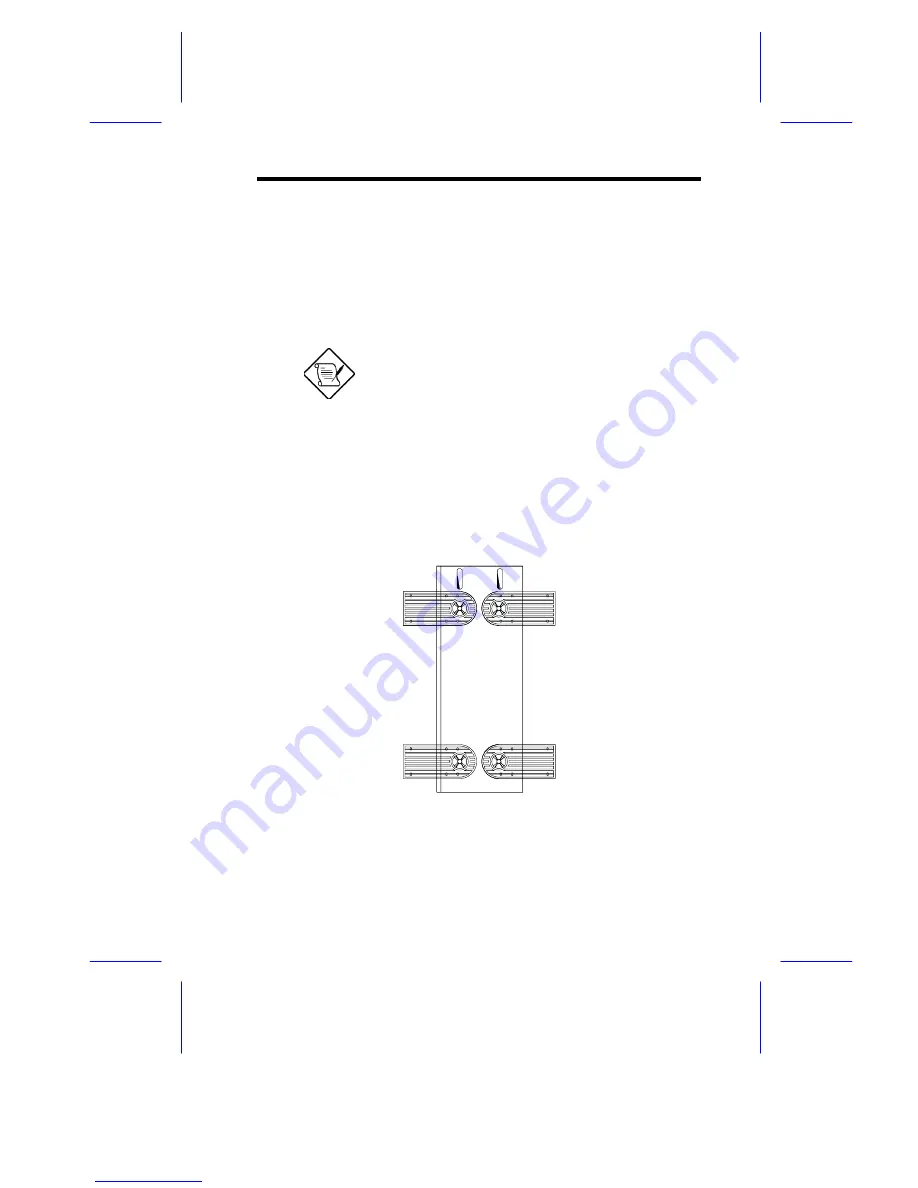
Standalone System
For a standalone system, rotate the legs outward to stabilize the housing.
Summary of Contents for IDUR
Page 28: ...28 Installation Guide 11 Connecting External Devices 11 1 Connecting a Monitor ...
Page 29: ...IDUN Housing 29 11 2 Connecting a Keyboard ...
Page 30: ...30 Installation Guide 11 3 Connecting a Mouse ...
Page 31: ...IDUN Housing 31 11 4 Connecting a Printer ...
Page 32: ...32 Installation Guide 12 Complete System Connections ...


