background image

Acer DynaVivid Graphics Dock

Service Guide

    
                                                                                                                                     PRINTED IN TAIWAN

Service guide files and updates are available

on the ACER/CSD web; for more information, 

please refer to 

http://csd.acer.com.tw

Summary of Contents for DynaVivid Graphics Dock

Page 1: ...Acer DynaVivid Graphics Dock Service Guide PRINTED IN TAIWAN Service guide files and updates are available on the ACER CSD web for more information please refer to http csd acer com tw ...

Page 2: ...ii Revision History Please refer to the table below for the updates made on this service guide Date Chapter Updates ...

Page 3: ...tations or warranties either expressed or implied with respect to the contents hereof and specifically disclaims any warranties of merchantability or fitness for any particular purpose Any Acer Incorporated software described in this manual is sold or licensed as is Should the programs prove defective following their purchase the buyer and not Acer Incorporated its distributor or its dealer assume...

Page 4: ... bits and pieces of additional information related to the current topic WARNING Alerts you to any damage that might result from doing or not doing specific actions CAUTION Gives precautionary measures to avoid possible hardware or software problems IMPORTANT Reminds you to do specific actions relevant to the accomplishment of procedures ...

Page 5: ... NOT be covered in this generic service guide In such cases please contact your regional offices or the responsible personnel channel to provide you with further technical details 2 Please note WHEN ORDERING FRU PARTS that you should check the most up to date information available on your regional web or channel If for whatever reason a part number change is made it will not be noted in the printe...

Page 6: ...vi ...

Page 7: ...moving the Mainboard 17 Removing the Thermal Module 18 Main Unit Reassembly Process 19 Replacing the Thermal Module 19 Replacing the Mainboard 20 Replacing the I O Board 21 Replacing the Upper Cover 22 Replacing the Monitor Mount 24 Replacing the Stand 25 Troubleshooting 27 Power On Issue 28 USB Failure 29 CRT Failure 30 HDMI Failure 31 Other Function Fail 32 Connector Locations 33 Mainboard Top V...

Page 8: ...viii ...

Page 9: ... 65 W AC adapter SI O interface Six USB ports HDMI port HDCP supported external display VGA port DC in jack for AC adapter Acer DynaVivid Graphics Dock connector Environment Temperature Operating 5 C to 35 C Non operating 20 C to 65 C Humidity non condensing Operating 20 to 80 Non operating 20 to 80 NOTE The specifications listed above are for reference only The exact configuration of the graphics...

Page 10: ...96 XT USB HUB IC FCBGA 962pin LASSO CONNECTOR ATi CH B PCI E x8 CRT HDMI USB DDR3 64M 16 CH A DDR3 64M 16 DDR3 64M 16 DDR3 64M 16 DDR3 64M 16 DDR3 64M 16 DDR3 64M 16 DDR3 64M 16 CRT CONNECTOR HDMI FPC CONN USB USB USB USB USB CONNECTOR ...

Page 11: ...inition digital video connections 2 External display VGA port Connects to a display device e g external monitor LCD projector 3 Acer DynaVivid Graphics Dock connector Connects to Acer DynaVivid Graphics Dock 4 DC in jack Connects to an AC adapter 5 Kensington lock slot Connects to a Kensington compatible computer security lock No Icon Item Description 1 USB 2 0 ports Connects to USB 2 0 devices HD...

Page 12: ...ered and air can freely flow through the grill Base View 2 Ventilation Slots Air flow grill No Icon Item Description 1 Kensington lock slot Connects to a Kensington compatible computer security lock 2 Lock hole Secures the device to the stand No Icon Item Description 1 2 ...

Page 13: ... SPL Spec dBA 46 3200 31 56 3700 35 65 4200 38 72 4800 46 85 95 Duty 90 Item Specification USB Hub GL852 Features Compliant to USB specification Revision 2 0 On chip 8 bit micro processor Multiple Transaction translator MTT Each downstream port supports two color status indicator Supports both individual and gang modes Supports gang mode of power management and over current detection for downstrea...

Page 14: ...6 Chapter 1 ...

Page 15: ... to avoid mismatch when putting back the components Related Information The product previews seen in the disassembly procedures may not represent the final product color or configuration IMPORTANT Cable paths and positioning may not represent the actual model During the removal and replacement of components ensure all available cable channels and clips are used and that the cables are replaced in ...

Page 16: ...e the inside assembly frame in that order Main Screw List Main Unit Disassembly Process IMPORTANT Cable paths and positioning may not represent the actual model During the removal and replacement of components ensure all available cable channels and clips are used and that the cables are replaced in the same position NOTE The product previews seen in the disassembly procedures may not represent th...

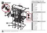
Page 17: ...Chapter 2 9 Screw List Step Screw Quantity Part No Main Unit Disassembly 2 6 15 ...

Page 18: ...10 Chapter 2 Removing the Stand 1 Slide the stand off the base of the graphics dock ...

Page 19: ...tor Mount 1 Lay the graphics dock with monitor mount down with the monitor mount underneath 2 Slide back the monitor mount lock to the open position 1 and firmly lift up the graphics dock 2 3 Repeat step 2 on the other side 2 1 1 2 ...

Page 20: ...12 Chapter 2 4 Lift the graphics dock away from the monitor mount ...

Page 21: ...emoving the Monitor Mount on page 11 1 Remove the one 1 screw 2 Insert a plastic tweezer end or other soft tool to lever open the upper cover from the lower cover in the side location shown NOTE Ensure to open in the middle of the side as there are latches to either side of the location Step Size Quantity Screw Type Removing the Upper Cover M2 6 1 ...

Page 22: ...14 Chapter 2 3 Pry up both corners of the side opened 4 Proceed to pry open the upper cover around the edges of the graphic dock 5 Lift the upper cover off ...

Page 23: ...Chapter 2 15 Removing the I O Board 1 See Removing the Upper Cover on page 13 2 Remove the I O cable 3 Remove the four 4 screws Step Size Quantity Screw Type Removing the IO board M2 6 4 ...

Page 24: ...16 Chapter 2 4 Lift the I O board out ...

Page 25: ...e Mainboard 1 See Removing the Upper Cover on page 13 2 See Removing the I O Board on page 15 3 Remove the ten screws 10 from the mainboard 4 Lift the mainboard out Step Size Quantity Screw Type Removing the Mainboard M2 6 10 ...

Page 26: ...pter 2 Removing the Thermal Module 1 See Removing the Mainboard on page 17 2 Remove the thermal module cable 3 Loosen the four captive screws in order first 4 then 3 2 1 4 Lift the thermal module out 1 2 3 4 ...

Page 27: ...nit Reassembly Process Replacing the Thermal Module 1 Place the thermal module on the mainboard 2 Tighten the four captive screws in order first 1 then 2 3 4 3 Connect the thermal module connector to the mainboard 1 2 3 4 ...

Page 28: ...20 Chapter 2 Replacing the Mainboard 1 Place the mainboard into the lower cover 2 Replace the ten 10 screws Step Size Quantity Screw Type Replacing the Mainboard M2 6 10 ...

Page 29: ...Chapter 2 21 Replacing the I O Board 1 Place the IO board into the lower cover 2 Replace the four 4 screws Step Size Quantity Screw Type Replacing the IO board M2 6 4 ...

Page 30: ...22 Chapter 2 3 Replace the IO cable Replacing the Upper Cover 1 Place the upper cover on the lower cover being careful to align the latch correctly ...

Page 31: ...Chapter 2 23 2 Press down around the edges of the upper cover firmly 3 Replace the one 1 screw Step Size Quantity Screw Type Replacing the Upper Cover M2 6 1 ...

Page 32: ...cing the Monitor Mount 1 Place the graphics dock onto the monitor mount 2 Slide the monitor mount latch switch open 1 and press the graphics dock down 2 until it latches in place 3 Repeat Step 2 on the other side 1 2 1 2 ...

Page 33: ...Chapter 2 25 Replacing the Stand 1 Slide the stand onto the graphics dock mounting bracket ...

Page 34: ...26 Chapter 2 ...

Page 35: ... symptoms in as much detail as possible 2 Verify the symptoms by attempting to re create the failure by running the diagnostic test or by repeating the same operation 3 Use the following table with the verified symptom to determine which page to go to 4 If the issue is still not resolved see Online Support Information on page 43 Symptoms Verified Go To Power On Issue Page 28 USB Failure Page 29 CR...

Page 36: ...and the outlet 3 Remove any surge protectors between the graphics dock and the electrical outlet Plug the graphics dock directly into a known good electrical outlet 4 Remove all external and non essential hardware connected to the graphics dock that are not necessary to the graphics dock 5 If the Issue is still not resolved see see Online Support Information on page 43 Swap M B Start Check Lasso c...

Page 37: ...following actions one at a time to correct the problem Do not replace non defective FRUs Start Check USB B to M B FPC Re assemble the USB B FPC OK NG Check USB B Swap USB B OK NG Swap M B Check USB B to M B FPC Re assemble the USB B FPC OK NG Check USB B Swap USB B OK NG Swap M B ...

Page 38: ...wer on perform the following actions one at a time to correct the problem Do not replace non defective FRUs Re assembly Swap CRT cable Swap M B Start Check CRT cable Check MB CRT connector OK NG OK NG Check CRT cable Check MB CRT connector OK NG OK NG ...

Page 39: ...the following actions one at a time to correct the problem Do not replace non defective FRUs Start Swap M B Check HDMI cable Re assemble Swap HDMI cable OK NG Check M B HDMI connector OK NG Check HDMI cable Re assemble Swap HDMI cable OK NG Check M B HDMI connector OK NG ...

Page 40: ... noted perform the following actions one at a time to correct the problem Do not replace non defective FRUs Start Check Driver is latest Check test fixture Swap M B Update driver to latest OK No Fix test fixture OK NG Update driver to latest OK No Fix test fixture OK NG ...

Page 41: ...Chapter 4 33 Connector Locations Mainboard Top View Connector Description Connector Description U34 VRAM U32 VRAM U24 VRAM CN9 FCC Connector U25 VRAM Chapter 4 ...

Page 42: ...34 Chapter 4 Mainboard Bottom View Connector Description Connector Description U1 M96 M2 U21 VRAM CN14 Fan Connector U28 VRAM CN15 CRT U31 VRAM CN1 Lasso Connector U33 VRAM PJ1 DC Jack ...

Page 43: ...easons a part number change is made it will not be noted on the printed Service Guide For ACER AUTHORIZED SERVICE PROVIDERS your Acer office may have a DIFFERENT part number code from those given in the FRU list of this printed Service Guide You MUST use the local FRU list provided by your regional Acer office to order FRU parts for repair and service of customer machines NOTE To scrap or to retur...

Page 44: ...apter 5 Acer DynaVivid Graphics Dock Exploded Diagrams Main Assembly Item Description Part Number 1 Upper Cover 2 Lower Cover 3 Monitor Mount 4 Stand 5 Thermal Module 6 Thermal Bracket 7 IO Board 8 Mainboard ...

Page 45: ...Chapter 5 37 FRU List CATEGORY PARTNAME ACERPARTNO ADAPTER AP 06501 026 AP 06503 024 AP 0650A 012 BOARD CABLE POWER CORD US 3PIN ROHS 27 TAXV7 001 CASE COVER BRACKET ASSEMBLY ...

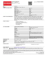
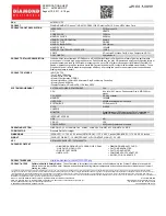
Page 46: ...38 Chapter 5 MAINBOARD HEATSINK SCREW CATEGORY PARTNAME ACERPARTNO ...

Page 47: ... N A N A N A P N A P P D Sub 1920x1080 60Hz P P P P P N A N A N A N A N A N A P N A P P DVI 1920x1080 60Hz N A N A N A N A N A N A N A N A N A N A N A N A N A N A N A D Sub 1920x1080 60Hz P P P P P N A N A N A N A N A N A P N A P P DVI 1920x1080 60Hz N A N A N A N A N A N A N A N A N A N A N A N A N A N A N A HDMI 1920x1080 60Hz P P P P P N A N A N A N A N A N A P N A P P 24 H243H x 23 Viseo 223Ws...

Page 48: ...P Na P P DVI 1920x1080 60Hz Na Na Na Na Na Na Na Na Na Na Na Na Na Na Na D Sub 1920x1080 60Hz P P P P P Na Na Na Na Na Na P Na P P DVI 1920x1080 60Hz Na Na Na Na Na Na Na Na Na Na Na Na Na Na Na HDMI 1920x1080 60Hz Na Na Na Na Na Na Na Na Na Na Na Na Na Na Na 24 H243H x 21 H223HQ v 23 Viseo 223Ws v X233H x B233HU t V243HQ t 19 X193HQ x Viseo 193Ws v 20 V203H v Fn F5 Driver Utility Issue Descriptio...

Page 49: ...ve XGA 1024x768 60Hz P P P P P Na Na Na Na Na Na P P P P D Sub Native XGA 1280x800 60Hz P P P P P Na Na Na Na Na Na P P P P DVI Native XGA 1280x800 60Hz Na Na Na Na Na Na Na Na Na Na Na Na Na Na Na HDMI Native XGA 1280x800 60Hz P P P P P Na Na Na Na Na Na P P P P P1266i P5280 P7270i P5370W P3250 H5350 S1200 Acer Projector vs NB External Single mode Fn F5 Driver Utility Model Name Input Native Reso...

Page 50: ......

Page 51: ...n on all of Acer s Graphic Docks Notebook Desktop and Server models including Service guides for all models User s manuals Training materials Bios updates Software utilities Spare parts lists TABs Technical Announcement Bulletin For these purposes we have included an Acrobat File to facilitate the problem free downloading of our technical material Also contained on this website are Detailed inform...

Page 52: ...44 Appendix B ...

Page 53: ...tor Locations 33 L LCD Module Disassembly Flowchart 19 M Main Unit Disassembly Flowchart 8 Mainboard Removing 17 20 Memory Check 28 29 O Online Support Information 43 P Panel 3 Power On Failure 28 29 S System Block Diagram 2 T Test Compatible Components 39 Thermal Module Removing 18 19 Troubleshooting Power On 28 29 U Upper Cover Removing 10 13 W Windows 2000 Environment Test 39 Index ...

Page 54: ...46 ...

Page 55: ...47 ...

Page 56: ...48 ...

Reviews: