background image


ACER 


  HEAVY DUTY PRECISON 

ENGINE LATHE 


Model:    Dynamic 3370X~33330X 

Dynamic 3770X~37330X 


Dynamic 4170X~41330X 

OPERATION MANUAL 

& PART LISTS 

 
Taiwan: Ya-Gin Machine Tool Manufacturing Inc. 
 

  Ya-Wei Machine Tool Manufacturing Inc. 


  No. 101, 506 Lane, Seng-Tso Road 


  Seng Karng District, Taichung City, Taiwan 


  Tel: 886-4-2520-4120   

Fax: 886-4-2520-4123 

 
CA: Springwood Industrial, Inc. 
 

2320 E. Valencia Drive, Fullerton, CA 92831 USA 


Tel: 714-871-5558   

Fax: 714-871-5554 

 
NJ: Klim Industrial, Inc. 
 

244 N. Randolphville Rd, Piscataway, NJ 08854 USA 


Tel: 732-752-9100   

Fax: 732-752-9101 


Revised: 1/14/20 


Summary of Contents for Dynamic 3370X

Page 1: ...Inc Ya Wei Machine Tool Manufacturing Inc No 101 506 Lane Seng Tso Road Seng Karng District Taichung City Taiwan Tel 886 4 2520 4120 Fax 886 4 2520 4123 CA Springwood Industrial Inc 2320 E Valencia Drive Fullerton CA 92831 USA Tel 714 871 5558 Fax 714 871 5554 NJ Klim Industrial Inc 244 N Randolphville Rd Piscataway NJ 08854 USA Tel 732 752 9100 Fax 732 752 9101 Revised 1 14 20 ...

Page 2: ... UNPACKING MACHINE INSTALLATION 3 1 Unpacking Lifting 3 2 Basic Foundation 4 MAJOR CONSTRUCTION 4 1 Headstock 4 2 Spindle 4 3 Spindle Speed Selection 4 4 Carriage Slide 4 5 Tailstock 4 6 Apron 4 7 Gear Box 4 8 Thread Chasing Dial 4 9 Steady Rest 4 10 Brake System 5 LUBRICATION 5 1 Headstock Lubrication 5 2 Gear Box Apron Lubrication 5 3 Lubrication Charts 5 4 Lubrication Location ...

Page 3: ... 6 6 Brake Micro Switch Adjustment 6 7 Cutting Coolant Repair 7 MECHANICAL PART LISTS 7 1 Headstock Assembly 7 2 Gear Box Assembly 7 3 Gear Box Cover Assembly 7 4 Apron Assembly 7 5 Machine Bed and Base Assembly 7 6 Brake System 7 7 Carriage and Crossfeed System 7 8 Tailstock 7 9 Chip Guard 7 10 Leadscrew Cover and Rear Splash Guard ...

Page 4: ...nstructions in the manual Any damage of the machine and injury on the worker caused by improper operation and disregard of our instruction is not covered under warranty In addition to the instructions listed in our manual there are some matters needing attention as well 1 Do not expose the machine to outdoors in order to avoid any damage caused by the weather and must keep the machine away from co...

Page 5: ...5 1 Machine Assembly ...

Page 6: ... 25 Jog button 8 Compound rest handle 26 Half nut engaged lever 9 Tailstock body 27 Longitudinal feed hand wheel 10 Tailstock set over adjusting Screw 28 Auto feeding engaged lever 11 Tailstock body clamping screw 29 Apron hand wheel 12 Tailstock spindle locking lever 30 Foundation adjusting bolt 13 Spindle speed shifting lever 31 Foot brake pedal 14 Tailstock hand wheel 32 Lead screw 15 Spindle s...

Page 7: ...hine must have a ground wire Fig 2 1 2 2 Electrical Equipment 1 The electrical cabinet is also equipped with overload circuit breakers and electric magnetic contactors to protect motors from overload during excess heavy cutting 2 The forward reverse switch is connected with micro switch 3 The foot brake is connected with micro switch Stepping the footbrake is quicker to stop the lathe than turning...

Page 8: ... by interchanging any two of the three phase lines R S T in the power source 2 Checking each lubrication system s oil level 3 Checking each handle if it is function normally 4 Checking belt tension adjustment to see if it is in good condition 5 Read and understand each section of the lathe before operation 6 When power indicator is ON but spindle motor is not running Overload circuit breaker and e...

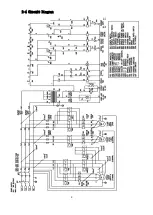
Page 9: ...9 2 4 Circuit Diagram ...

Page 10: ...Low speed revolution 12 Electrical control cabinet 3 Forward revolution 13 THREADS Imperial threads 4 N Neutral gear 14 mm Metric threads 5 Reverse revolution 15 mm Auto feeding rate per revolution 6 Feeding 16 Coolant pump 7 T Jog 17 GREEN Power switch ON 8 Cross feeding 18 RED Power switch OFF 9 Longitudinal feeding 19 OIL Oil inlet hole 10 Cone clutch ...

Page 11: ... to below picture for machine unloading from the truck moving The steps for lifting the lathes are 1 Clamp the bed way with a special made hanger and bars through the base holes which consists of a clamp and an iron chain 2 Raise the lathe a little bit with crane and then check if the lathe is balanced If not move apron and cross slide back or forth to make sure the machine is balanced 3 While the...

Page 12: ...o establish the best cutting condition it is necessary to build a sound good floor foundation Adjust the leveling by adjustable screws and nut locks and build the angled screws within the foundation concrete Model A BxN C Model A BxN C 3370 1430 0 0 33210 965 1000x3 965 3390 965 0 965 33250 965 1000x4 965 33130 965 1000x1 965 33290 965 1000x5 965 33170 965 1000x2 965 33330 965 1000x6 965 ...

Page 13: ...recision grinding and will reduce friction noise and increase wear resistant 2 Spindle speed with 12 steps speed change the device included circular speed plate three range shift lever and the shift lever control reversed and forward Please only change the spindle speed after stopping the spindle Otherwise the gears will get damaged And will resulting in noise and vibration on the lathe and reduct...

Page 14: ...t end of two ultra precision taper roller bearings and back end using a deep groove ball bearing can withstand heavy load heavy cutting and enable precision turning purposes 3 To adjust the two taper roller bearings backlash please loosen the set screws on the adjust nuts first and then turn the adjust nuts according to requirement Spindle structure ...

Page 15: ...le speed table Select the speed range L M or H Example To select 680 rpm shift the speed shifting lever to H position first and then rotate the spindle speed shifting selection lever to the position 680 2 In order to shift the speed levers easier please press the jog button momentarily ...

Page 16: ...urface 3 Taper cutting Cross carriage engraved with the angle indicator when doing taper cutting please loosen the locking screws B and rotate the compound rest to the angle you need and then lock screws B tightly before cutting start 4 Adjustment of the gibs To avoid the gap caused by the long period wearing and tearing of sliding surfaces a gib for possible adjustments to eliminate the gap in ea...

Page 17: ...cated next to the speed control box please operate transmission shift handle and then turning the hand wheel tailstock spindle to do 1 to 1 or 1 to 4 fast slow moving for drilling feed and backward 2 2 Shaft clamp spindle fixed the tailstock center 2 3 Clamping plate for fix the tailstock tightly on lathe bed 2 4 When the center of tailstock center sleeve and spindle are not on the same level line...

Page 18: ...te the automatically feed lever down to engage the feed There is protection stop device under the apron of longitudinal feeding to automatically stop To adjust the distance loosen the stop feeding ring on the mounting screws move the stop feeding ring to the desired position then fix 3 Thread cutting drive When doing the split nut lever down operation split nut will combine with the lead screw and...

Page 19: ...utting please press the stop button in the middle For emergency stop please press Emergency Stop 6 There is an operation box with control panel at the right hand side of the apron 7 Left side buttons on the control panel are spindle forward reverse and jog button To control the spindle forward and backward press the start button and start cutting If operator wants to stop cutting press the stop bu...

Page 20: ...hread cutting and automatic feed for cutting inch or metric thread but still can be cut DP and Module thread without changing any gear 3 The thread cutting please follow the instructions thread cutting chart of various gear lever placed in the appropriate position in order to cut the require thread pitch 4 Automatic feed please follow the thread cutting chart in section 4 8 depending on the desire...

Page 21: ...4 times 4 Cutting thread is even thread may be aligned at an angle of any tick of 8 times Metric with 10T 11T 12T 13T 14T of the Worm gear 1 Cutting thread of 0 8 1 0 1 2 table data use the worm gear 12T any angle can be aligned with the mark total 8 times 2 Cutting thread of 0 9 2 25 table data use the worm gear 12T any angle can be aligned with any four angles of the mark such as 1 2 3 4 total 4...

Page 22: ...ligned with a single mark repeat the original single point cutting until done only once 7 Cutting thread of 1 3 3 25 table data use the worm gear 13T can be aligned with single mark repeat the original single point cutting until done only once Thread Cutting Chart for X Series ...

Page 23: ...upport centering a long and flexible work piece Please tighten clamp to a proper position loosen set screw A and rotate handwheels on the 3 quills to required position Then after tighten set screw A please lubricate periodically when using roller type tips ...

Page 24: ...f immediately and motor pulley will stop running We offer foot pedal for brake with models within 3 meters between centers models above 3 meters we do not offer After stepping on the foot pedal the power will cut off immediately and brake lining and motor pulley will stop running ...

Page 25: ... oil bath type system To ensure the long service life of gear box please replace the oil in the gear box every six months 2 Apron is also an oil bath type system Add more oil as soon as the oil level is lower than the center line of the oil sight glass 5 3 Lubrication Charts No Location Methods Oil amount Oil time Exchange time Recommend oil type 1 Headstock Loosen the oil input hole screw on the ...

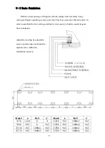
Page 26: ...26 7 Leadscrew Add oil with oil gun As required Once per day 8 Bedways Auto lubrication ...

Page 27: ...27 5 4 Lubrication Location A Oil input hole B Oil drain hole ...

Page 28: ...ral times And rotate the spindle at the same time to clean up the blocked returning oil path 3 Spindle bearing adjustment The front and middle bearings of the spindle is high precision taper roller type It is required to adjust the bearings to have suitable preload for maintaining the high accuracy and the best turning functions After long usage of the lathe the spindle lock nut may become loose a...

Page 29: ...l they are properly tightened Afterwards please re install the thread chasing dial in position 5 Adjustment for the longitudinal cross auto feeding overload Please stop the machine before doing adjustment The cone clutch on the right hand side of the apron is an overload protection device Turning clockwise the overload will increase turning anticlockwise the overload will decrease 6 3 Gear Box 1 L...

Page 30: ...hieved 3 After adjustment please be sure to tighten the adjusting nuts securely Fig 6 4 6 5 Brake Belt Adjustment If the brake belt is worn out and causes the brake band to loosen it is time to adjust the nut H on the brake band Remove the side cover loosen the nuts on the top first and tighten the nuts on the bottom to the appropriate height Then tighten the nuts on the top to complete the adjust...

Page 31: ...needs to reset and re engage the spindle operation control lever to make the spindle rotate again Fig 6 6 6 7 Cutting Coolant Repair If there is no coolant coming out after the pump switch is turned on please check the pump motor is turning or not If yes please check to see if the coolant in the tank is over the pump or not If not please add coolant and then turn on the switch if there is still no...

Page 32: ...ical Drawings Parts Breakdown List Note When ordering parts please be prepared with 1 Machine model serial number 2 Item number 3 Part number and description 4 Year of Production 5 Voltage horsepower 6 Quantity ...

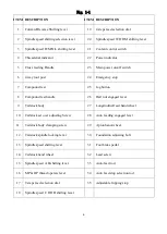
Page 33: ...33 7 1 Headstock Assembly ...

Page 34: ...30 91121030 M10xP1 25x30L 12 Cam shaft 1 5001008 5001008 5001008 13 Worm gear 12T 1 5001013 5001013 5001013 14 Square key 6x6x25L 1 91610625 91610625 91610625 15 Hexagon socket screw 6 91111025 91111025 91111025 M10xP1 25x25L 16 Worm bearing adjuster 1 5001016 5001016 5001016 17 Set screw 2 91120806 91120806 91120806 M8xP1 25x6L 18 Hob 1 5001018 5001018 5001018 19 Locating ring 1 5001019 5001019 5...

Page 35: ... bearing 6207 4 91306207 91306207 91306207 45 Gear 58T 1 5001045 5001045 5001045 46 Gear shaft 23T 1 5001046 5001046 5001046 47 Ball bearing 6208 1 91306208 91306208 91306208 48 Plug A B 2 5001048 5001048 5001048 49 O RING P70 2 9151P070 9151P070 9151P070 50 Cover 1 5001050 5001050 5001050 51 Gear 43T 1 5001051 5001051 5001051 52 Gear 61T 1 5001052 5001052 5001052 53 Square key 10x10x90L 2 9161109...

Page 36: ...110635 91110635 91110635 M6xP1 0x35L 79 Hexagon socket screw 11 91112055 91112055 91112055 M20xP2 5x55L 80 Cover 1 5001080 5001080 5001080 81 Shaft 1 5001081 5001081 5001081 82 Gear 1 5001082 5001082 5001082 83 Square key 10x10x45L 1 91611045 91611045 91611045 84 Snap ring S38 2 9171S038 9171S038 9171S038 85 Gear 42T 1 5001085 5001085 5001085 86 Lap 5 5001086 5001086 5001086 87 Dials the fingernai...

Page 37: ...all bearing 6005 1 91306005 91306005 91306005 114 Retainer G 1 5001114 5001114 5001114 115 key 6x6x25L 1 91620625 91620625 91620625 116 Output shaft 1 5001116 5001116 5001116 117 Seal oil TC 30x50x8 1 91523050 91523050 91523050 118 Ball bearing 6906 1 91306906 91306906 91306906 119 Lever 1 5001119 5001119 5001119 120 Retainer F 1 4001010 4001010 4001010 121 Snap ring S38 1 9171S038 9171S038 9171S0...

Page 38: ...me 1 5001139 5001139 5001139 140 Hexagon socket screw 2 91110515 91110515 91110515 M5xP0 8x15L 141 Hexagon socket screw 2 91110525 91110525 91110525 M5xP0 8x25L 142 Base support 1 5001141 5001141 5001141 143 Locates the base 1 5001140 5001140 5001140 144 Ball steel 1 145 Spring 1 146 Lenz oil φ 29 1 92552001 92552001 92552001 147 Set screw M5xP0 8x12L 48 91120512 91120512 91120512 148 Snap ring S4...

Page 39: ...39 7 2 Gear Box Assembly ...

Page 40: ...02011 12 KEY 6X6X50L 1 13 GEAR 1 5002013 5002013 5002013 14 GEAR 1 5002014 5002014 5002014 15 SNAP RING 1 16 BEARING 6203 1 91301016 91301016 91301016 17 GEAR 1 5002017 5002017 5002017 18 BEARING 6205 1 19 KEY 6X6X20L 1 20 SHAFT 1 5002020 5002020 5002020 21 KEY 6X6X50L 1 22 KEY 6X6X20L 1 23 BEARING 6005 1 91301010 91301010 91301010 24 GEAR 1 5002024 5002024 5002024 25 SNAP RING 1 26 GEAR 1 5002026...

Page 41: ...2 GEAR 1 5002052 5002052 5002052 53 GEAR 1 5002053 5002053 5002053 54 GEAR 1 5002054 5002054 5002054 55 GEAR 1 5002055 5002055 5002055 56 GEAR 1 5002056 5002056 5002056 57 GEAR 1 5002057 5002057 5002057 58 GEAR 1 5002058 5002058 5002058 59 GEAR 1 5002059 5002059 5002059 60 SHAFT 1 5002060 5002060 5002060 61 KEY 6X6X130L 1 62 BEARING 6204 1 91301018 91301018 91301018 63 BEARING 6204 1 91301018 9130...

Page 42: ...EAR 1 5002081 5002081 5002081 82 GEAR BOD 1 5002082 5002082 5002082 83 BEARING 6205 1 84 SNAP RING 1 85 GEAR 1 5002085 5002085 5002085 86 BEARING 6002 1 87 CLUTEH 1 5002087 5002087 5002087 88 BEARING 6006 1 89 SNAP RING 1 90 SNAP RING 1 91 BEARING 6005 1 91301010 91301010 91301010 92 COVER 1 5002092 5002092 5002092 93 BOLT M6X16L 3 91110616 91110616 91110616 94 SHAFT 1 5002094 5002094 5002094 95 L...

Page 43: ...43 7 3 Gear Box Cover Assembly ...

Page 44: ...114 15 SHAFT 1 5002115 5002115 5002115 16 BEARING 6200 1 17 GEAR 1 5002117 5002117 5002117 18 Claw shifter 1 5002118 5002118 5002118 19 SHAFT 1 5002119 5002119 5002119 20 GEAR SHAFT 1 5002120 5002120 5002120 21 SLIDE PLATE 1 5002121 5002121 5002121 22 SETTING PLATE 1 5002122 5002122 5002122 23 COVER 1 5002123 5002123 5002123 24 BOLT 1 25 Shifter 1 5002125 5002125 5002125 26 SAFT 5 5002126 5002126 ...

Page 45: ...45 7 4 Apron Assembly Right Hand ...

Page 46: ... 5003015 5003015 5003015 16 Seat worm 1 5003016 5003016 5003016 17 Shaft worm 1 5003017 5003017 5003017 18 SHAFT 1 5003018 5003018 5003018 19 BRACKET 1 5003019 5003019 5003019 20 BEARING 51103 1 21 SPRING 1 5003021 5003021 5003021 22 GEAR 1 5003022 5003022 5003022 23 Nut half 1 5003023 5003023 5003023 24 Nut half 1 5003024 5003024 5003024 25 SCREW M6X20L 2 91110620 91110620 91110620 26 REUULATOR 1...

Page 47: ...0 5003050 5003050 51 BEARING 6003 1 52 SNAP RING S40 1 9171S040 9171S040 9171S040 53 GEAR 1 5003053 5003053 5003053 54 GEAR 1 5003054 5003054 5003054 55 BEARING 6003 1 56 GEAR 1 5003056 5003056 5003056 57 COVER 1 5003057 5003057 5003057 58 COVER 1 5003058 5003058 5003058 59 SCREW M6X35L 2 91110635 91110635 91110635 60 HUB 1 5003060 5003060 5003060 61 HANDLE 1 62 SHAFT 1 5003062 5003062 5003062 63 ...

Page 48: ...3089 5003089 90 BEARING 6003 1 91 SNAP RING S20 1 9171S020 9171S020 9171S020 92 SHAFT 1 5003092 5003092 5003092 93 HANDLE 1 5003093 5003093 5003093 94 BEARING 6003 1 95 GEAR 1 5003095 5003095 5003095 96 SNAP RING R35 1 9171R035 9171R035 9171R035 97 BEARING 6003 1 98 WASHER 1 5003098 5003098 5003098 99 GEAR 1 5003099 5003099 5003099 100 BEARING 6003 1 101 SHAFT 1 5003101 5003101 5003101 102 BEARING...

Page 49: ... 91111612 91111612 119 BUSHING 1 5003119 5003119 5003119 120 BEARING 6203 1 121 PIN 1 122 SHAFT 1 5003122 5003122 5003122 123 HANDLE 1 5003123 5003123 5003123 124 COVER 1 5003124 5003124 5003124 125 GEAR 1 5003125 5003125 5003125 126 SNAP GING S12 1 9171S012 9171S012 9171S012 127 SHAFT 1 5003127 5003127 5003127 128 SPRING 1 5003128 5003128 5003128 129 SHAFT 1 5003129 5003129 5003129 130 OIL SEAL 1...

Page 50: ...50 7 4 Apron Assembly Left Hand ...

Page 51: ... 1 5003016 5003016 5003016 16 1 Seat worm left hand 5003016 001 5003016 001 5003016 001 17 Shaft worm 1 5003017 5003017 5003017 18 SHAFT 1 5003018 5003018 5003018 19 BRACKET 1 5003019 5003019 5003019 20 BEARING 51103 1 21 SPRING 1 5003021 5003021 5003021 22 GEAR 1 5003022 5003022 5003022 23 Nut half 1 5003023 5003023 5003023 24 Nut half 1 5003024 5003024 5003024 25 SCREW M6X20L 2 91110620 91110620...

Page 52: ...0616 45 Tappet 1 5003045 5003045 5003045 46 PIN 1 47 SHAFT right hand 1 5003047 5003047 5003047 47 1 SHAFT left hand 5003047 001 5003047 001 5003047 001 48 SHAFT 1 5003048 5003048 5003048 49 BRACKET 1 5003049 5003049 5003049 50 SHAFT 1 5003050 5003050 5003050 51 BEARING 6003 1 52 SNAP RING S40 1 9171S040 9171S040 9171S040 53 GEAR 1 5003053 5003053 5003053 54 GEAR 1 5003054 5003054 5003054 55 BEARI...

Page 53: ...5003071 71 1 LEVER left hand 5003071 001 5003071 001 5003071 001 72 COVER 1 5003072 5003072 5003072 73 SCREW M6X16L 3 91110616 91110616 91110616 74 HANDLE 1 5003074 5003074 5003074 75 HUB 1 5003075 5003075 5003075 76 PIN 1 5003076 5003076 5003076 77 BEARING 6203 1 78 GEAR 1 5003078 5003078 5003078 79 GEAR 1 5003079 5003079 5003079 80 BEARING 6203 1 81 SHAFT 1 5003081 5003081 5003081 82 SNAP RING S...

Page 54: ... 5003108 5003108 109 Dial rack 1 5003109 5003109 5003109 110 HAND WHEEL 1 5003110 5003110 5003110 111 HANDLE 1 5003111 5003111 5003111 112 SHAFT 1 5003112 5003112 5003112 113 BEACKET 1 5003113 5003113 5003113 114 SCREW M12X30L 1 91111230 91111230 91111230 115 GEAR SHAFT 1 5003115 5003115 5003115 116 KEY 8X7X30L 1 117 GEAR 1 5003117 5003117 5003117 118 SCREW M16X12L 1 91111612 91111612 91111612 118...

Page 55: ...55 APRON ASSEMBLY ITEM Part Name QTY Model 33 Model 37 Model 41 NO Part No Part No Part No 128 SHAFT 1 5003128 5003128 5003128 129 OIL SEAL 13246 1 130 1 131 GEAR 1 5003131 5003131 5003131 132 MOTOR 1 ...

Page 56: ...56 7 5 Machine Bed and Base Assembly ...

Page 57: ...15 5004006 015 7 Hexagon socket screw 10 91110515 91110515 91110515 M5xP0 8x15L 8 Pin taper 6x35 8 feet 2 10 feet 5 15 feet 5 9 Cover coolant 1 3004035 3004035 3004035 motor seat with socket hole motor seat without socket hole 1 3004035 001 3004035 001 3004035 001 10 Supporter shaft 1 3004010 3004010 3004010 11 Set screw 2 91120610 91120610 91120610 M6xP1 0x10L 12 Collar 1 3004012 3004012 3004012 ...

Page 58: ...g 5 3004031 3004031 3004031 34 Seat coolant pump 1 5004034 5004034 5004034 37 Bolt hexa head 2 M8x38L 40 gap 1 5004040 5004040 5004040 41 Hexagon socket screw 4 91111225 91111225 91111225 M12xP1 0x25L 42 Nut lock M6 2 43 Pin 7x40L 2 44 Hexagon socket screw 2 91111035 91111035 91111035 M10xP1 25x35L 51 Connect board 1 5004051 5004051 5004051 52 Tank cover 1 5004052 5004052 5004052 53 Cover 4 500405...

Page 59: ...59 MACHINE BED AND BASE ASSEMBLY 111 Steady block 1 5004111 5004111 5004111 112 Spring 1 5004112 5004112 5004112 113 Cover 1 5004113 5004113 5004113 ...

Page 60: ...60 7 6 Brake System ...

Page 61: ...socket screw 3 91111030 91111030 91111030 M10xP1 5x30L 12 Bracket motor seat 1 5005012 5005012 5005012 13 Bracket pedal 2 3005013 3005013 3005013 14 1 15 Pedal brake 8 feet 1 3005015 008 3005015 008 3005015 008 10 feet 1 3005015 010 3005015 010 3005015 010 15 feet 1 3005015 015 3005015 015 3005015 015 16 Shaft pedal bracket 8 feet 1 5005016 008 5005016 008 5005016 008 10 feet 1 5006016 010 5006016...

Page 62: ... 50HZ 1 5005025 001 5005025 001 5005025 001 20HP 50HZ 1 5005025 002 5005025 002 5005025 002 25HP 30hp 60HZ 1 5005025 003 5005025 003 5005025 003 26 Bracket 1 5005026 5005026 5005026 27 Key 12x12x55L 1 Key 14x14x55L 28 Motor 1 29 Bolt hexa Head 4 91111030 91111030 91111030 M10x30L ...

Page 63: ...63 7 7 Carriage and Crossfeed System ...

Page 64: ... 5006011 5006011 5006011 11 1 Wiper rear 2 5006011 001 5006011 001 5006011 001 12 Case wiper rear 4 5006012 5006012 5006012 13 Screw cross recessed 12 M4xP0 7x10L 14 Pin 2 15 Gib 1 5006015 5006015 5006015 16 Holder gib 1 5006016 5006016 5006016 17 Hexagon socket screw 8 91110820 91110820 91110820 M8xP1 25x20L 18 Set screw 5 91120825 91120825 91120825 M8xP1 25x25L 19 Nut M8xP1 25 5 22 Pin taper 6 7...

Page 65: ...1 43 2 Knob handle 1 3006043 002 3006043 002 3006043 002 44 Plug oil inlet 1 3006044 3006044 3006044 45 Lever 1 3006045 3006045 3006045 46 Screw carriage clamp 1 3006046 4006046 4006046 47 Case wiper 1 5006047 5006047 5006047 48 Wiper 1 5006048 5006048 5006048 49 Screw adjusting 2 4006049 4006049 4006049 50 Gib 1 5006050 5006050 5006050 51 Bolt hexa Socket 4 91111040 91111040 91111040 M10xP1 5x40L...

Page 66: ...076 77 Bearing thrust 51102 2 78 Seat compound rest screw 1 79 Nut 1 80 Collar 1 5006080 5006080 5006080 81 Dial compound rest 1 5006081 5006081 5006081 82 Washer wave type 1 83 Nut 1 84 Handle 1 5006084 5006084 5006084 85 Hexagon socket screw 1 91110616 91110616 91110616 M6xP1 0x16L 86 Knob handle 1 5006086 5006086 5006086 87 Hexagon socket screw 4 91111215 91111215 91111215 M12xP1 75x15L 88 Set ...

Page 67: ...67 7 8 Tailstock ...

Page 68: ...14 Plug oil 1 4 3 15 Seal oil TC120X150X14 1 16 Spindle tang slot 1 5007016 5007016 5007016 17 Cap spindle 1 5007017 5007017 5007017 18 Hexagon socket screw 4 91110816 91110816 91110816 M8xP1 25x16L 19 Screw spindle feed mm 1 5007019 5007019 5007019 20 Key square 6x6x25 1 91610606 91610606 91610606 21 Bearing thrust 51205 2 91303006 91303006 91303006 22 Indicator 1 4007022 4007022 4007022 23 Hexag...

Page 69: ...7050 51 Gear 1 4007051 4007051 4007051 54 Washer 1 3007054 3007054 3007054 55 Spacer 1 5007055 5007055 5007055 56 Idle shaft 1 5007056 5007056 5007056 57 Gear 1 4007057 4007057 4007057 59 Shaft 1 5007059 5007059 5007059 60 Shifting lever 1 4007060 4007060 4007060 61 Shifting fork 1 4007061 4007061 4007061 62 Spring pin φ4x25L 1 63 Knob 1 3507063 3507063 3507063 64 Spring pin φ5x38L 1 65 Ball steel...

Page 70: ... 3007081 3007081 82 Screw M8xP1 25X10L 1 91 Set screw 4 4007091 4007091 4007091 92 Stopper 4 4007092 4007092 4007092 93 Turning nut 4 4007093 4007093 4007093 94 Set bolt 2 5007094 033 5007094 037 5007094 041 95 Set bolt 2 5007095 033 5007095 037 5007095 041 96 Set bolt 2 5007096 5007096 5007096 97 Set bolt 2 5007097 5007097 5007097 ...

Page 71: ...71 7 9 Chip Guard ...

Page 72: ...83 101 Bracket Left Outside 1 5010101 5010101 5010101 102 Bracket Left Inside 1 5010102 5010102 5010102 103 Bracket Right Inside 1 5010103 5010103 5010103 104 Bracket Right Outside 1 5010104 5010104 5010104 105 Leadscrew cover 2 5010105 5010105 5010105 501 Hexagon socket screw 30 91110610 91110610 91110610 M6xP1 0x10L 502 Washer 4 503 Nut M6 4 504 Hexagon socket screw 2 91110630 91110630 91110630 ...

Page 73: ...73 7 10 Leadscrew Cover and Rear Splash Guard ...

Page 74: ...83 101 Bracket Left Outside 1 5010101 5010101 5010101 102 Bracket Left Inside 1 5010102 5010102 5010102 103 Bracket Right Inside 1 5010103 5010103 5010103 104 Bracket Right Outside 1 5010104 5010104 5010104 105 Leadscrew cover 2 5010105 5010105 5010105 501 Hexagon socket screw 30 91110610 91110610 91110610 M6xP1 0x10L 502 Washer 4 503 Nut M6 4 504 Hexagon socket screw 2 91110630 91110630 91110630 ...

Reviews: