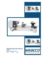
background image


OPERATION MANUAL 

& PART LISTS 


HIGH SPEED PRECISON ENGINE 

LATHE 

Model:  Dynamic 1722S~1790S 

Dynamic 1922S~1990S 
Dynamic 2122S~2190S 


Taiwan: Ya-Gin Machine Tool Manufacturing Inc. 

Ya-Wei Machine Tool Manufacturing Inc. 

No. 101, 506 Lane, Seng-Tso Road 

Seng Karng District, Taichung City, Taiwan 

Tel: 886-4-2520-4120 

Fax: 886-4-2520-4123 


CA: Springwood Industrial, Inc. 

2320 E Valencia, Fullerton, CA 92830  USA 

Tel: 714-871-5558 

Fax: 714-871-5554 


NJ: Klim Industrial, Inc. 

244 N. Randolphville Rd, Piscataway, NJ 08854  USA 

Tel: 732-752-9100 

Fax: 732-752-9101 


Revised: 8/3/23 

ACER 

Summary of Contents for Dynamic 1722S

Page 1: ... Ya Wei Machine Tool Manufacturing Inc No 101 506 Lane Seng Tso Road Seng Karng District Taichung City Taiwan Tel 886 4 2520 4120 Fax 886 4 2520 4123 CA Springwood Industrial Inc 2320 E Valencia Fullerton CA 92830 USA Tel 714 871 5558 Fax 714 871 5554 NJ Klim Industrial Inc 244 N Randolphville Rd Piscataway NJ 08854 USA Tel 732 752 9100 Fax 732 752 9101 Revised 8 3 23 ACER ...

Page 2: ... 11 2 4 Cleaning 11 2 5 Level Adjustment 12 3 ELECTRICAL CIRCUIT CONTROL 3 1 Electrical Wiring 13 3 2 Electrical Equipment 13 3 3 Electrical Cautions 13 3 4 Circuit Diagram 14 4 TESTING OPERATION 4 1 Operation Symbols 19 4 2 Transmission Stop of Spindle 20 4 3 Spindle Speed Selection 20 4 4 Jogging Inching Operation of Spindle 21 4 5 The Importance and Methods of Spindle Balancing Adjustment 22 ...

Page 3: ...eding Stop Operation 24 4 12 Tailstock Operation 25 5 THREADING 5 1 Leadscrew Drive 26 5 2 Threading 26 5 3 Thread Chasing Dial 26 5 4 Thread Feed Chart 28 5 5 Module D P Thread Chart 32 6 LUBRICATION 6 1 Headstock Lubrication 34 6 2 Gear Box Apron Lubrication 34 6 3 Lubrication Chart 34 6 4 Lubrication Location 35 7 MAINTENANCE ADJUSTMENT 7 1 Headstock 36 7 2 Apron Saddle 37 7 3 Gear Box 38 ...

Page 4: ... 7 9 Coolant System Repair 40 8 DELETED LEFT BLANK 9 MECHANICAL DRAWINGS PARTS BREAKDOWN LIST Each Assembly of the Lathe 42 9 1 Headstock Ф58mm or Ф78mm 43 9 2 Gear Box 49 9 3 Apron 55 9 4 Bed and Base 61 9 5 Brake System 64 9 6 Carriage and Crossfeed Assembly 67 9 7 Tailstock Assembly 70 9 8 Steady Rest Assembly 73 9 9 Follow Rest Assembly 75 9 10 Coolant System Assembly 77 ...

Page 5: ...instructions in the manual Any damage of the machine and injury on the operator that is caused by miss operation and disregard of our instruction are not covered under warranty In addition to the instructions listed in our manual there are some matters needing attention as well 1 Do not expose the machine outdoors in order to avoid any damage caused by the weather Besides please keep the machine a...

Page 6: ...6 ...

Page 7: ...7 ...

Page 8: ...8 8 ACER HIGH SPEED PRECISION ENGINE LATHE 1 1 Machine Description Note Color of the lathe depends on OEM specification Figure 1 1 ...

Page 9: ...step feed selection dial 26 Tailstock adjusting gib screw 8 Power source switch Main switch 27 Tailstock body 9 Jog button 28 Tailstock handwheel 10 Coolant supply button 29 Tailstock body Clamping lever 11 Spindle control lever 30 Tailstock spindle locking lever 12 Adjustable trip dog 31 Rack 13 Longitudinal feed hand wheel 32 Compound rest handle 14 Cross slide handle 33 Coolant control ball val...

Page 10: ...ure 2 2 for machine unloading and moving The steps for lifting the lathe are 1 Clamp the bedways with a specially made hanger which consists of a clamp and a wire rope 2 Raise the lathe a little bit with overhead crane and then check to see if the lathe is balanced If not please slide hanger s position left or right to achieve machine s balance 3 When the machine arrives at the location slowly put...

Page 11: ...d achieve a better leveling accuracy Thus reduces the chance of getting vibration 2 4 Cleaning The machine is protected with a special anti rust agent before delivery Before operating the machine please clean all assemblies especially the slideways leadscrew g e a r r a c k s a n d a l l g r o u n d e d s u r f a c e s w i t h s o f t b r u s h c l o t hsoaked with cleaning solvent or kerosene Do ...

Page 12: ... should be placed on the cross slide of the machine Adjust the bolt for longitudinal direction of bed level For transverse direction of bed level tighten the nuts until the a c c u r a c y i s w i t h i n 0 0 4 m m 1 0 0 0 m m T h e n please check the levels again If the deviation is resulted from tightening the nuts it is necessary to make another adjustment See Fig 2 5 Fig 2 5 ...

Page 13: ...rotect motors from current overload 2 The main switch is connected with micro switch 3 The foot brake is connected to a micro switch Stepping on the footbrake is quicker to stop the lathe than turning off the spindle on off switch The spindle will rotate again by lifting the spindle control lever 4 The spindle will run continuously as long as the jog button on the top of the electrical panel is pr...

Page 14: ...24V 5A 5A U1 V1 W1 14 V W LIGHT OP OP QS11 FU1 50A SQ1 SQ2 R2 SPINDLE MOTOR 10HP 7 1 2HP 5HP COOLANT MOTOR 1 8HP SA1 POWER SWITCH SA2 COOLANT SWITCH SB1 E STOP SWITCH SB2 JOGGING SWITCH QS1 DOOR SWITCH SQ1 END COVER SQ2 BRAKE SQ3 FORWARD SQ4 REVERSE 3 4 Circuit Diagram ...

Page 15: ...15 ...

Page 16: ...16 ...

Page 17: ...38 2P 30mm 3A 11 FU4 Fuse 10 38 2P 30mm 3A 12 FU5 Fuse 10 38 1P 13 FU6 Fuse 10 38 1P 14 KM1 Magnetic Contactor CU 27 Coil ac24v 230V 7 5HP TECO 15 KM2 Magnetic Contactor CU 27 Coil ac24v 230V 7 5HP TECO 16 KM3 Magnetic Contactor CU 11 3A1a Coil ac24v 230V 5HP TECO 17 KA1 Magnetic Contactor CU 11 3A1a Coil ac24v 230V 5HP TECO 18 FR1 Overload Relay RHN 80K4 23 32A 26A TECO 19 FR2 Overload Relay RHN ...

Page 18: ...Switch Mj2 1704 250V 15A MOUJEN 28 SQ2 Limit Switch Z 15GW22 B 250V 15A OMRON 29 SQ3 Limit Switch Mj2 1704 250V 15A MOUJEN 30 SQ4 Limit Switch Mj2 1704 250V 15A MOUJEN 31 SQ5 Limit Switch XCKN2102G11 240V 10A TE 32 M1 Spindle Motor 230V 460V 7 5HP 230V 460V 5 595KW 33 M2 Coolant Pump 230V 460V 1 8HP 230V 460V 0 93KW ...

Page 19: ...rease 2 LOW Low speed 12 Electrical control box 3 Forward rotation 13 T H R E A D S Inch threads 4 N Neutral gear 14 m m Metric threads 5 Reverse rotation 15 mm Auto feeding Rate per revolution 6 Feeding 16 Pump 7 T Jog button 17 GREEN Power switch ON 8 Cross feeding 18 R E D Power switch OFF 9 Longitudinal feeding 19 OIL Oil inlet hole 10 Cone clutch ...

Page 20: ...erse rotation always operate the spindle control lever For emergency stop step on the foot brake the spindle control lever should push back to Neutral position after stepping the foot brake Afterward please restart the spindle Turn the coolant supply button 10 of item 1 1 Adjust the coolant control ball valve for the required coolant flow Figure 4 2 4 3 Spindle Speed Selection Spindle speed select...

Page 21: ...indle is still turning Be certain gears are properly engaged before starting Figure 4 3 4 4 Jogging Inching Operation of Spindle For the convenience of spindle speed shifting feeding rate recognition and work piece center lining and adjustment press the jog button 9 located on the right side of the gear box and the spindle will rotate 9 forward The spindle will rotate as longas the jog button is p...

Page 22: ...on the locking nut at the rear side of the spindle The balancing blocks can be properly adjusted according to different condition Please refer to following procedure figure for proper adjustment 2 Firstly set up the spindle speed at 1350 rpm Put the palm on left hand of the headstock cover and press the switch by left hand Then switch on the lathe to make the spindle turn Move the balancing block ...

Page 23: ...selection lever 5 of item 1 1 thread feed shifting lever 6 of item 1 1 and 10 step feed selection dial 7 of item 1 1 as indicated on the threading and feeding table 4 8 Manual Operation First position both the halt nut engage lever 18 and forward reverse shifting lever 4 of item 1 1 to N position to operate the apron handwheel 13 cross slide handle 14 and compound rest handle 32 easily It feeds 20...

Page 24: ...ngaged 5 For longitudinal feeding pull the feed axis selector 4 10 Automatic Feeding Stop Operation The apron is equipped with automatic stop device Release the set screw on the top of the adjustable trip dog 12 move the trip dog to the position and then fix it to the position by tighten the set screw Note that the top section of the adjustable trip dog can be set for the required position in both...

Page 25: ...f apron the other three adjustable trip dogs can pass freely without any function 4 12 Tailstock Operation 1 The tailstock handwheel dial is divided 0 02mm 0 001 per graduation The tailstock moves forward 5mm 0 2 per clockwise revolution of handwheel When rotating counter clockwise the quill will retract and when to the end the dead center will release automatically 2 Push the tailstock quill lock...

Page 26: ...engaged on any number of lines For odd number threads the leadscrew can be engaged on any number Fractional threads 1 2 1 4 etc leadscrew can only be engaged on the same number or line Note When cutting metric threads on a lathe with an Inch leadscrew please be sure the half nut is engaged at all times If not the thread will not repeat 2 Thread indicator dial for Metric leadscrew cutting metric th...

Page 27: ...ision dial But the dial numbers at which the leadscrew may be engaged is on 2 number 1 and 2 Gear teeth Pitch Dial division Half nuts engaged number 11T 2 75 5 5 2 1 13T 3 25 6 5 2 1 1 75 3 5 2 1 2 7 14T 0 5 0 75 1 2 3 4 5 6 7 1 1 5 7 2 3 4 6 15T 1 25 2 5 3 1 2 3 5 2 25 4 5 5 1 2 3 18T 6 75 2 1 2 ...

Page 28: ...8 PAD3 20 PAE4 11 PAF5 4 1 2 PBF2 36 PAD2 19 PAE3 10 PAF4 4 PBF1 LEAD SCREW P 6mm C 0 5 PSF1 1 75 PSE10 3 5 PSD10 6 PUD7 0 75 PSF7 2 PSD1 4 PUD1 7 PUD10 1 PSE1 2 25 PSD2 4 5 PUD2 1 25 PSE4 2 5 PSD4 5 PUD4 1 5 PSE7 3 PSD7 5 5 PUD5 mm mm C T C T 0 05 MF1 0 30 MD4 0 02 MF1 0 15 MD5 0 06 MF2 0 34 MD5 0 03 MF3 0 17 MD7 0 08 MF5 0 37 MD7 0 04 MF7 0 20 MD10 0 10 MF10 0 42 MD10 0 05 ME1 0 24 PD2 0 13 ME2 ...

Page 29: ... PAF6 5 PBF4 38 PAD3 20 PAE4 11 PAF5 4 1 2 PBF2 36 PAD2 19 PAE3 10 PAF4 4 PBF1 LEAD SCREW P 6mm C 0 5 PSF1 1 75 PSE10 3 5 PSD10 6 PUD7 0 75 PSF7 2 PSD1 4 PUD1 7 PUD10 1 PSE1 2 25 PSD2 4 5 PUD2 1 25 PSE4 2 5 PSD4 5 PUD4 1 5 PSE7 3 PSD7 5 5 PUD5 mm mm C T C T 0 05 MF1 0 30 MD4 0 02 MF1 0 15 MD5 0 06 MF2 0 34 MD5 0 03 MF3 0 17 MD7 0 08 MF5 0 37 MD7 0 04 MF7 0 20 MD10 0 10 MF10 0 42 MD10 0 05 ME1 0 24...

Page 30: ...30 0 27 MD2 0 82 PD10 0 12 MD2 ...

Page 31: ... 36 PAD2 19 PAE3 10 PAF4 4 PBF1 LEAD SCREW P 4TPI C 0 5 PSF1 1 75 PSE10 3 5 PSD10 6 PUD7 0 75 PSF7 2 PSD1 4 PUD1 7 PUD10 1 PSE1 2 25 PSD2 4 5 PUD2 1 25 PSE4 2 5 PSD4 5 PUD4 1 5 PSE7 3 PSD7 5 5 PUD5 in in C T C T 0 002 MF1 0 011 MD4 0 0008 MF1 0 0046 MD5 0 0025 MF2 0 012 MD5 0 001 MF3 0 005 MD7 0 003 MF5 0 013 MD7 0 0012 MF7 0 006 MD10 0 004 MF10 0 016 MD10 0 0017 ME1 0 007 PD2 0 005 ME2 0 017 PD1 ...

Page 32: ... 20 PAE4 11 PAF5 4 1 2 PBF2 36 PAD2 19 PAE3 10 PAF4 4 PBF1 LEAD SCREW 4TPI C 0 5 PSF1 1 75 PSE10 3 5 PSD10 6 PUD7 0 75 PSF7 2 PSD1 4 PUD1 7 PUD10 1 PSE1 2 25 PSD2 4 5 PUD2 1 25 PSE4 2 5 PSD4 5 PUD4 1 5 PSE7 3 PSD7 5 5 PUD5 mm mm C T C T 0 05 MF1 0 29 MD4 0 02 MF1 0 14 MD5 0 06 MF2 0 32 MD5 0 03 MF3 0 16 MD7 0 08 MF5 0 35 MD7 0 04 MF7 0 18 MD10 0 10 MF10 0 40 MD10 0 05 ME1 0 2 PD1 0 13 ME2 0 45 PD1...

Page 33: ... 27 PAE9 14 PAF10 8 PAF1 48 PAD7 26 PAE8 13 1 2 PAF9 7 PBF10 46 PAD6 24 PAE7 13 PAF8 6 PBF7 44 PAD5 23 PAE6 12 PAF7 5 1 2 PBF5 40 PAD4 22 PAE5 11 1 2 PAF6 5 PBF4 38 PAD3 20 PAE4 11 PAF5 4 1 2 PBF2 36 PAD2 19 PAE3 10 PAF4 4 PBF1 LEAD SCREW P 6mm 50T C 0 5 PSF1 1 75 PSE10 3 5 PSD10 6 PUD7 0 75 PSF7 2 PSD1 4 PUD1 7 PUD10 1 PSE1 2 25 PSD2 4 5 PUD2 1 25 PSE4 2 5 PSD4 5 PUD4 1 5 PSE7 3 PSD7 5 5 PUD5 ...

Page 34: ... PAF10 8 PAF1 48 PAD7 26 PAE8 13 1 2 PAF9 7 PBF10 46 PAD6 24 PAE7 13 PAF8 6 PBF7 44 PAD5 23 PAE6 12 PAF7 5 1 2 PBF5 40 PAD4 22 PAE5 11 1 2 PAF6 5 PBF4 38 PAD3 20 PAE4 11 PAF5 4 1 2 PBF2 36 PAD2 19 PAE3 10 PAF4 4 PBF1 LEAD SCREW 4TPI 31T C 0 5 PSF1 1 75 PSE10 3 5 PSD10 6 PUD7 0 75 PSF7 2 PSD1 4 PUD1 7 PUD10 1 PSE1 2 25 PSD2 4 5 PUD2 1 25 PSE4 2 5 PSD4 5 PUD4 1 5 PSE7 3 PSD7 5 5 PUD5 ...

Page 35: ...hs 2 Apron is also reservoir oil bath type Please add more oil as soon as the oil level is lower than the center line of the oil sight glass 6 3 Lubrication Charts No Location Methods Lubricant No Quantity Oil time Replacement time 1 Headstock Loosen the oil input cap on the left top side ofthe headstock cover Shell Tellus 32 Centerline Once month per One month at the beginning thereafter every si...

Page 36: ...36 6 4 Lubrication Location A Oil input cap B Oil drain hole ...

Page 37: ...n blow air to the small hole which is on the top of the front bearing by air gun several times And rotate the spindle at the same time to clean up the blocked returning oil line 3 Spindle bearing adjustment The front and middle bearings of the spindle is precision taper roller type It is specified to require the bearings to have suitable preload for maintaining the high accuracy and the best rotat...

Page 38: ...on 5 To clean up and repair the manual pump being blocked or when it has small oil flow If no oil oozes out after pushing the manual pump several times the pump is blocked Take off the fourset screws of the pump body and loosen the plug lever to dismantle the cover nut Use air gun to clean up the inside of the blocked pump If the oil flow is too small the O ring must have been worn out please repl...

Page 39: ... right and left side which lock the tailstock body and base together Determine the direction and amount of the misalignment for adjustment by positioning a test bar between two dead centers Unscrew the rear gib screw say one half turn Then screw in front side s gib screw and tighten the other until the required setting or correct alignment is achieved Carefully retighten the rear and front gib scr...

Page 40: ...elt tension is achieved 3 After adjustment please be sure to tighten the adjusting nut securely A Fig 7 5 7 6 Brake Belt Adjustment If the brake belt is worn out and cause the brake band to be loosen It is time to adjust the nut H of the brake band Remove the side rear cover loosen the nuts on the top of brake band and tighten the nuts on the bottom to the appropriate height Then tighten the nuts ...

Page 41: ...t properly open the plastic cover of the leadscrew bracket and loosen nut A Then tighten the left side nut B until there is no backlash For testing press down the half nut by hand turn the apron handwheel forward and reverse to feel the connecting section of the gear box and leadscrew until no backlash has been sensed Afterwards put back the nut A to the leadscrew bracket A B Figure 7 8 7 9 Coolan...

Page 42: ...ical Drawings Parts Breakdown List Note When ordering parts please be prepared with 1 Machine model serial number 2 Item number 3 Part number and description 4 Year of Production 5 Voltage horsepower 6 Quantity ...

Page 43: ...43 ...

Page 44: ...44 8 1 Headstock ...

Page 45: ...05B 20200706B 20200706B 12 Gear g 1 1120200803 1120200803 1120200803 13 Square key 8x7x55L 1 14 Ball bearing 6206 2 91301021 91301021 91301021 15 Collar 1 3001015 001 3001015 001 3001015 001 17 Housing 1 1120206903 1120206903 1120206903 18 Oil seal TC30x50x8 1 19 Hexagon socket screw M6xP1x35L 4 20 Pulley 1 3001020 3001020 3001020 21 Square key 8x7x45L 3 22 Hexagon socket screw M8xP1 25x25L 1 23 S...

Page 46: ...00405 1320200405 44 Square key 8x7x35L 1 45 Snap ring S48 2 46 Snap ring S34 1 47 Gear h 1 1120201604 1120201604 1120201604 48 Gear j 1 320200503B 320200503B 320200503B 49 Square key 8x7x25L 1 50 Ball bearing 6205 2 91301020 91301020 91301020 51 Cover 1 1120203108 1120203108 1120203108 52 Spindle D1 8 1 122020090 122020090 122020090 53 Taper roller bearing 32922 1 91302028 91302028 91302028 54 Cov...

Page 47: ...r 1 1120207606 1120207606 1120207606 74 Hexagon socket screw M6xP1 0x12L 13 75 Gear shaft C 1 1120202101 1120202101 1120202101 76 Ball bearing 6204 5 91301018 91301018 91301018 79 Gear 1 1120202209 1120202209 1120202209 80 Gear 1 122020160 122020160 122020160 81 Square key 6x6x65L 1 82 Cover 1 1120203902 1120203902 1120203902 83 Shaft D 1 3001083 001 3001083 001 3001083 001 84 Gear 1 1120202405 11...

Page 48: ... 110 Hub 2 112020521 112020521 112020521 110 1 Hub 1 112020531 112020531 112020531 111 Square key 5x5x15L 2 112 Ball steel φ5 16 3 113 Spring D8xd0 8x25L 3 114 Lever 3 1120207302 1120207302 1120207302 115 Knob 3 1120207400 1120207400 1120207400 116 Shaft 1 1220200501 1220200501 1220200501 117 Shifting lever 1 1120205504 1120205504 1120205504 118 Shifting lever 1 1120208309 1120208309 1120208309 11...

Page 49: ...rew M6xP1 0x14L 10 130 Lenz oil φ29 1 92552001 92552001 92552001 131 Spring pin φ5x32L 9 Spring pin φ5x26L 2 132 Snap ring S12 3 133 Snap ring S10 2 134 Set screw M10x1 5x20L 2 135 Hexagon socket screw M10xP1 5x95L 2 136 Hexagon socket screw M6xP1 0x40L 4 137 Square key 6x6x70L 1 ...

Page 50: ...50 8 2 Gearbox ...

Page 51: ...06 13 Collar 1 1210301304 1210301304 1210301304 14 Set screw M8x12 2 15 Ring O P18 2 16 Shaft A 1 1210301402 1210301402 1210301402 17 Pin taper 4x38 3 92010438 92010438 92010438 18 Pin taper 6x38 2 1210702301 1210702301 1210702301 19 Collar linkage 2 1210301500 1210301500 1210301500 20 Hexagon socket screw M6xP1 0x16L 6 21 Cap right 1 1210301608 1210301608 1210301608 22 Seal oil 1 23 Bearing ball ...

Page 52: ...1 1210303308 1210303308 1210303308 50 Gear D shaft 24T 1 1210303406 1210303406 1210303406 51 Gear D shaft 27T 1 1210303504 1210303504 1210303504 52 Gear D shaft 24T 1 1210303602 1210303602 1210303602 53 Gear D shaft 26T 1 1210303700 1210303700 1210303700 54 Gear D shaft 36T 1 1210303808 1210303808 1210303808 55 Gear D shaft 27T 1 1210303906 1210303906 1210303906 56 Gear D shaft 28T 1 1210304001 12...

Page 53: ...exagon socket screw M8xP1 25x16L 1 81 Bolt lock end cover 1 1122100208 1122100208 1122100208 82 Stud 1 1121601108 1121601108 1121601108 83 Washer 1 2 1 1121602301 1121602301 1121602301 84 Nut W1 2 1 85 Nut lock stud 1 1121601706 1121601706 1121601706 86 Quadrat 1 1121601000 1121601000 1121601000 87 Stud gear 1 1121601206 1121601206 1121601206 88 Snap ring R35 1 89 Geat quadrat 71T in 1 1121600209 ...

Page 54: ...101607 104 Rod feed 1 1210700307 1210700307 1210700307 105 Set screw M6xP1 0x20L 2 106 Pin taper 6x100L 1 1210700601 1210700601 1210700601 107 Hexagon socket screw M8xP1 25x80L 1 108 Bushing spindle starting rod 1 1210700905 1210700905 1210700905 109 Rod spindle starting switch 5 feet 1 1210700405 1210700405 1210700405 6 feet 1 1220700408 1220700408 1220700408 8 feet 1 1230700401 1230700401 123070...

Page 55: ... S10 3 136 Pin spring 5x25 3 137 Shaft shifter 3 1210306103 1210306103 1210306103 138 Ring O P12 3 139 Detent Plate 1 121030621 121030621 121030621 139 1 Detent Plate 1 1210306309 1210306309 1210306309 139 2 Detent Plate 1 121030641 121030641 121030641 140 Ball steel 1 4 3 141 Spring 5x26 3 142 Hub 3 1210306505 1210306505 1210306505 143 Lever 3 1210306701 1210306701 1210306701 144 Snap ring S15 1 ...

Page 56: ...56 3 Apron ...

Page 57: ...51 121090051 mm 1 121090061 121090061 121090061 7 Holder half nut right hand 1 1210900405 1210900405 1210900405 left hand 1 1210900307 1210900307 1210900307 8 Hexagon socket screw M6xP1 0x16L 1 9 Pin sliding 2 1210902507 1210902507 1210902507 10 Shaft haft nut right hand 1 1210900807 1210900807 1210900807 left hand 1 1210900709 1210900709 1210900709 11 Ring O P26 2 12 Set screw M8xP1 25x20L 2 1210...

Page 58: ...90601 34 Seal oil 32x42x10 1 35 Bushing 2 1210901804 1210901804 1210901804 36 Sleeve feed rod 1 1210901902 1210901902 1210901902 37 Key sqaure 6x6x42L 1 38 Key sqaure 6x6x12L 1 39 Gear 1 1210903200 1210903200 1210903200 40 Seat worm 1 1210903308 1210903308 1210903308 41 Shaft worm 1 1210903406 1210903406 1210903406 42 Bearing thrust 2904 2 91311005 91311005 91311005 43 Worm gear 1 1210902007 12109...

Page 59: ...65 Bearing ball 6005V 1 91301012 91301012 91301012 66 Worm wheel 1 1210902105 1210902105 1210902105 67 Wheel friction 1 1210902203 1210902203 1210902203 68 Key square 7x7x12L 1 69 Shaft worm wheel 1 1210904001 1210904001 1210904001 70 Pin 1 1210904109 1210904109 1210904109 71 Spring compressing 1 1210905302 1210905302 1210905302 72 Washer 1 1210904207 1210904207 1210904207 73 Set screw 1 74 Bearti...

Page 60: ...ll 6004V 1 91301008 91301008 91301008 95 1 Bearing ball 6005Z 1 91301007 91301007 91301007 96 Seat 1210905204 1210905204 1210905204 97 Hexagon socket screw M6xP1 0x30L 4 99 Washer 1210701608 1210701608 1210701608 100 Washer wave type 1 101 Dial rack 1 1220900202 1220900202 1220900202 102 Handwheel 1 112210171 112210171 112210171 103 Handle 1 1121102002 1121102002 1121102002 104 Washer lock 1 11221...

Page 61: ... 112 Nut M10xP1 5 1 113 Snap ring S30 1 114 Seat switch 1 1210701706 1210701706 1210701706 115 Key square 6x8x25L 1 116 Hexagon socket screw M8xP1 25x16L 2 117 Bracket 1 1210701804 1210701804 1210701804 118 Screw lock 2 1210701902 1210701902 1210701902 119 Screw hexa socket headless cap 1 1210702007 1210702007 1210702007 120 Seat lever 1 1210702105 1210702105 1210702105 121 Set screw M8xP1 25x8L 2...

Page 62: ...62 8 4 Bed and Base ...

Page 63: ...700502 1240700502 1240700502 7 Bed 5 feet 1 1210100101 1210100101 1210100101 6 feet 1 1220100104 1220100104 1220100104 8 feet 1 1230100107 1230100107 1230100107 10 feet 1 1240100100 1240100100 1240100100 8 Pin taper 6x36 2 9 Hexagon socket screw M16xP2 0x45L 4 10 Supporter shaft 1 1122102104 1122102104 1122102104 11 Set screw M6xP1 0x10L 2 12 Collar 1 1122102202 1122102202 1122102202 13 Shoe brass...

Page 64: ...102702 27 Bolt lock 1 1122100208 1122100208 1122100208 28 Cover motor seat 2 1122100806 1122100806 1122100806 29 Bolt set machine 6 112210281 112210281 112210281 30 Nut lock 6 1122102800 1122102800 1122102800 31 Block leveling 6 1003501809 1003501809 1003501809 32 Bolt hexa head W1 4 x25 2 33 Washer W5 8 2 34 Seat coolant pump 1 121010051 121010051 121010051 35 Cover coolant motor seat 1 100500040...

Page 65: ...65 8 5 Break System ...

Page 66: ...ocket screw M10xP1 5x20L 3 12 Bracket motor seat 1 1210100709 1210100709 1210100709 13 Bracket pedal 2 1210400900 1210400900 1210400900 15 Pedal brake 5 feet 1 1210400508 1210400508 1210400508 6 feet 1 1220400109 1220400109 1220400109 8 feet 1 1230400102 1230400102 1230400102 10 feet 1 1240400105 1240400105 1240400105 16 Shaft pedal bracket 5 feet 1 1210100105 1210100105 1210100105 6 feet 1 122010...

Page 67: ...3 25 Belt pulley 5HP 60HZ 1 3005025 3005025 3005025 7 5HP 10HP 60HZ 1 3005025 004 3005025 004 3005025 004 26 Set screw M8xP1 25x8L 1 27 Key 8x7 5x40 5HP 1 10x8x65 7 5HP 1 10HP 1 12x8x80 15HP 1 28 Motor 5HP 220 440 60 1 81000103 81000103 81000103 7 5HP 220 440 60 1 81000205 81000205 81000205 29 Bolt hexa head M10x30L 4 ...

Page 68: ...68 8 6 Carriage and Crossfeed ...

Page 69: ...800403 1220800403 1220800403 17 Hexagon socket screw M8xP1 25x20L 2 18 Set screw M8xP1 25x20L 5 19 Nut M8xP1 25 4 20 Case wiper front 1 1122100404 1122100404 1122100404 21 Wiper front 1 1122100100 1122100100 1122100100 22 Pin taper 6 75L 2 1210700503 1210700503 1210700503 23 Hexagon socket screw M10xP1 5x70L 4 24 Gib left front 1 1120801202 1120801202 1120801202 25 Set screw M6xP1 0x20L 3 26 Clamp...

Page 70: ...70 35 Washer wave type 6210 2 36 Set screw M6xP1 0x10L 1 ...

Page 71: ...20803402 1120803402 44 Plug oil inlet 1 1121103405 1121103405 1121103405 45 Lever 1 1120801506 1120801506 1120801506 46 Screw carriage clamp 1 1120800607 1120800607 1120800607 47 Case wiper 1 48 Wiper 1 1222100102 1222100102 1222100102 49 Screw adjusting 1 50 Gib 1 1220800305 1220800305 1220800305 51 Bolt 1 1120800509 1120800509 1120800509 52 Cover cross sliding 1 1430800802 1430800802 1430800802 ...

Page 72: ...72 70 Tool post square export 1 1003512802 1003512606 local 1 1003512704 1003512508 ...

Page 73: ...73 8 7 Tailstock ...

Page 74: ... 1221100108 16 Spindle tang slot 1 1121101309 122110101 122110101 17 Cap spindle 1 18 Hexagon socket screw M8xP1 25x10L 3 19 Screw spindle feed in 1 122110031 122110031 122110031 mm 1 122110041 122110041 122110041 20 Key square 6x6x25 1 21 Bearing thrust 51204 2 91303005 91303005 91303005 22 Cap body end 1 1121101407 1221101105 1221101105 23 Screw hexa Socket head cap 96xP1 0x25L 4 24 Dial feed in...

Page 75: ...75 38 Case 1 1122100502 1122100502 1122100502 39 Wiper 1 1122100100 1122100100 1122100100 ...

Page 76: ... Model 17 430 Part No Model 19 480 Part No Model 21 530 Part No 40 Bottom tailstock 1 122110141 122110021 9307040 41 Bolt clamp 1 9307041 1 9307041 2 9307041 3 42 Block adjusting 1 1221101301 1221101301 1221101301 43 Screw hexa socket M10xP1 5x80L 2 ...

Page 77: ...77 8 8 Steady Rest ...

Page 78: ...ller type 1 1003519301 1003501201 9 Bronze tip type 1 1003501309 3008001 008 9 Roller type 1 1003501407 3008001 007 2 Plug lead screw 3 3 Cap 6x52L 3 4 Pin 3 5 Lead screw 3 6 Nut lead screw 3 7 Screw fixed 3 8 Jaw 3 9 Pin fixed 3 10 Pin 9x25L 2 11 Screw 1 12 Plug 1 13 Nut W5 8 1 14 Washer 1 15 Block clamp 1 3008015 3008015 3008015 16 Bolt 1 1003500400 1003500400 1003500400 ...

Page 79: ...79 8 9 Follow Rest ...

Page 80: ... No 1 Body follow rest Bronze tip type 1 1003519409 1003503107 3008021 003 Roller type 1 100352700 100352710 3008021 004 2 Nut lead screw 2 3 Lead screw 2 4 Collar 2 5 Pin 4x25L 2 6 Plug lead screw 2 7 Screw hexa Socket headless cap M8xP1 25x10L 4 8 Shoe 2 9 Screw hexa Socket head cap M10xP1 5x30L 2 10 Washer 2 ...

Page 81: ...81 8 10 Coolant System ...

Page 82: ...92605002 92605002 92605002 8 feet 1 92605003 92605003 92605003 10 feet 1 92605001 92605001 92605001 7 Elbow 1 8 Pump body 220V 380V 1 92111801 92111801 92111801 220V 440V 1 92111802 92111802 92111802 415V 1 92111804 92111804 92111804 600V 1 92111806 92111806 92111806 110V 1 92111807 92111807 92111807 9 Bolt hex Head M6xP1 0x12L 2 10 Supporter lock pipe 1 11 Screw hexa Socket head cap M6xP1 10x20L ...

Reviews: