background image


Acer AT4250B LCD TV   

                  Service Guide 


PRINTED IN CHINA 

Service guide files and updates are available on 
the ACER/CSD web. For more information, 
please refer to http://csd.acer.com.tw 

Summary of Contents for AT4250B series

Page 1: ...Acer AT4250B LCD TV Service Guide PRINTED IN CHINA Service guide files and updates are available on the ACER CSD web For more information please refer to http csd acer com tw ...

Page 2: ...Revision History Please refer to the table below for the updates of LCD TV AT4250B service guide Date Chapter Updates 2007 10 29 Chapter 1 4 1st edition II ...

Page 3: ...cation may be reproduced transmitted transcribed stored in a retrieval system or translated into any language or computer language in any form or by any means electronic mechanical magnetic optical chemical manual or otherwise without the prior written permission of Acer Incorporated III ...

Page 4: ...cer Incorporated software described in this manual is sold or licensed as is Should the programs prove defective following their purchase the buyer and not Acer Incorporated its distributor or its dealer assumes the entire cost of all necessary servicing repair and any incidental or consequential damages resulting from any defect in the software Acer is a registered trademark of Acer Incorporated ...

Page 5: ...its and pieces of additional information related to the current topic WARNING Alerts you to any damage that might result from doing or not doing specific actions CAUTION Gives precautionary measures to avoid possible hardware or software problems IMPORTANT Reminds you to do specific actions relevant to the accomplishment of procedures V ...

Page 6: ... NOT be covered in this generic service guide In such cases please contact your regional offices or the responsible personnel channel to provide you with further technical details 2 Please note WHEN ORDERING FRU PARTS you should check the most up to date information available on your regional web or channel For whatever reason if a part number change is made it will not be noted in the printed Ser...

Page 7: ... B and Audio 21 pin Euro SCART RGB for Video S Video R G B and Audio RCA jack YUV and CVBS for YPbPr YCbCr Video and Audio 15 pin D Sub for VGA 19 pin D Sub for HDMI 2 DIN45325 IEC169 2 Terminal for TV CATV input 3 5 mm Earphone jack for Audio Line input Broadcasting TV signal PAL color system Receivable only Full frequency range From channel 1 48 25 MHz to channel 57 863 25 MHz TV system support ...

Page 8: ...m PIP POP Mechanical VESA mounting holes Compatibility Multi Sound system NICAM FM Stereo A2 Power Source Input voltage 90 264 V 47 63 Hz Input current 2 7A max at 100Vac Power consumption 291Watts Stand by 5 Watts Max Remote controllers Multi function remote controller Speaker Internal speaker 10 W x 2 stereo volume adjustable Others On screen display adjustment function ISP In System Programming...

Page 9: ...System Block Wiring Diagram I O Board CVBS RCA YPbPr RCA Tuner SPEAKER L IR power button Bd Key Earphone Board SPEAKER R INVERTER PANEL Board POWER MAIN Board Audio R L 3 Chapter1 ...

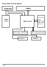
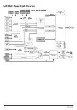
Page 10: ...LCD Main Board Block Diagram Chapter1 4 ...

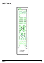
Page 11: ...Remote Control 5 Chapter1 ...

Page 12: ...e subscreen size 25 37 5 50 When POP mode Size mode Change POP mode 1 5 1 12 Position Change position of subscren in PIP mode left up right up right down left down Active Deactive channel scan in POP mode Activate Active main or sub window audio in PIP PBP mode Swap Swap primary and sub screen in toggle Four way direction key up Navigate up in the OSD or next sub page in teletext mode down Navigat...

Page 13: ...e down Volume down Teletext Teletext on off Index Go to index page usually page 100 Subpage Enter Leave subpage mode Reveal Display Hidden Information Hold Temporarily holds the current teletext page Mix Overlay the telext page on the TV picture Zoom page toggle 1X 2X Size Page select by Up arrow and Down arrow Teletext Turn teletext mode on off Subtitle Show subtitle on the screen R Colour button...

Page 14: ...g TV system Destination PAL SECAM Color System CCIR B G D K I and L L Sound System Sound 1 and Sound 2 Stereo System NICAM and FM Stereo A2 Channel System Full frequency range from channel E2 48 25 MHz to channel E69 855 25 MHz Terminal Analog RF 75Ω DIN45325 IEC169 2 Type AV 1 Euro SCART RGB for Video S Video RGB and Audio AV 2 Euro SCART RGB for Video S Video RGB and Audio AV 3 RCA for YPbPr or ...

Page 15: ...600 37 879 60 VESA 8 800 600 48 077 72 VESA 9 800 600 46 875 75 VESA 10 800 600 53 7 85 VESA 11 1024 768 48 363 60 VESA 12 1024 768 56 476 70 VESA 13 1024 768 60 023 75 VESA 14 1360 768 47 7 60 VESA This LCD TV would detect the used mode automatically Preset Mode for HDMI Input 16 factory pre set modes for DVI inputs are saved during the manufacturing process Preset mode Pixel Format Hor Freq kHz ...

Page 16: ...how NO VGA CONNECTION Transition from any power saving state to another can be instantaneous The recovery from Off state requires no manual power on Mode Hsync Vsync Video Power Indication Recovery time Power On On On Active 161W Green Stand by Off On Off 5W Red 5s Suspend On Off Off 5W Red 5s Off state Off Off Off 5W Red 5s Power off 5W Dark Turn on 5s Sync on means normal operation Sync off mean...

Page 17: ... and brightness to max and color temperature of Standard is selected Typical value would be 400 Cd m2 Power Supply Electrical Specifications The power supply for this product is an internal converter with a non replaceable fuse internally This converter shall be well designed to meet CE mark requirement Input Voltage and Frequency Range The operating range of line voltage shall be AC 100 volts to ...

Page 18: ...3 amps or lower when power off Current will stay below 100 m amps while power on then ramp up to full power about 2 3 amps at AC 120 volts within 5 seconds when power up signal is triggered For the shut down sequence the current will stay at full power for about 150 m seconds or less then ramp down to 100 m amps within 1 second Power on LED Location and Type Power on indicator shall be easily visi...

Page 19: ...rity White Point Mis convergence Luminance measurements and White uniformity measurement Operating temperature 0 C to 35 C Operating humidity 10 to 90 non condensing Storage and Shipping Storage temperature 20 C to 60 C Shipping temperature 20 C to 60 C Storage humidity 10 to 90 non condensing Shipping humidity 10 to 90 non condensing 13 Chapter1 ...

Page 20: ...ition as below 1 Random vibration 10 500 Hz 1 47G RMS B The unit under test shall be run for a duration of 30 minute in each of following orientations a Top and bottom side z axis b Left and right side x axis c Front and rear side y axis The unit shall suffer no visible cosmetic damage and should operate no degradation indisplay quality after test Additionally prior to production and prior to impl...

Page 21: ...ith the VESA DDC standard In addition the display can respond to a request for EDID to be transmitted using DDC2 level B commands If a DDC2 capable host is detected by the display the display shall switch to DDC2 communication The EDID shall contain the manufacture name code QCI product code date of manufacture and serial number For complete EDID data structure please refer to VESA Extended Displa...

Page 22: ...0 6 30 30 30 30 0A 20 20 20 20 20 20 20 0 0 0 FC 7 0 61 63 65 72 20 41 54 33 32 30 32 0A 20 0 5A For HDMI input 1 Product Revision 0 1 2 3 4 5 6 7 8 9 A B C D E F 0 0 FF FF FF FF FF FF 0 4 72 4 27 1 1 1 1 1 0 0F 1 3 80 3C 22 78 2A 3B 90 A7 54 46 98 24 2 10 49 4B 20 0 0 1 1 1 1 1 1 1 1 1 1 3 1 1 1 1 1 1 1 1D 80 18 71 1C 16 20 58 2C 4 25 0 C4 8E 21 0 0 9E 0 0 0 FD 0 32 55 1E 5 50 0B 0 0A 20 20 20 20...

Page 23: ...e module during operation or just after powered off you must take proper precautions against electric shock and must not touch the drive circuit portion and metallic part of module within 10 minutes The capacitors in the drive circuit portion remain temporarily charged even after the unit is powered off If the residual voltage is strong enough it could result in electric shock Thus we strongly sug...

Page 24: ...1 Release 6pcs screws from base and take off it 2 Release 10pcs screws from rear cover 3 Release 10pcs screws from rear cover 4 Release 6pcs screws from stand brackets Chapter2 18 ...

Page 25: ...I and IO joint 6 Release 6pcs screws from PCB shielding 7 Release 8pcs screws from PCB shielding 8 Release 8pcs screws from left and right speakers 9 Release 2pcs screws from IR B 10 Release 3pcs screws from Keypad B 2 3 19 Chapter2 ...

Page 26: ...11 Release 9pcs screws from Boards 12 Release 7pcs screws from boards 13 Release 4pcs screws from Power B 14 Release 7pcs screws from panel brackets Chapter2 20 ...

Page 27: ...pcs screws from chassis and LVDS cable 16 Rlease 11pcs screws from bezel and brackets 17 Release 4pcs screws from top panel brackets 18 Release 4pcs screws from buttom panel brackets then take off them 21 Chapter2 ...

Page 28: ...tom Verify the symptoms by attempting to re create the failure by running the diagnostic test or by repeating the same operation 3 Disassemble and assemble the unit without any power sources 4 If any problem occurs you can perform visual inspection before you follow this chapter s instructions You can check the following ٛ Power cords are properly connected and secured ٛ There are no obvious short...

Page 29: ... Replace Inverter Board Swap test fixture LCD panel No Picture Replace LCD panel No Replace Main Board Replace Power Board To switch on Power LED to show red Power button LED color with red Yes No Upload F W Swap test fixture Power Board LED to bright Yes LED to show green Yes No LCD panel with backlight Yes LCD wth backlght Yes Swap test fixture Main board LED to show green No Yes Replace On Off ...

Page 30: ...VDS cable is well Poor picture Swap the test fixture Main Board Replace LVDS cable NTF END No Yes No Poor picture Replace Main Board No Press Power On Off Button to LED color show green Picture right Upload F W POOR PICTURE QUALITY Poor picture Yes Replace LCD panel Yes 24 Capter3 ...

Page 31: ...de and RF cable Swap test fixture Tuner Board No broken Replace Tuner Board NTF END No No Press Power On Off Button to LED color show green No TV signal Upload F W NO TV SIGNAL ISSUE No signal Yes Replace Main Board Yes Chapter3 25 ...

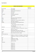
Page 32: ...26 Capter3 ...
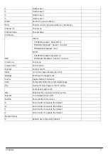
Page 33: ...ver reasons a part number change is made it will NOT be noted on the service guide For Acer authorized service providers your Acer office may have a different part number code from those given in the FRU list of this printed service guide You MUST use the local FRU list provided by your regional Acer office to order FRU parts for repair and service of customer machines Note To scrap or to return t...

Page 34: ...HV4A GP DD0HX4AB003 50 M34V7 005 CABLE ASSY CABLE ASSY HV9 GND 1P 1P 2A GP DD0HV9TH108 50 M26V7 004 CABLE ASSY CABLE ASSY MB POW LG 170MM 10 14P HH7 GP DD0HH7PB104 Case Cover Bracket Assembly LCD BEZEL ASSY HV4E LCD BEZEL ASSY FHD GP 36HV4LBTN12 60 M3507 001 BACK COVER AH4T BACK COVER ASSY GP 47AH4BC0I06 60 M34V7 002 STAND ASSY HV4 STAND ASSY GP 27HV4SATN07 60 M34V7 003 STAND BASE STAND BASE HV4 E...

Page 35: ...HV4004018 47 M3507 001 SCREW SCREW SCREW M4 0 6 0 B NI GP MM40060BBJ5 86 M08V7 005 SCREW SCREW M3 6 B BNI GP MM30060BJ25 86 M08V7 003 SCREW SCREW T3 12 P BNI WASHER GP MS30120PCT3 86 M3507 004 SCREW SCREW M4 6 P NI GP MM40060PCE2 86 M01V7 002 SCREW SCREW M4 22 B BNI WASHER SPRING GP MM40220BK82 86 M34V7 002 SCREW SCREW T4 12 B BNI GP ME40120BJ24 86 M25V7 003 SCREW SCREW T3 8 B BNI GP MT30080BJ20 8...

Page 36: ... 4 14 CLAMP CMO D HX4 FBHX4005 REV3A GP FBHX4005010 47 M3507 002 1 15 STAND BKT HX4 FAHX4008 REV3A GP FAHX4008018 33 M34V7 001 2 16 1 17 2 18 2 19 1 20 GASKET 385X15X14 HV4E GBHV4004 3A GP GBHV4004018 47 M3507 001 2 21 CMO GASKET LVDS HX4 GBHX4P01 3A GP GBHX4P01017 1 22 CMO GASKET UP HX4 GBHX4P02 3A GP GBHX4P02013 3 23 CMO GASKET DOWN HX4 GBHX4P03 3A GP GBHX4P03010 1 24 CMO GASKET POWER HX4 GBHX4P...

Page 37: ...37 SCREW M4 22 B BNI WASHER SPRING GP MM40220BK82 86 M34V7 002 10 38 SCREW T3 12 P BNI WASHER GP MS30120PCT3 86 M3507 004 8 39 SCREW T3 8 B BNI GP MT30080BJ20 86 M08V7 007 8 Chapter4 31 ...

Page 38: ......

Reviews: