ARMC/3P
Quick Installation and Setup Guide
For more detailed instructions, please consult the User Manual found on the enclosed CD-ROM. Rev. A March 2007
Connecting Power using
External Power Adaptor
An external power supply could be
connected to the ARMC/3P in order
to use the remote power on/off fea-
tures provided by the ARMC/3P.
To allow the ARMC/3P to operate
independently from the server sys-
tem it is possible to connect the
card to an external power supply.
From the technical point of view
any power supply can be used as
long as the following specifications
are met:
Voltage:
5V
Current:
>= 1A
Pinning:
Plus on inner connector
Dimension:
2.1 mm diameter
We recommend a 5V /1A power
supply. Contact your local sales
representative for a Acer approved
power supply.
Important:
Any standard power
supply compliant with the require-
ments stated above may be used.
Nevertheless, any warranty from
Acer voids if non-Acer power sup-
plies are used in conjunction with
the ARMC/3P. Check for the Acer
approval label on the external
power supply in order to preserve
your manufacturer's warranty.
Connecting Power and Reset
Cables
The ARMC/3P offers the possibility
to remotely control both the power
and the reset functions of the host
system. In order to support it, there
is additional cabling necessary. The
preferred way for this cabling are the
interfaces offered by IPMI. However,
if your host does not support IPMI
you may use other possibilities.
(a) IPMI over IPMB
This connection is used to power on or off the
system, or to perform a hard reset. You must
have a motherboard that supports IPMI 1.5 or
higher and has a 3 or 4 pin IPMB connector as
shown in the Figure below.
1.
Connect the 5 pin connector of the IPMB
cable with the 1x5 pin IPMB connector on the
ARMC/3P as shown in the schema with all con-
nectors of the ARMC/3P. The red wire of the
IPMB cable has to be connected to pin 1 at the
ARMC/3P.
2.
Connect the ending of the cable with one of
the IPMB connectors (3 or 4 pin connector) on
the motherboard.
3.
Set the IPMI settings to IPMI over IPMB.
4.
Make sure that the IPMI function is enabled
on the host system.
(b) ATX Power Reset
If there are separate pins for the reset and power
switch connectors on the motherboard, refer to
the motherboard manual to find the right con-
nectors for the front panel reset/power switch
buttons:
1.
Disconnect the reset cable from the mother-
board and connect it to the connector RST1 of
the ARMC/3P.
2.
Connect the connector RST2 on the
ARMC/3P using the enclosed reset cable (two
wires, black/red) with the reset connector on the
motherboard.
3.
Disconnect the power switch cable from the
motherboard and connect it to the connector
PWR1 on the ARMC/3P.
4.
Connect the connector PWR2 on the
ARMC/3P using the enclosed power switch
cable (two wires, black/red) with the power
switch on the motherboard.
In case your motherboard does not have single
pins for reset and power switch, you may use
one of the front panel adapters which are
offered.
Connecting the VGA-USB System
Cable and the Videosplitter
1.
Use the video cable to connect the VGA out-
put of the host with the VGA input on the
ARMC/3P. In case a local video display is
required, please use the videosplitter as shown
below. Make sure that the connector with
screws is mounted to the computer VGA out.
2.
Connect the USB plug with one of the host's
own USB connectors.
3.
Connect the Ethernet jack to a hub or switch
using an UTP 5 cable if required.
Connecting Ethernet
The bracket of the ARMC/3P provides a RJ45
connector for Ethernet. The connector is used
either for a 100 Mbps 100BASE-TX connection
or for a 10 Mpbs 10BASE-T connection. The
adapter can sense the connection speed and
will adjust to the appropriate operation automat-
ically.
(a) 10 Mpbs Connection
For 10BASE-T ethernet networks the Fats
Ethernet adapter uses category 3, 4, or 5 UTP
cable. To establish a 10 Mbps connection, the
cable has to be connected to a 10BASE-T hub.
1.
Make sure that the cable is wired appropri-
ately for a standard 10BASE-T adapter.
2.
Align the RJ45 plug with the notch on the
adapter´s connector and insert it into the adap-
tor´s connector.
(b) 100 Mpbs Connection
For 100BASE-TX ethernet networks the
ARMC/3P supports category 5 UTP cabling. To
establish a 100 Mbps connection, the cable has
to be connected to a 100BASE-TX hub.
1.
Make sure that the cable is wired appropri-
ately for a standard 100BASE-TX adapter.
2.
Align the RJ45 plug with the notch on the
adapter´s connector and insert it into the adap-
tor´s connector.
Important:
The UTP wire pairs and configura-
tion for 100BASE-TX cable are identical to
those for 10BASE-T cable when used with cat-
egory 5 UTP cable.
There are the following options to connect power and enable reset/power:
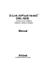
I. Physical Installation
Congratulations on your purchase of ARMC/3P, the complete solution for secure remote platform management. This
very important installation procedure ensures a smooth installation.
Mount the ARMC/3P into a free PCI slot. You may use a PCI-X slot (33 or 66 MHz, 32 or 64 Bit). The ARMC/3P will not
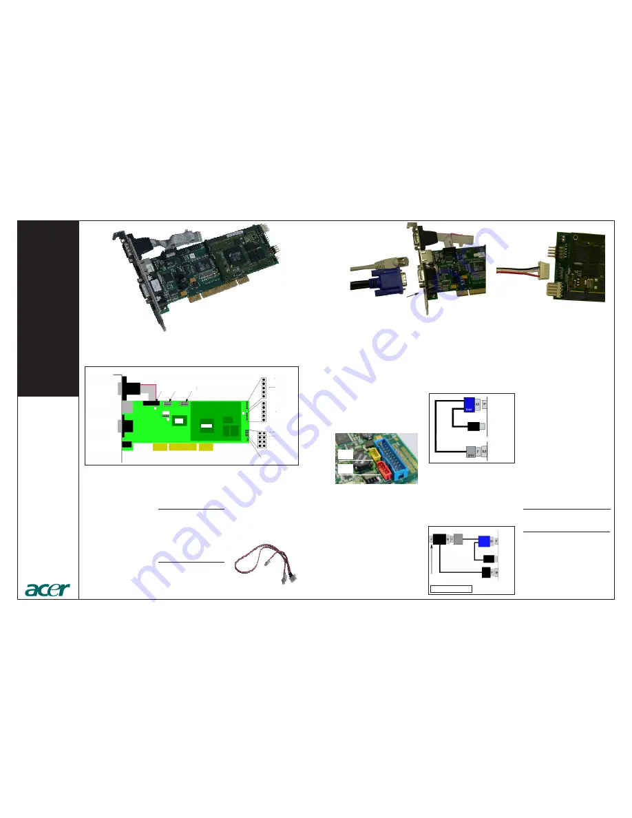
fit in PCI express slots. Connect the cables like shown in the figure:
ARMC/3P
USB
at host
VGA
outoput
IPMB Cable
IPMB
Type A
IPMB
type B
VGA-USB System Cable
Videosplitter
To the local Monitor
F - female connector
M - male connector
VGA
output
USB
at host
ARMC/3P
VGA-USB System Cable
Serial 1
Ethernet
KVM Port
External Power
Adaptor
1
1
USB
Serial 1
Serial 2
PS/2
ADC
KIRA100
ATX Power Cable Adaptor
IPMB
Reset/Power Wires
S2D
cable color
purple
black
red
white
black
-
-
RST1
RST2
PWR1
PWR2
VGA-USB System Cable
Ethernet
ARMC/3P Front Side Connectors
ARMC/3P Rear Side Connectors
IPMB cable
optional External
Power Supply
1