background image

ICONIA Tab A100/A101

SERVICE 

GUIDE

Summary of Contents for A100

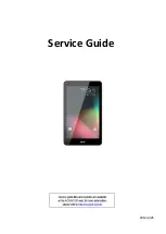
Page 1: ...ICONIA Tab A100 A101 SERVICE GUIDE ...

Page 2: ...cal magnetic optical chemical manual or otherwise without the prior written permission of Acer Incorporated Disclaimer The information in this guide is subject to change without notice There are no representations or warranties either expressed or implied with respect to the contents hereof and specifically disclaims any warranties of merchantability or fitness for any particular purpose The softw...

Page 3: ... this document Book titles directory names file names path names and program process names are shown in italics Example the DRS5 User s Guide usr local bin fd the TPH15spool_M program Computer output text that represents information displayed on a computer screen such as menus prompts responses to input and error messages are shown in constant width Example 01 The server has been stopped User inpu...

Page 4: ...eneric service guide In such cases contact your regional offices or the responsible personnel channel to provide further technical details When ordering FRU parts Check the most up to date information available on your regional Web or channel If for whatever reason a part number change is made it may not be noted in this printed service guide Acer authorized Service Providers Your Acer office may ...

Page 5: ...ccessories 1 8 Notebook Tour 1 9 Front View 1 9 Rear View 1 10 Top View 1 11 Left View 1 12 Right View 1 13 System Block Diagram 1 15 Specification Tables 1 16 Computer specifications 1 16 System Board Major Chips 1 17 Processor 1 17 Processor Specifications 1 18 System Memory 1 18 Video Interface Integrated 1 19 LAN Interface 1 20 LED 7 1 1 22 Display Supported Resolution LCD 1 23 Display Support...

Page 6: ... Diagnostic Tools 2 3 NGA EUU Installation Procedure 2 3 Picasso Diagnostic Tool 2 11 CHAPTER 3 Maintenance Procedures Introduction 3 3 General Information 3 3 Recommended Equipment 3 3 Maintenance Flowchart 3 4 Getting Started 3 5 SIM Micro SD Card Removal 3 6 SIM Micro SD Card Installation 3 7 Lower Case Removal 3 8 Lower Case Installation 3 15 Battery Removal 3 16 Battery Installation 3 18 3G M...

Page 7: ...val 3 43 WLAN Antenna Installation 3 43 Home Key Board Removal 3 44 Home Key Board Installation 3 45 CHAPTER 4 Troubleshooting Introduction 4 3 General Information 4 3 Power On Issues 4 4 No Display Issues 4 5 LCD Picture Failure 4 6 Touch Screen Failure 4 7 Internal Speaker Failure 4 8 Internal Microphone Failure 4 9 USB Failure mini USB Failure 4 10 Front Camera Failure 4 11 Back Camera Failure ...

Page 8: ...Field Replaceable Unit List Exploded Diagrams 6 4 Main Assembly 6 4 FRU List 6 6 Screw List 6 9 CHAPTER 7 Model Definition and Configuration A100 7 3 A101 7 14 CHAPTER 8 Test Compatible Components Android OS Environment Test 8 4 A100 A101 8 4 CHAPTER 9 Online Support Information Introduction 9 3 ...

Page 9: ...CHAPTER 1 Hardware Specifications ...
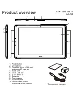
Page 10: ... View 1 10 Top View 1 11 Left View 1 12 Right View 1 13 System Block Diagram 1 15 Specification Tables 1 16 Computer specifications 1 16 Processor 1 17 Processor Specifications 1 18 System Memory 1 18 Video Interface Integrated 1 19 LAN Interface 1 20 LED 7 1 1 22 Display Supported Resolution LCD 1 23 Display Supported Resolution GPU 1 23 Bluetooth Interface 1 23 Camera 1 24 Mini Card 1 24 3G Card...

Page 11: ...1 3 AC Adapter 1 26 System Power Management 1 26 Card Reader 1 27 System LED Indicator 1 27 System DMA Specification 1 27 ...

Page 12: ...1 4 ...

Page 13: ...DR2 up to 1GB POP type discrete on board eMMC 8G default LCM 0 7 WSVGA LCM 1024 600 CMI and CPT View angle 70 degree at least at each 4 site LVDS interface Network 0 2G GSM GPRS EDGE 850MHz 900MHz 1800Mhz 1900Mhz 3G Module Erisson F5521gw with GPS AGPS UMTS WCDMA 1 2 5 8 2100 1900 850 900 HSPA HSDPA up to 21Mbps HSUPA up to 5 76Mbps GSM GPRS EDGE 850MHz 900MHz 1800Mhz 1900Mhz GPS 0 WIFI SKU Broadc...

Page 14: ...e Fast camera ready time 2 sec from camera key press to ready to capture state Front camera 2M FF Connectivity 0 BRCM 4329 Wi Fi IEEE 802 11b g n and Bluetooth 2 1 extendable to 3 0 USB Micro USB 2 0 support Input 0 Capacitive Multi Touch Screen 5 4 points control IC Cypress Function buttons Side mechanical key Volume Up Volume Down screen lock Power with back light white orange Lighting Behaviors...

Page 15: ...eable Lithium ion or polymer battery Sony 454261 Polymer cell Sanyo 484462 prismatic cell Capacity 11 3W 1530 mAh cell 2S1P Battery life TBD Video playback 5 hours when play 720P H 264 video playback on system not streaming Wifi 3G BT off 50 brightness Stand by 250 hours LCD off Web surfing WIFI SKU up to 5 hours 3G SKU up to 4 hours Youtube playback 720p video for 5 2hours via WIFI 3 6 hours via ...

Page 16: ...1 8 Hardware Specifications and Configurations Others 0 Reset hole Docking support HDMI power audio Accessories 0 In Box Charger Plug QSG Optional Earphone Micro SD Card Docking IR remote Pouch ...

Page 17: ...Specifications and Configurations 1 9 Notebook Tour 0 Front View 0 Figure 1 1 Front View Table 1 1 Front View Icon Item Description 1 Front Camera 2M Pixel CCD 2 Light Sensor 3 Touch Window 4 Home Button 1 2 3 4 ...

Page 18: ...1 10 Hardware Specifications and Configurations Rear View 0 Figure 1 2 Front View Table 1 2 Front View Icon Item Description 1 Rear Camera 5M Pixel CCD 2 LED Flash 2 1 ...

Page 19: ...d Configurations 1 11 Top View 0 Figure 1 3 Top View Table 1 3 Top View Icon Item Description 1 Rotation Lock switch Screen Rotation Control Lock switch 2 Volume Control Key 3 Card Slots SIM microSD card slot only for A101 1 2 3 ...

Page 20: ...pecifications and Configurations Left View 0 Figure 1 4 Left View Table 1 4 Left View Icon Item Description 1 Headphones Speaker Jack 2 Power Resume Button Power on machine or resume from sleep mode 3 Microphone 1 2 3 ...

Page 21: ...d Configurations 1 13 Right View 0 Figure 1 5 Right View Table 1 5 Right View Icon Item Description 1 Reset Button 2 micro HDMI Port Micro Type D HDMI port 3 Docking Port 4 micro USB Connector 5 DC IN Jack 6 Speakers 1 6 2 3 4 5 ...

Page 22: ...1 14 Hardware Specifications and Configurations Bottom View N A 0 Figure 1 6 Bottom View Table 1 6 Bottom View Icon Item Description ...

Page 23: ...MI Power Switch Current Limit 5V GPIO ULPI PHY SMSC USB3315 DAP_MCLK2 ULPI_Reset ULPI DATA USB2 Signal Switch 1 8V SDIO1 3G Modem Module with HSPA MSM6290 U335 F3607gw 3G Modem Antenna USB D D USB2 WLAN BT Client Charger IC BQ24725 Adapter in 12V 1 5A 18W 5VALW 3VALWS LDO PMIC TPS658621 PWR_I2C 32KHz VIN SM1 SM0 LDO2 SM0_EN 32K_OUT SCLK SDAT SM1_EN nRESET PWR_I2C 1 8V VDD_RTC VDD_CORE VDDIO_UART n...

Page 24: ...al disc 0 C to 50 C 32 F to 122 F Operating writing to optical disc 0 C to 50 C 32 F to 122 F Nonoperating 20 C to 60 C 4 F to 140 F Relative humidity Operating 10 to 90 Nonoperating 5 to 95 Maximum altitude unpressurized Operating 15 m to 3 048 m 50 ft to 10 000 ft Nonoperating 15 m to 12 192 m 50 ft to 40 000 ft Shock Operating 125 g 2 ms half sine Nonoperating 200 g 2 ms half sine Random vibrat...

Page 25: ...ntroller integrated with CPU LVDS transmitter SN75LVDS83B PMU TI TI TPS658621C LDDR2 Elpida EDB8132B2PB 1GB ULPI Phy for USB SMSC USB3315 GPS Broadcom BCM4751 TOUCH controller Cypress eMMC 8GB CAMERA Chicony CJAA525 5M pixel Chicony CJFB21120003350LH 2M pixel Thermal Sensor Onsemi NTC1008 Battery Charger TI BQ24617 Compass Asahi Kasei AKM8975C Gyro Invensense MPU 3050 ALS Proximity Lite On AL3000A...

Page 26: ...Package Voltage T20 1 GHz 2 Cores 64 bits 40 nm 1 MB 23x23 FCBGA 1 0 1 2V CPU Temperature Fan Speed RPM SPL Spec dBA 60 70 80 90 100 Item Specification Memory controller Build in CPU Memory size 1GB LPDDRII DIMM socket number N A Supports memory size per socket N A Supports maximum memory size N A Supports DIMM type N A Supports DIMM Speed N A Support DIMM voltage N A Supports DIMM package N A ...

Page 27: ...dware Specifications and Configurations 1 19 Memory Combinations N A Video Interface Integrated Slot 1 MB Slot 2 MB Total Memory MB Item Specification Chipset Package Interface Compatibility Sampling rate ...

Page 28: ...fication LAN Chipset N A No LAN Port LAN connector type N A No LAN Port LAN connector location N A No LAN Port Features UMTS WCDMA a 3G dual band b 3G qual band c LTE n HSDPA up to 7 2Mbps HSUPA up to 5 76Mbps n GSM GPRS EDGE 850MHz 900MHz 1800Mhz 1900Mhz Item Specification Type Total number of keypads Windows logo key Internal external keyboard work simultaneously Features ...

Page 29: ...Drive Format Disks Spindle speed RPM Performance Specifications Buffer size Interface Fast data transfer rate Mbits sec max Media data transfer rate Mbytes sec max DC Power Requirements Voltage tolerance Item Specification Vendor Model name Performance Specification Transfer rate KB sec Buffer Memory Interface Applicable disc format Loading mechanism Power Requirement Input Voltage ...

Page 30: ...ive Area mm 222 72 mm x 125 28 mm Display resolution pixels 1024 x 3 RGB x 600 Pixel Pitch mm 0 2175mm 0 2088 mm Typical White Luminance cd m2 also called Brightness 200 cd m2 Contrast Ratio 400 min 500 type Response Time Optical Rise Time Fall Time msec 8 ms 12 ms Typical Power Consumption watt 2 17 W Weight without inverter 190g max Physical Size mm 235 5 mm x 143 5 mm x 5 2mm max Electrical Int...

Page 31: ...v Input current mA Output voltage V RMS Output current mA RMS Output voltage frequency KHz Resolution 16 bits 32 bits Intel NVIDIA ATI 1024x 3 RGB x 600 X X X V X Item Specification VGA Chip Supports Resolution 16 bits 32 bits Intel NVDIA ATI 1024x 3 RGB x 600 X X X V X Item Specifications Chipset Aruzewave AW NH611 SiP module Data throughput TX 1 2Mbits sec RX 1 2Mbits sec Protocol 2 1 EDR Interf...

Page 32: ...olfson WM8903 Features 4 5mW Power consumption for DAC to headphone playback DAC SNR 96dB typical THD 86dB typical ADC SNR 92dB typical THD 80dB typical Control sequencer for pop minimized start up and shut down Single register write for default start up sequence Stereo digital microphone input 3 single ended inputs per stereo channel 2 pseudo differential inputs per stereo channel 1 fully differe...

Page 33: ...e up to 44 1KHz Internal microphone Yes Internal speaker quantity Yes 1W speakers x2 Item Specification Chipset Azurewave AW NH611 Broadcom BCM4329 SoC Data throughput 802 11b g 11 54 Mbps 802 11n MCS 0 7 Protocol IEEE 802 11b g n Interface SDIO SPI interface Item Specification Vendor Model name SANYO BAT 711 Battery Type Li ion Pack capacity 1530 mAh Number of battery cell 2 Package configuration...

Page 34: ...million colors Number of HDMI port s 1 Location one at the right side Item Specification Input rating 18W Maximum input AC current 0 5A RMS at 100Vac Inrush current 60A Max 230Vac Efficiency Refer to EPS 2 0 standard level V Item Specification Mech Off G3 Only EC working Soft Off G2 S5 Only EC working Working G0 S0 Individual devices such as the CPU and eMMC may be power managed in this state Susp...

Page 35: ...te color and amber color off System off suspend Amber color Battery in charging HDD access state N A Wireless state N A Power button backlight Amber while charging Blue while charging complete Battery state Power button Amber while charging Blue while charging complete Legacy Mode Power Management DMA0 Not applicable DMA1 Not applicable DMA2 Not applicable DMA3 Not applicable DMA4 Direct memory ac...

Page 36: ...tion IRQ0 IRQ1 IRQ2 IRQ3 IRQ5 IRQ6 IRQ7 IRQ8 IRQ9 IRQ10 IRQ11 IRQ12 IRQ13 IRQ14 IRQ15 Default configuration audio possible configurations are IRQ5 IRQ7 IRQ9 IRQ10 or none NOTE ExpressCards may assert IRQ3 IRQ4 IRQ5 IRQ7 IRQ9 IRQ10 IRQ11 or IRQ15 Either the infrared or the serial port may assert IRQ3 or IRQ4 ...

Page 37: ... Keyboard controller 061 Port B 062 063 Unused 064 Keyboard controller 065 06F Unused 070 071 NMI enable RTC 072 07F Unused 080 08F DMA page registers 090 091 Unused 092 Port A 093 09F Unused 0A0 0A1 Interrupt controller no 2 I O Address hex System function shipping configuration 0A2 0BF Unused 0C0 0DF DMA controller no 2 0E0 0EF Unused 0F0 0F1 Coprocessor busy clear reset 0F2 0FF Unused 100 16F U...

Page 38: ...nused 2F8 2FF Infrared port 300 31F Unused 320 36F Unused 370 377 Secondary diskette drive controller 378 37F Parallel port LPT1 default 380 387 Unused 388 38B FM synthesizer OPL3 38C 3AF Unused 3B0 3BB VGA 3BC 3BF Reserved parallel port no EPP support 3C0 3DF VGA 3E0 3E1 ExpressCard controller in CPU 3E2 3E3 Unused 3E8 3EF Internal modem 3F0 3F7 A diskette controller 3F8 3FF Serial port COM1 defa...

Page 39: ...CHAPTER 2 Diagnostic Utilities ...

Page 40: ...2 2 Introduction 2 3 Diagnostic Tools 2 3 NGA EUU Installation Procedure 2 3 Picasso Diagnostic Tool 2 11 ...

Page 41: ...tility guide click here NGA EUU Installation Procedure 0 NOTE NOTE Before installing EEU software make sure ICONIA tablet is not connected to a computer 1 Install EUU software on a PC When the following dialog is shown click OK to continue Figure 2 1 Starting Installation 2 Select installation procedure language from drop down list Click Next to continue or Cancel to exit program Figure 2 2 Instal...

Page 42: ... Install USB driver Figure 2 3 Figure 2 3 USB Driver Installation 4 To enable USB debugging on the device go to the Settings Applications Development menu and click the USB debugging checkbox Figure 2 4 Figure 2 4 USB Debugging ...

Page 43: ...Figure 2 5 to find OS image version Figure 2 5 Finding OS Image Version 6 If image version is not available follow instructions in Figure 2 6 to manually reset device When procedure is complete go to Step 1 of this procedure Figure 2 6 Device Reset Instructions ...

Page 44: ...vailable current and new version information is shown Click Next to continue Figure 2 7 Figure 2 7 Image Versions 8 Enter CPU ID of device Click Next to continue Figure 2 8 NOTE NOTE Maximum number of characters for ID is sixteen 16 Figure 2 8 CPU ID ...

Page 45: ... process will not complete if USB cable is unplugged Figure 2 9 Upgrade Process 10 If upgrade process is successful Figure 2 10 is shown If an upgrade error is shown go to step 12 If a CPU ID value error is identified go to step 19 Figure 2 10 Upgrade Process Success 11 Click Finish to exit ...

Page 46: ...ocess Failure 13 Click Retry to start upgrade process Go to Step 8 14 Click Exit to cancel upgrade process 15 If upgrade process is cancelled a confirmation dialog is shown Figure 2 12 Figure 2 12 Upgrade Process Cancellation Confirmation Dialog 16 Click No to return to Retry dialog in Step 12 17 Click Yes to confirm cancellation ...

Page 47: ... Cancellation Dialog 19 If CPU ID value is not correct Figure 2 14 is shown Figure 2 14 Wrong CPU ID 20 Click Retry to start upgrade process Go to Step 8 21 Click Exit to cancel upgrade process Upgrade process failed because wrong CPU ID value was entered Follow instructions for recovery ...

Page 48: ...confirmation dialog is shown Figure 2 15 Figure 2 15 Upgrade Process Cancellation Confirmation Dialog 23 Click No to return to Retry dialog in Step 19 24 Click Yes to confirm cancellation 25 Click OK to exit program Figure 2 16 Figure 2 16 Final Cancellation Dialog ...

Page 49: ...Diagnostic Utilities 2 11 Picasso Diagnostic Tool 0 ...

Page 50: ...2 12 Diagnostic Utilities ...

Page 51: ......

Page 52: ......

Page 53: ......

Page 54: ......

Page 55: ......

Page 56: ......

Page 57: ......

Page 58: ......

Page 59: ......

Page 60: ......

Page 61: ......

Page 62: ......

Page 63: ......

Page 64: ......

Page 65: ......

Page 66: ......

Page 67: ......

Page 68: ......

Page 69: ......

Page 70: ......

Page 71: ......

Page 72: ......

Page 73: ......

Page 74: ......

Page 75: ......

Page 76: ......

Page 77: ......

Page 78: ......

Page 79: ......

Page 80: ......

Page 81: ......

Page 82: ......

Page 83: ......

Page 84: ......

Page 85: ......

Page 86: ......

Page 87: ......

Page 88: ......

Page 89: ......

Page 90: ......

Page 91: ......

Page 92: ......

Page 93: ......

Page 94: ......

Page 95: ......

Page 96: ......

Page 97: ......

Page 98: ......

Page 99: ......

Page 100: ......

Page 101: ...CHAPTER 3 Maintenance Procedures ...

Page 102: ... 24 Speakers Installation 3 26 IO Board FPC Removal 3 27 IO Board FPC Installation 3 28 IO Board Removal 3 29 IO Board Installation 3 30 Microphone Module Removal 3 32 Microphone Module Installation 3 32 3G Antenna Removal 3 33 3G Antenna Installation 3 33 Light Sensor Module Removal 3 34 Light Sensor Module Installation 3 34 GPS Antenna Removal 3 35 GPS Antenna Installation 3 35 Mainboard Removal...

Page 103: ...represent the final product color or configuration Cable paths and positioning may also differ from the actual model During the removal and installation of components make sure all available cable channels and clips are used and that the cables are installed in the same position All prerequisites must be performed prior to performing maintenance Recommended Equipment 0 The following tools are requ...

Page 104: ...ce Flowchart 0 The flowchart in Figure 3 1 provides a graphic representation of the module removal and installation sequences It provides information on what components need to be removed and installed during servicing Figure 3 1 Maintenance Flow ...

Page 105: ...erforming any maintenance procedures 1 Place system on a flat work surface 2 Make sure device is powered up 3 Disconnect AC Adapter A and remove all cables from system and peripherals Figure 3 2 Figure 3 2 Device Overview with Power Button 4 Power down the system by pressing and holding power button B for 4 seconds to show Tablet Options dialog Figure 3 3 Figure 3 3 Tablet Options Dialog 5 Select ...

Page 106: ...OTE NOTE SIM Micro SD card not available in non 3G SKU 1 Open SIM Micro SD card cover Figure 3 4 Figure 3 4 SIM micro SD Card Removal 2 Press in SIM card B to unlock and remove from spring locking mechanism Figure 3 5 Figure 3 5 SIM micro SD Card Slots 3G SKU A B C ...

Page 107: ... from spring locking mechanism Figure 3 5 and Figure 3 6 4 Secure SIM Micro SD card cover SIM Micro SD Card Installation 0 1 Open SIM Micro SD card cover A Figure 3 4 2 Install and press in to secure SIM card B Figure 3 5 3 Install and and press in to secure Micro SD card C 4 Close and secure SIM Micro SD card cover C ...

Page 108: ...ce Procedures Lower Case Removal 0 Prerequisite SIM Micro SD Card Removal 1 Starting from top of device release top cover Figure 3 7 and Figure 3 8 Figure 3 7 Releasing Top Cover 1 of 2 Figure 3 8 Releasing Top Cover 2 of 2 ...

Page 109: ...ures 3 9 2 Rotate the device and continue to remove all the covers from the right bottom and left sides of the bezel Figure 3 9 through Figure 3 14 Figure 3 9 Releasing Right Cover 1 of 2 Figure 3 10 Releasing Right Cover 2 of 2 ...

Page 110: ...3 10 Machine Maintenance Procedures Figure 3 11 Releasing Bottom Cover 1 of 2 Figure 3 12 Releasing Bottom Cover 2 of 2 ...

Page 111: ...Machine Maintenance Procedures 3 11 Figure 3 13 Releasing Left Cover 1 of 2 Figure 3 14 Releasing Left Cover 2 of 2 ...

Page 112: ...3 12 Machine Maintenance Procedures 3 Remove screws A from top and bottom of bezel Figure 3 15 and Figure 3 16 Figure 3 15 Bezel Screws 1 of 2 Figure 3 16 Bezel Screws 2 of 2 A A ...

Page 113: ...enance Procedures 3 13 4 Grasp lower case and bezel as shown in Figure 3 17 Figure 3 17 Removing Lower Case 1 of 3 5 Separate lower case from bezel locking latches Figure 3 18 Figure 3 18 Removing Lower Case 2 of 3 ...

Page 114: ...3 14 Machine Maintenance Procedures 6 Remove lower case from bezel Figure 3 19 Figure 3 19 Removing Lower Case 3 of 3 ...

Page 115: ...tall and secure lower case locking latches not shown on bezel 2 Install and secure screws A on bezel Figure 3 15 and Figure 3 16 3 Install and secure top right bottom and left side covers to bezel Figure 3 9 through Figure 3 14 ID Size Quantity Screw Type A M2 0x3 0 4 ...

Page 116: ...Procedures Battery Removal 0 Prerequisite Lower Case Removal 1 Locate battery A on shield case Figure 3 20 Figure 3 20 Battery 2 Disconnect battery cable B from mainboard connector C Figure 3 21 Figure 3 21 Battery Cable A C B ...

Page 117: ...Machine Maintenance Procedures 3 17 3 Remove screws D from shielding case Figure 3 22 and Figure 3 23 Figure 3 22 Battery Screws 1 of 2 Figure 3 23 Battery Screws 2 of 2 D D ...

Page 118: ...ery from shield case Battery Installation 0 1 Install battery A on shielding case Figure 3 20 NOTE NOTE Place cables E between battery and 3G module Figure 3 24 2 Install and secure screws D to shielding case Figure 3 22 and Figure 3 23 3 Connect battery cable B to mainboard connector C Figure 3 21 4 Install lower case ID Size Quantity Screw Type A M2 0x4 0 Ni 4 E ...

Page 119: ... Locate 3G module A on LCD support plate Figure 3 25 Figure 3 25 3G Module Overview 2 Disconnect GPS C and RF B cables from 3G module connectors labeled aux and main Figure 3 26 Figure 3 26 3G RF and WLAN Cables 3 Disconnect WLAN main D cable from mainboard connector Figure 3 26 A B C D ...

Page 120: ...ove screw E from shielding case Figure 3 27 3G Module Mainboard Connector and 3G Screw 5 Remove 3G module A from mainboard connector a 6 Disconnect RF cable F from IO board connector Figure 3 28 Figure 3 28 RF Cable 7 Remove RF cable F a E A F ...

Page 121: ...e 3 27 3 Install and secure screw E to mainboard CAUTION Route the WLAN antenna around the IO board FPC to prevent it from being disconnected from mainboard 4 Connect WLAN antenna D to mainboard connector Figure 3 26 5 Connect GPS C and RF B cables to 3G module connectors labeled auxiliary and main 6 Install battery ID Size Quantity Screw Type E M2 0x3 0 1 ...

Page 122: ...y Removal 1 Locate DC IN cable A on bezel Figure 3 29 Figure 3 29 DC IN Cable Overview 2 Disconnect DC IN cable A from mainboard connector B Figure 3 30 Figure 3 30 DC IN Cable Jack and Mainboard Connector 3 Remove DC IN cable jack C from bezel guide 4 Remove DC IN cable A B A C ...

Page 123: ...Machine Maintenance Procedures 3 23 DC In Cable Installation 0 1 Install and secure DC IN jack on bezel Figure 3 30 2 Connect DC In cable A to mainboard connector B 3 Install lower case ...

Page 124: ... Removal 0 Prerequisite Battery Removal 1 Locate speaker modules A on bezel Figure 3 31 Figure 3 31 Speaker Modules Overview 2 Disconnect Home key FFC B from mainboard connector C Figure 3 32 Figure 3 32 Speaker Module FFC and Mainboard Connector A B C ...

Page 125: ...res 3 25 3 Disconnect speaker cable D from mainboard connector E Figure 3 33 Figure 3 33 Speaker Modules Overview 4 Remove screws F from LCD support plate Figure 3 34 and Figure 3 35 Figure 3 34 Speaker Module Screws 1 of 2 D E F ...

Page 126: ...stallation 0 1 Install speakers A on bezel Figure 3 31 2 Install and secure screws F to support plate Figure 3 34 and Figure 3 35 3 Connect speaker cable D to mainboard connector E Figure 3 33 4 Connect home key FFC B to mainboard connector C Figure 3 32 5 Install battery ID Size Quantity Screw Type F M2 0x4 0 Ni 2 F ...

Page 127: ...moval 3G SKU 1 Locate IO Board FPC A Figure 3 36 Figure 3 36 IO Board FPC Overview 2 Remove adhesive tape B securing FPC to support plate Figure 3 37 Figure 3 37 IO Board FPC and Mainboard Connectors 3 Disconnect FPC A from mainboard connector C 4 Disconnect FPC A from IO board connector D 5 Remove FPC A B A D C ...

Page 128: ...ures IO Board FPC Installation 0 1 Connect FPC A to mainboard connector C Figure 3 37 2 Connect FPC A to IO board connector D 3 Install tape B on FPC and secure to support plate 4 Install battery non 3G SKU 5 Install 3G module 3G SKU ...

Page 129: ... Figure 3 38 IO Board Overview 2 Disconnect 3G antenna cable B from IO board connector Figure 3 39 Figure 3 39 IO Board Cables and Screw 3 Disconnect microphone cable C from IO board connector D 4 Disconnect light sensor cable E from IO board connector F 5 Remove screw G from bezel 6 Remove board from bezel A B C D G E F ...

Page 130: ...n 0 1 Connect RF cable H to IO board connector Figure 3 40 NOTE NOTE Light sensor must be secured in support plate guide Microphone cable must be under IO board 2 Align IO board with bezel guides J Figure 3 41 NOTE NOTE RF cable must be secured under IO board guides K Figure 3 41 IO Board and Bezel Guides 3 Install board on bezel H J J K ...

Page 131: ...ure screw G to bezel Figure 3 39 5 Connect light sensor cable E to IO board connector F 6 Connect microphone cable C to IO board connector D 7 Connect 3G antenna cable B to IO board connector 8 Install IO Board FPC ID Size Quantity Screw Type G M2 0x3 0 1 ...

Page 132: ...te microphone module A Figure 3 42 Figure 3 42 Microphone Module Overview 2 Remove microphone A from bezel guides Microphone Module Installation 0 1 Install and secure microphone A in bezel guide B facing out Figure 3 43 Figure 3 43 Installing Microphone Module in Bezel Guide 2 Install IO Board A A B ...

Page 133: ... 1 Locate 3G Antenna A Figure 3 44 Figure 3 44 3G Antenna Overview 2 Release 3G antenna foil B secured to support plate 3 Remove 3G antenna from bezel 3G Antenna Installation 0 1 Install 3G antenna A on bezel Figure 3 44 2 Secure 3G antenna foil B on support plate 3 Install IO Board A B ...

Page 134: ...t sensor module A Figure 3 45 Figure 3 45 Light Sensor Module Overview 2 Remove light sensor module A from bezel Light Sensor Module Installation 0 1 Install and secure light sensor module A Figure 3 45 in clips in bezel guides B Figure 3 46 Figure 3 46 Light Sensor Module Bezel Guides 2 Install IO Board A B B ...

Page 135: ...cate GPS Antenna A Figure 3 47 Figure 3 47 GPS Antenna Overview 2 Release GPS antenna foil B secured to support plate 3 Remove GPS antenna A from bezel GPS Antenna Installation 0 1 Install GPS antenna A on bezel Figure 3 47 2 Secure GPS antenna foil B on support plate 3 Install 3G module 3G SKU 4 Install speaker modules non 3G SKU A B ...

Page 136: ...r Module Removal IO Board FPC Removal 1 Locate mainboard A Figure 3 48 Figure 3 48 Mainboard Overview 2 Disconnect LVDS cable B from mainboard connector C Figure 3 49 Figure 3 49 LVDS Cable and Mainboard Connector 3 Remove tape D securing touch screen FPC to mainboard A B C D ...

Page 137: ...3 37 4 Disconnect touch screen FPC E from mainboard connector F Figure 3 50 Figure 3 50 Touch Screen FPC and Mainboard Connector 5 Remove screws G from bezel Figure 3 51 through Figure 3 53 Figure 3 51 Mainboard Screws 1 of 3 E F G G ...

Page 138: ...3 38 Machine Maintenance Procedures Figure 3 52 Mainboard Screws 2 of 3 Figure 3 53 Mainboard Screws 3 of 3 6 Remove mainboard from support plate G G ...

Page 139: ...d secure screws G to bezel Figure 3 51 through Figure 3 53 3 Connect touch screen FPC E to mainboard connector F Figure 3 50 4 Install tape D securing touch screen to mainboard Figure 3 49 5 Connect LVDS cable B to mainboard connector C 6 Install speaker modules 7 Install IO Board FPC ID Size Quantity Screw Type G M2 0x3 0 4 ...

Page 140: ...rd Removal 0 Prerequisite Mainboard Removal 1 Place bottom of mainboard on a flat surface Figure 3 54 Figure 3 54 Mainboard Overview 2 Locate rear CCD board A 3 Remove screws B from CCD to mainboard Figure 3 55 Figure 3 55 Rear CCD Board Screws A B B ...

Page 141: ...intenance Procedures 3 41 4 Disconnect and remove rear CCD board A from mainboard connector C Figure 3 56 and Figure 3 57 Figure 3 56 Removing Rear CCD Board 1 of 2 Figure 3 57 Removing Rear CCD Board 2 of 2 C A ...

Page 142: ...1 Connect CCD board A to mainboard connector C Figure 3 58 Figure 3 58 Installing Rear CCD Board 1 of 2 Figure 3 59 Installing Rear CCD Board 2 of 2 2 Install and secure screws B to mainboard Figure 3 55 3 Install mainboard ID Size Quantity Screw Type B M2 0x3 0 2 A C ...

Page 143: ...te WLAN antenna A Figure 3 60 Figure 3 60 WLAN Antenna Overview 2 Release WLAN antenna foil B secured to support plate 3 Remove WLAN antenna A from bezel WLAN Antenna Installation 0 1 Install WLAN antenna A on bezel Figure 3 60 2 Secure WLAN antenna foil B on support plate 3 Install mainboard A B ...

Page 144: ...l 0 Prerequisite Mainboard Removal 1 Locate home key board A Figure 3 61 Figure 3 61 Home Key Board Overview 2 Remove home key board A from bezel 3 Disconnect home key FFC B from board connector C Figure 3 62 Figure 3 62 Home Key FFC and Board Connector A B C ...

Page 145: ...rd Installation 0 1 Connect home key FFC B to board connector C Figure 3 62 2 Align home key board with bezel guide D Figure 3 63 Figure 3 63 Home Key Board Bezel Guide 3 Install and secure home key board A to bezel Figure 3 61 4 Install mainboard D ...

Page 146: ...3 46 Machine Maintenance Procedures ...

Page 147: ...CHAPTER 4 Troubleshooting ...

Page 148: ... Failure 4 8 Internal Microphone Failure 4 9 USB Failure mini USB Failure 4 10 Front Camera Failure 4 11 Back Camera Failure 4 12 P Sensor Failure 4 13 3G Function Failure 4 14 Wireless Function Test Failure 4 15 GPS Function Test Failure Wi Fi SKU 4 16 GPS Function Test Failure 3G SKU 4 17 Docking Station Test Failure 4 18 Other Functions Failure 4 19 ...

Page 149: ...ssible about the problem 2 If possible verify the symptoms by re creating the failure through diagnostic tests or repeating the operation that led to the problem 3 Use Table 4 1 with the verified symptom to determine the solution 4 If the Issue is still not resolved refer to Online Support Information Table 4 1 Verified Symptoms Symptoms Verified Power On Issues No Display Issues LCD Picture Failu...

Page 150: ...4 4 Troubleshooting Power On Issues 0 If the system fails perform the following Figure 4 1 Power On Issues Start Check AC cable BATT only power on Swap AC cable BATT OK OK NG Swap M B ...

Page 151: ...splay Issues 0 If the display fails perform the following Figure 4 2 No Display Issues Start Can power on Check LCD cable LCD panel Go to no power Trouble shoo ng step swap LCD cable Swap LCD panel OK OK OK OK NG NG NG Swap M B ...

Page 152: ...roubleshooting LCD Picture Failure 0 If the LCD picture fails perform the following Figure 4 3 LCD Picture Failure Start Check LCD cable Check LCD panel Swap LCD cable Swap LCD panel OK OK OK NG NG Swap M B ...

Page 153: ...h screen fails perform the following Figure 4 4 Touch Screen Failure Start Check touch screen small B Check touch screen panel Swap M B Check touch screen cable Swap touch screen cable Swap touch screen small B Swap touch screen panel OK OK OK OK NG NG NG ...

Page 154: ...4 8 Troubleshooting Internal Speaker Failure 0 If the internal speakers fail perform the following Figure 4 5 Internal Speaker Failure Start Check SPK Swap M B Swap SPK OK OK NG ...

Page 155: ...If the internal microphone fails perform the following Figure 4 6 Internal Microphone Failure Start Check the back MIC Swap M B Swap the back MIC OK OK NG Check the front MIC and the back MIC Check the front MIC Swap M B Swap the front MIC OK NG OK OK ...

Page 156: ...hooting USB Failure mini USB Failure 0 If the USB fails perform the following Figure 4 7 USB Failure Start Check the USB B to M B FFC Check the USB B Swap M B Swap the USB B to M B FFC Swap the USB B OK OK OK NG NG ...

Page 157: ...Troubleshooting 4 11 Front Camera Failure 0 If the front camera fails perform the following Figure 4 8 Front Camera Failure Start Check the front camera Swap M B Swap the front camera OK OK NG ...

Page 158: ...4 12 Troubleshooting Back Camera Failure 0 If the back camera fails perform the following Figure 4 9 Back Camera Failure Start Check the back camera Swap M B Swap the back camera OK OK NG ...

Page 159: ... Sensor Failure 0 If the P sensor fails perform the following Figure 4 10 P Sensor Failure Start Check conduc ve co on on the Lower Check related Mylar on the MB Swap M B Add conduc ve co on Add related Mylar OK OK OK NG NG ...

Page 160: ...oting 3G Function Failure 0 If the 3G function fails perform the following Figure 4 11 3G Function Failure Start Check the 3G antenna Check the 3G card Swap M B Swap the 3G Main antenna Swap the 3G card OK OK OK NG NG ...

Page 161: ...ubleshooting 4 15 Wireless Function Test Failure 0 If the wireless function fails perform the following Figure 4 12 Wireless Function Failure Start Check the W L antenna Swap M B Swap the antenna OK OK NG ...

Page 162: ...leshooting GPS Function Test Failure Wi Fi SKU 0 If the GPS function Wi Fi SKU test fails perform the following Figure 4 13 GPS Function Test Failure Start Check the GPS antenna Swap M B Swap the antenna OK OK NG ...

Page 163: ... Test Failure 3G SKU 0 If the GPS function test 3G SKU fails perform the following Figure 4 14 GPS Function Test Failure Start Check the 3G Aux antenna Check the 3G card Swap M B Swap the 3G Aux antenna Swap the 3G card OK OK OK NG NG ...

Page 164: ...est Failure 0 If the docking station test fails perform the following Figure 4 15 Docking Station Test Failure Start Check the Docking B to M B FFC Check the Docking B Swap M B Swap the Docking B to M B FFC Swap the Docking B OK OK OK NG NG ...

Page 165: ...Troubleshooting 4 19 Other Functions Failure 0 1 Check component connection to mainboard 2 To test for mainboard fault swap mainboard ...

Page 166: ...4 20 Troubleshooting ...

Page 167: ...CHAPTER 5 Jumper and Connector Locations ...

Page 168: ...5 2 Mainboard Top 5 3 Mainboard Bottom 5 4 ...

Page 169: ...ainboard Top Item Description Item Description U1 CPU Chip JP70 Micro USB Connector U129 LP DDR2 Chip JP12 Docking Connector JP67 Camera B Connector JHDMI1 Micro HDMI Connector JP10 Micro SD Card Connector SW6 Reset Switch JP2 SIM Card Connector JMIN2 3G Module Connector JP67 JP10 JP2 JP70 JP12 JHDMI1 SW6 JMIN2 U1 U129 ...

Page 170: ...m Description PJP1 AC IN Connector JMIN2 3G Module Connector ANT3 GPS Antenna Connector JLVDS3 LCD Panel Connector ANT5 WiFi Antenna Connector PJP2 Battery Connector JP5 IO B Connector JP55 Speaker Connector U19 eMMC Chip JP73 Home Key B Connector JP58 Touch Panel Connector ANT3 ANT5 JP5 U19 JP58 JMIN2 JLVDS3 PJP2 JP55 JP73 PJP1 ...

Page 171: ...CHAPTER 6 Field Replaceable Unit List ...

Page 172: ...6 2 Exploded Diagrams 6 4 Main Assembly 6 4 FRU List 6 6 Screw List 6 7 ...

Page 173: ...number changes will not be noted on the printed Service Guide For Acer Authorized Service Providers the Acer office may have a different part number code from those given in the FRU list of this printed Service Guide Users MUST use the local FRU list provided by the regional Acer office to order FRU parts for repair and service of customer machines NOTE NOTE To scrap or to return the defective par...

Page 174: ...6 4 FRU List Exploded Diagrams 0 Main Assembly 0 Figure 6 1 Main Assembly Exploded Diagram 12 13 14 15 11 9 16 2 3 4 5 6 7 8 10 1 ...

Page 175: ... 55 H6S02 001 5 MAINBOARD MB H6R00 001 6 SPEAKER L R 23 H6S02 002 7 TOP STRIP COVER 60 H6W02 001 8 RIGHT STRIP COVER 60 H6S02 005 9 BOTTOM STRIP COVER 60 H6S02 003 10 LOWER CASE IMR INCL CAMERA LENS 60 H6S02 001 11 FFC FOR IO BOARD 50 H6S02 002 12 IO BOARD 55 H6S02 002 13 MIC SET 23 H6S02 001 14 CAMERA 2M 57 H6S02 001 15 ANTENNA 3G 50 H6W02 002 16 ASSY TOUCH LCD MODULE 7 0 6M H6S02 001 ...

Page 176: ...ATTERY Battery SANYO BAT 711 Prismatic 2S1P SANYO 2 Cell 1530mAh Main COMMON BT 00203 005 BOARD CAMERA BOARD INCL 5M CAMERA FOR WIFI 55 H6S02 001 CAMERA BOARD INCL 5M CAMERA FOR 3G 55 H6V02 001 IO BOARD FOR 3G 55 H6S02 002 IO BOARD FOR WIFI 55 H6S02 004 HOME KEY BOARD 55 H6S02 003 HUAWEI EM820W LC 21300 068 Huawei EM770W Rev3 LC 21300 073 Ericsson F5521gw TAB LC 21300 074 F5521gw TAB AT T LC 21300...

Page 177: ...27 H6002 001 AC CLIP 18W AU 27 H6002 002 AC CLIP 18W ARG 27 H6002 003 AC CLIP 18W BRZ 27 H6002 004 CASE COVER BRACKET ASSEMBLY LOWER CASE IMR INCL CAMERA LENS 60 H6S02 001 TOP STRIP COVER FOR W 3G 60 H6W02 001 TOP STRIP COVER FOR W O 3G 60 H6S02 002 BOTTOM STRIP COVER 60 H6S02 003 RIGHT STRIP COVER 60 H6S02 005 LCD ASSEMBLY ASSY TOUCH LCD MODULE 7 0 6M H6S02 001 ANTENNA WLAN 50 H6S02 004 Table 6 2...

Page 178: ...NTENNA 3G US 50 H6V02 001 CAMERA 2M 57 H6S02 001 MAINBOARD Mainboard A100_8u Nvidia Tegra 250 Rev 1 0 W WIFI CPU RAM MB H6R00 001 Mainboard A100_16u Nvidia Tegra 250 Rev 1 0 W WIFI CPU RAM MB H6S00 001 SPEAKER MIC SET 23 H6S02 001 SPEAKER L R 23 H6S02 002 Table 6 2 FRU List Continued Category Description P N ...

Page 179: ... List 6 9 Screw List 0 Table 6 3 Screw List Category Description P N SCREW SCREW 2D 2 5L K 4 05D NI NL 86 H6S02 001 SCREW 2D 4 0L K 4 0D NI NL 0 3T 86 H6S02 002 SCREW 2 0D 3 0L K 3 6 ZK NL CR3 86 H6S02 003 ...

Page 180: ...6 10 FRU List ...

Page 181: ...CHAPTER 7 Model Definition and Configuration ...

Page 182: ...7 2 A100 7 3 A101 7 4 ...

Page 183: ...SEN 011 A100_16u EMEA EMEA A100 GCTWN XE H6RTN 001 A100_8u TWN GCTWN A100 GCTWN XE H6STN 001 A100_16u TWN GCTWN A100 HK XE H6RCN 001 A100_8u CHINA AFE A100 HK XE H6SCN 001 A100_16u CHINA AFE A100 ID XE H6RAN 003 A100_8u AAP AIN A100 ID XE H6SAN 003 A100_16u AAP AIN A100 IN XE H6RAN 002 A100_8u AAP AIL A100 IN XE H6SAN 002 A100_16u AAP AIL A100 IT XE H6REN 004 A100_8u EMEA AIT A100 IT XE H6SEN 003 ...

Page 184: ... XE H6REN 009 A100_8u EMEA ATR A100 TR XE H6SEN 002 A100_16u EMEA ATR A100 UK XE H6REN 006 A100_8u EMEA AUK A100 UK XE H6SEN 004 A100_16u EMEA AUK A100 US XE H6RPN 002 A100_8u PA AAC A100 US XE H6RPN 006 A100_8u PA AAC A100 US XE H6SPN 003 A100_16u PA AAC A100 US XE H6SPN 005 A100_16u PA AAC A100 VN XE H6RAN 009 A100_8u AAP AVN A100 VN XE H6SAN 007 A100_16u AAP AVN A100 WW S7 H6RWN 001 A100_8u WW ...

Page 185: ..._CUS3 AndroidBE 5 EU Blue Wi Fi only_16G N N Tablet A100 CA XE H6RPN 004 A100 Tablet None EMEA_GEN1 AndroidCA Tab 1 US Blue Wi Fi only N N Tablet A100 CA XE H6SPN 001 A100 Tablet None EMEA_GEN1 AndroidCA Tab 1 US Blue Wi Fi only_16G N N Tablet A100 ES XE H6RPN 005 A100 Tablet EMEA_GEN3 AndroidLatin Tab 1 USEU Blue WiFi only_8G N N Tablet A100 ES XE H6SPN 002 A100 Tablet EMEA_GEN3 AndroidLatin Tab ...

Page 186: ...b 1 EU Blue Wi Fi only N N Tablet A100 IN XE H6SAN 002 A100 Tablet None AAP_GEN4 AndroidIN Tab 1 EU Blue Wi Fi only_16G N N Tablet A100 IT XE H6REN 004 A100 Tablet None EMEA_GEN1 AndroidIT 6 EUUK Blue Wi Fi only N N Tablet A100 IT XE H6SEN 003 A100 Tablet None EMEA_GEN1 AndroidIT 6 EU Blue Wi Fi only_16G N N Tablet A100 JP XE H6RAN 010 A100 Tablet None AAP_GEN7 AndroidJP Tab 1 US Blue Wi Fi only N...

Page 187: ...013 A100 Tablet None EMEA_GEN3 AndroidNordic Tab 1 EU Blue W Fi only N N Tablet A100 Nordic XE H6SEN 012 A100 Tablet None EMEA_GEN3 AndroidNordic Tab 1 EU Blue Wi Fi only_16G N N Tablet A100 PH XE H6RAN 006 A100 Tablet None AAP_GEN4 AndroidPH Tab 1 US Blue Wi Fi only N N Tablet A100 PH XE H6SAN 005 A100 Tablet None AAP_GEN4 AndroidPH Tab 1 US Blue Wi Fi only_16G N N Tablet A100 PL XE H6REN 012 A10...

Page 188: ...let None EMEA_GEN1 AndroidGB 5 UK Blue Wi Fi only N N Tablet A100 UK XE H6SEN 004 A100 Tablet None EMEA_GEN1 AndroidGB 5 UK Blue Wi Fi only_16G N N Tablet A100 US XE H6RPN 002 A100 Tablet None PA_GEN2US AndroidUSA Tab 1 US Blue Wi Fi only N N Tablet A100 US XE H6RPN 006 A100 Tablet None PA_GEN2US AndroidUSA Tab 2 US Blue WiFi only_8G_Walmar N N Tablet A100 US XE H6SPN 003 A100 Tablet None PA_GEN2U...

Page 189: ...00 West EU 1 XE H6REN 002 A100 Tablet None EMEA_GEN3 AndroidWEU4 EUUK Blue Wi Fi only N N Tablet A100 West EU 1 XE H6REN 003 A100 Tablet None EMEA_GEN3 AndroidWEU5 EUUK Blue Wi Fi only N N Tablet A100 West EU 1 XE H6SEN 005 A100 Tablet None EMEA_GEN1 AndroidWEU3 EU Blue Wi Fi only_16G N N Tablet A100 West EU 1 XE H6SEN 008 A100 Tablet None EMEA_GEN3 AndroidWEU4 EU Blue Wi Fi only_16G N N Tablet A1...

Page 190: ...NV TEGRA250 eMMC8GB None A100 HK XE H6SCN 001 NV TEGRA250 eMMC16GB None A100 ID XE H6RAN 003 NV TEGRA250 eMMC8GB None A100 ID XE H6SAN 003 NV TEGRA250 eMMC16GB None A100 IN XE H6RAN 002 NV TEGRA250 eMMC8GB None A100 IN XE H6SAN 002 NV TEGRA250 eMMC16GB None A100 IT XE H6REN 004 NV TEGRA250 eMMC8GB None A100 IT XE H6SEN 003 NV TEGRA250 eMMC16GB None A100 JP XE H6RAN 010 NV TEGRA250 eMMC8GB None A10...

Page 191: ...US XE H6RPN 006 NV TEGRA250 eMMC8GB None A100 US XE H6SPN 003 NV TEGRA250 eMMC16GB None A100 US XE H6SPN 005 NV TEGRA250 eMMC16GB None A100 VN XE H6RAN 009 NV TEGRA250 eMMC8GB None A100 VN XE H6SAN 007 NV TEGRA250 eMMC16GB None A100 WW S7 H6RWN 001 NV TEGRA250 eMMC8GB None A100 WW S7 H6RWN 002 NV TEGRA250 eMMC8GB None A100 WW S7 H6RWN 003 NV TEGRA250 eMMC8GB None A100 WW S7 H6RWN 004 NV TEGRA250 e...

Page 192: ...RCN 001 WiFi Module 2CELL1 53 18W A100 HK XE H6SCN 001 WiFi Module 2CELL1 53 18W A100 ID XE H6RAN 003 WiFi Module 2CELL1 53 18W A100 ID XE H6SAN 003 WiFi Module 2CELL1 53 18W A100 IN XE H6RAN 002 WiFi Module 2CELL1 53 18W A100 IN XE H6SAN 002 WiFi Module 2CELL1 53 18W A100 IT XE H6REN 004 WiFi Module 2CELL1 53 18W A100 IT XE H6SEN 003 WiFi Module 2CELL1 53 18W A100 JP XE H6RAN 010 WiFi Module 2CEL...

Page 193: ... 53 18W A100 US XE H6RPN 006 WiFi Module 2CELL1 53 18W A100 US XE H6SPN 003 WiFi Module 2CELL1 53 18W A100 US XE H6SPN 005 WiFi Module 2CELL1 53 18W A100 VN XE H6RAN 009 WiFi Module 2CELL1 53 18W A100 VN XE H6SAN 007 WiFi Module 2CELL1 53 18W A100 WW S7 H6RWN 001 N 2CELL1 53 18W A100 WW S7 H6RWN 002 N 2CELL1 53 18W A100 WW S7 H6RWN 003 N 2CELL1 53 18W A100 WW S7 H6RWN 004 N 2CELL1 53 18W A100 WW S...

Page 194: ...pe XE H6TEN 014 A101_8u900770W EMEA EMEA A101 Eastern Europe XE H6UEN 011 A101_16u900770W EMEA EMEA A101 Eastern Europe XE H6VEN 013 A101_8u3G5521GW EMEA EMEA A101 Eastern Europe XE H6WEN 011 A101_16u3G5521GW EMEA EMEA A101 GCTWN XE H6TTN 001 A101_8u900770W TWN GCTWN A101 GCTWN XE H6UTN 001 A101_16u900770W TWN GCTWN A101 GCTWN XE H6VTN 001 A101_8u3G5521GW TWN GCTWN A101 GCTWN XE H6WTN 001 A101_16u...

Page 195: ...ASSSB A101 MY XE H6UAN 004 A101_16u900770W AAP ASSSB A101 MY XE H6VAN 006 A101_8u3G5521GW AAP ASSSB A101 MY XE H6WAN 004 A101_16u3G5521GW AAP ASSSB A101 Nordic XE H6TEN 013 A101_8u900770W EMEA EMEA A101 Nordic XE H6UEN 012 A101_16u900770W EMEA EMEA A101 Nordic XE H6VEN 014 A101_8u3G5521GW EMEA EMEA A101 Nordic XE H6WEN 012 A101_16u3G5521GW EMEA EMEA A101 PH XE H6TAN 006 A101_8u900770W AAP APHI A10...

Page 196: ... H6UEN 002 A101_16u900770W EMEA AUK A101 UK XE H6VEN 006 A101_8u3G5521GW EMEA AUK A101 UK XE H6WEN 002 A101_16u3G5521GW EMEA AUK A101 US XE H6TPN 001 A101_8u900770W PA AAC A101 US XE H6UPN 002 A101_16u900770W PA AAC A101 US XE H6VPN 001 A101_8u3G5521GW PA AAC A101 US XE H6WPN 003 A101_16u3G5521GW PA AAC A101 VN XE H6TAN 009 A101_8u900770W AAP AVN A101 VN XE H6UAN 008 A101_16u900770W AAP AVN A101 V...

Page 197: ...6TEN 002 A101_8u900770W EMEA EMEA A101 West EU 1 XE H6TEN 004 A101_8u900770W EMEA EMEA A101 West EU 1 XE H6UEN 003 A101_16u900770W EMEA EMEA A101 West EU 1 XE H6UEN 007 A101_16u900770W EMEA EMEA A101 West EU 1 XE H6UEN 008 A101_16u900770W EMEA EMEA A101 West EU 1 XE H6VEN 001 A101_8u3G5521GW EMEA EMEA A101 West EU 1 XE H6VEN 003 A101_8u3G5521GW EMEA EMEA A101 West EU 1 XE H6VEN 004 A101_8u3G5521GW...

Page 198: ...ablet 900 EMEA_CUS3 AndroidBE 5 EU Blue EM770W_16G N N Tablet A101 BE XE H6VEN 005 A101 Tablet 3G EMEA_CUS3 AndroidBE 5 EU Blue F5521gw N N Tablet A101 BE XE H6WEN 013 A101 Tablet 3G EMEA_CUS3 AndroidBE 5 EU Blue F5521gw_16G N N Tablet A101 CA XE H6TPN 004 A101 Tablet 900 EMEA_GEN1 AndroidCA Tab 1 US Blue EM770W N N Tablet A101 CA XE H6UPN 003 A101 Tablet 900 EMEA_GEN1 AndroidCA Tab 1 US Blue EM77...

Page 199: ...blet A101 HK XE H6TCN 001 A101 Tablet 900 AAP_GEN4TW AndroidHK Tab 1 UK Blue EM770W N N Tablet A101 HK XE H6UCN 001 A101 Tablet 900 AAP_GEN4TW AndroidHK Tab 1 UK Blue EM770W_16G N N Tablet A101 HK XE H6VCN 001 A101 Tablet 3G AAP_GEN4TW AndroidHK Tab 1 UK Blue F5521gw N N Tablet A101 HK XE H6WCN 001 A101 Tablet 3G AAP_GEN4TW AndroidHK Tab 1 UK Blue F5521gw_16G N N Tablet A101 ID XE H6TAN 003 A101 T...

Page 200: ...002 A101 Tablet 3G EMEA_GEN1 AndroidIT 6 EUUK Blue F5521gw N N Tablet A101 IT XE H6WEN 001 A101 Tablet 3G EMEA_GEN1 AndroidIT 6 EU Blue F5521gw_16G N N Tablet A101 MOYO XE H6TEN 010 A101 Tablet 900 EMEA_GEN5 AndroidME 6 EU Blue EM770W N N Tablet A101 MOYO XE H6UEN 009 A101 Tablet 900 EMEA_GEN5 AndroidME 6 EU Blue EM770W_16G N N Tablet A101 MOYO XE H6VEN 010 A101 Tablet 3G EMEA_GEN5 AndroidME 6 EU ...

Page 201: ...01 Tablet 900 EMEA_GEN3 AndroidNordic Tab 1 EU Blue EM770W N N Tablet A101 Nordic XE H6UEN 012 A101 Tablet 900 EMEA_GEN3 AndroidNordic Tab 1 EU Blue EM770W_16G N N Tablet A101 Nordic XE H6VEN 014 A101 Tablet 3G EMEA_GEN3 AndroidNordic Tab 1 EU Blue F5521gw N N Tablet A101 Nordic XE H6WEN 012 A101 Tablet 3G EMEA_GEN3 AndroidNordic Tab 1 EU Blue F5521gw_16G N N Tablet A101 PH XE H6TAN 006 A101 Table...

Page 202: ...1 Tablet 3G EMEA_GEN3 AndroidRU 8 EU Blue F5521gw N N Tablet A101 RU XE H6WEN 004 A101 Tablet 3G EMEA_GEN3 AndroidRU 8 EU Blue F5521gw_16G N N Tablet A101 SG XE H6TAN 007 A101 Tablet 900 AAP_GEN4 AndroidSG Tab 1 UK Blue EM770W N N Tablet A101 SG XE H6UAN 006 A101 Tablet 900 AAP_GEN4 AndroidSG Tab 1 UK Blue EM770W_16G N N Tablet A101 SG XE H6VAN 009 A101 Tablet 3G AAP_GEN4 AndroidSG Tab 1 UK Blue F...

Page 203: ...EN 006 A101 Tablet 900 EMEA_GEN1 AndroidGB 5 UK Blue EM770W N N Tablet A101 UK XE H6UEN 002 A101 Tablet 900 EMEA_GEN1 AndroidGB 5 UK Blue EM770W_16G N N Tablet A101 UK XE H6VEN 006 A101 Tablet 3G EMEA_GEN1 AndroidGB 5 UK Blue F5521gw N N Tablet A101 UK XE H6WEN 002 A101 Tablet 3G EMEA_GEN1 AndroidGB 5 UK Blue F5521gw_16G N N Tablet A101 US XE H6TPN 001 A101 Tablet 900 PA_GEN2US AndroidUSA Tab 1 US...

Page 204: ...3 A101 Sample 900 Bar type HSUPA 7 0 WSVGA Blue EU plug N N Tablet A101 WW S7 H6TWN 004 A101 Sample Bar type HSUPA 7 0 WSVGA Blue AU plug N N AndroidWW AU Tablet A101 WW S7 H6TWN 005 A101 Sample Bar type HSUPA 7 0 WSVGA Blue US plug N N AndroidWW US Tablet A101 WW S7 H6TWN 011 A101 Sample 900 Bar type HSUPA 7 0 WSVGA Blue EM770W AU plug N N Tablet A101 WW S7 H6TWN 012 A101 Sample 900 Bar type HSUP...

Page 205: ...type HSUPA 7 0 WSVGA Blue F5521gw CN plug N N Tablet A101 WW S7 H6VWN 008 A101 Sample 3G Bar type HSUPA 7 0 WSVGA Blue F5521gw EU plug N N Tablet A101 WW S7 H6VWN 009 A101 Sample 3G Bar type HSUPA 7 0 WSVGA Blue F5521gw UK plug N N Tablet A101 WW S7 H6VWN 010 A101 Sample 3G Bar type HSUPA 7 0 WSVGA Blue F5521gw US plug N N Tablet A101 West EU 1 XE H6TEN 001 A101 Tablet 900 EMEA_GEN3 AndroidWEU5 EU...

Page 206: ... N Tablet A101 West EU 1 XE H6WEN 006 A101 Tablet 3G EMEA_GEN3 AndroidWEU4 EU Blue F5521gw_16G N N Tablet A101 West EU 1 XE H6WEN 007 A101 Tablet 3G EMEA_GEN3 AndroidWEU5 EU Blue F5521gw_16G N N Tablet A101 ZA XE H6TEN 008 A101 Tablet 900 EMEA_GEN3 AndroidZA 5 EU Blue EM770W N N Tablet A101 ZA XE H6UEN 006 A101 Tablet 900 EMEA_GEN3 AndroidZA 5 EU Blue EM770W_16G N N Tablet A101 ZA XE H6VEN 008 A10...

Page 207: ...TWN XE H6TTN 001 NV TEGRA250 eMMC8GB 900 A101 GCTWN XE H6UTN 001 NV TEGRA250 eMMC16GB 900 A101 GCTWN XE H6VTN 001 NV TEGRA250 eMMC8GB 3G A101 GCTWN XE H6WTN 001 NV TEGRA250 eMMC16GB 3G A101 HK XE H6TCN 001 NV TEGRA250 eMMC8GB 900 A101 HK XE H6UCN 001 NV TEGRA250 eMMC16GB 900 A101 HK XE H6VCN 001 NV TEGRA250 eMMC8GB 3G A101 HK XE H6WCN 001 NV TEGRA250 eMMC16GB 3G A101 ID XE H6TAN 003 NV TEGRA250 eM...

Page 208: ...TEGRA250 eMMC16GB 900 A101 Nordic XE H6VEN 014 NV TEGRA250 eMMC8GB 3G A101 Nordic XE H6WEN 012 NV TEGRA250 eMMC16GB 3G A101 PH XE H6TAN 006 NV TEGRA250 eMMC8GB 900 A101 PH XE H6UAN 005 NV TEGRA250 eMMC16GB 900 A101 PH XE H6VAN 008 NV TEGRA250 eMMC8GB 3G A101 PH XE H6WAN 005 NV TEGRA250 eMMC16GB 3G A101 PL XE H6TEN 012 NV TEGRA250 eMMC8GB 900 A101 PL XE H6UEN 010 NV TEGRA250 eMMC16GB 900 A101 PL XE...

Page 209: ...EGRA250 eMMC8GB 3G A101 US XE H6WPN 003 NV TEGRA250 eMMC16GB 3G A101 VN XE H6TAN 009 NV TEGRA250 eMMC8GB 900 A101 VN XE H6UAN 008 NV TEGRA250 eMMC16GB 900 A101 VN XE H6VAN 002 NV TEGRA250 eMMC8GB 3G A101 VN XE H6WAN 008 NV TEGRA250 eMMC16GB 3G A101 WW S7 H6TWN 001 NV TEGRA250 eMMC8GB 900 A101 WW S7 H6TWN 002 NV TEGRA250 eMMC8GB 900 A101 WW S7 H6TWN 003 NV TEGRA250 eMMC8GB 900 A101 WW S7 H6TWN 004 ...

Page 210: ...50 eMMC8GB 3G A101 West EU 1 XE H6VEN 003 NV TEGRA250 eMMC8GB 3G A101 West EU 1 XE H6VEN 004 NV TEGRA250 eMMC8GB 3G A101 West EU 1 XE H6WEN 003 NV TEGRA250 eMMC16GB 3G A101 West EU 1 XE H6WEN 006 NV TEGRA250 eMMC16GB 3G A101 West EU 1 XE H6WEN 007 NV TEGRA250 eMMC16GB 3G A101 ZA XE H6TEN 008 NV TEGRA250 eMMC8GB 900 A101 ZA XE H6UEN 006 NV TEGRA250 eMMC16GB 900 A101 ZA XE H6VEN 008 NV TEGRA250 eMMC...

Page 211: ... 001 WiFi Module 2CELL1 53 18W A101 HK XE H6UCN 001 WiFi Module 2CELL1 53 18W A101 HK XE H6VCN 001 WiFi Module 2CELL1 53 18W A101 HK XE H6WCN 001 WiFi Module 2CELL1 53 18W A101 ID XE H6TAN 003 WiFi Module 2CELL1 53 18W A101 ID XE H6UAN 003 WiFi Module 2CELL1 53 18W A101 ID XE H6VAN 005 WiFi Module 2CELL1 53 18W A101 ID XE H6WAN 003 WiFi Module 2CELL1 53 18W A101 IN XE H6TAN 002 WiFi Module 2CELL1 ...

Page 212: ...CELL1 53 18W A101 PH XE H6VAN 008 WiFi Module 2CELL1 53 18W A101 PH XE H6WAN 005 WiFi Module 2CELL1 53 18W A101 PL XE H6TEN 012 WiFi Module 2CELL1 53 18W A101 PL XE H6UEN 010 WiFi Module 2CELL1 53 18W A101 PL XE H6VEN 012 WiFi Module 2CELL1 53 18W A101 PL XE H6WEN 009 WiFi Module 2CELL1 53 18W A101 RU XE H6TEN 007 WiFi Module 2CELL1 53 18W A101 RU XE H6UEN 005 WiFi Module 2CELL1 53 18W A101 RU XE ...

Page 213: ...53 18W A101 VN XE H6VAN 002 WiFi Module 2CELL1 53 18W A101 VN XE H6WAN 008 WiFi Module 2CELL1 53 18W A101 WW S7 H6TWN 001 N 2CELL1 53 18W A101 WW S7 H6TWN 002 N 2CELL1 53 18W A101 WW S7 H6TWN 003 N 2CELL1 53 18W A101 WW S7 H6TWN 004 N 2CELL1 53 18W A101 WW S7 H6TWN 005 N 2CELL1 53 18W A101 WW S7 H6TWN 011 WiFi Module 2CELL1 53 18W A101 WW S7 H6TWN 012 WiFi Module 2CELL1 53 18W A101 WW S7 H6TWN 013...

Page 214: ...1 West EU 1 XE H6UEN 008 WiFi Module 2CELL1 53 18W A101 West EU 1 XE H6VEN 001 WiFi Module 2CELL1 53 18W A101 West EU 1 XE H6VEN 003 WiFi Module 2CELL1 53 18W A101 West EU 1 XE H6VEN 004 WiFi Module 2CELL1 53 18W A101 West EU 1 XE H6WEN 003 WiFi Module 2CELL1 53 18W A101 West EU 1 XE H6WEN 006 WiFi Module 2CELL1 53 18W A101 West EU 1 XE H6WEN 007 WiFi Module 2CELL1 53 18W A101 ZA XE H6TEN 008 WiFi...

Page 215: ...CHAPTER 8 Test Compatible Components ...

Page 216: ...8 2 Android OS Environment Test 8 4 A100 A101 8 4 ...

Page 217: ... All of its system functions are tested under Android OS environment Refer to the following lists for components adapter cards and peripherals which have passed these tests Regarding configuration combination and test procedures please refer to the ICONIA Tab A100 A101 Compatibility Test Report released by the Acer Mobile System Testing Department ...

Page 218: ... Battery 60001921 SANYO 2CELL1 53 Battery SANYO BAT 711 Prismatic 2S1P SANYO 2 Cell 1530mAh Main COMMON BT 00203 005 60032499 TWS 2CELL1 53 Battery TWS BAT 711 Polymer 2S1P SONY 2 Cell 1530mAh Main COMMON BT 0020S 001 CPU 60001915 NVIDIA NV TEGRA250 HH CPU nVidia Tegra 250 BGA 664 1GHz CU 25007 001 60001915 NVIDIA Tegra 250 HH CPU nVidia Tegra 250 BGA 664 1GHz T20 HP A3 KC T2007 002 Front Camera 1...

Page 219: ...R00U0MLR 168ball PoP IC 0040H 002 60003533 YOSUN eMMC16GB IC Samsung Memory KLMAG4FEJA A001 27nm v4 41 IC 01609 004 60003533 YOSUN eMMC8GB IC Samsung Memory v4 41 KLM8G2FEJA A001 32nm IC 08009 003 60004668 ELPIDA LPDDR2 IC Elpida Memory 168b PoP EDB8132B2PB 6D F 40nm 8Gb IC 0800E 001 60004668 ELPIDA LPDDR2 IC Elpida Memory 168b PoP EDB4032B2PB 6D F 40nm IC 0400E 001 60024207 KINGSTON FAR EAST eMMC...

Page 220: ...2PB 6D F 40nm IC 0400E 001 60024207 KINGSTON FAR EAST eMMC8GB IC Kingston Memory KE44B 26BN 8GB 4 41 IC 0800D 001 60035660 KINGSTON eMMC16GB IC Kingston Memory KE4BT4B6A 4 41 IC 0160D 001 Memory3 10001079 SYNNEX eMMC16GB eMMC SanDisk Memory eMMC SDIN4C2 16G 32nm IC 0160B 001 Touch Lens 10001022 CMI Touch Lens Touch Lens CMI 7 0 NC070GG02 QT 07009 001 Wifi Module PLM00016 Azurewave WiFi Module WiFi...

Page 221: ...CHAPTER 9 Online Support Information ...

Page 222: ...9 2 Introduction 9 3 ...

Page 223: ...ormation section users can download information on all of Acer s Notebook Desktop and Server models including Service guides for all models Bios updates Software utilities Spare parts lists TABs Technical Announcement Bulletin For these purposes we have included an Acrobat File to facilitate the problem free downloading of our technical material Also contained on this website are Detailed informat...

Page 224: ...9 4 Online Support Information ...

Reviews: