background image

:

1

Chapter 1

 Unpacking the Package

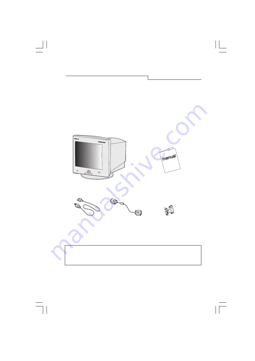
Check following items.  If they are missing or damaged, consult your place of purchase
immediately.

Acer 211c color monitor

User’s manual

Power cord

15-pin D-SUB     Macintosh adapter

 signal cable

(Optional)


?

Locate the model name and the serial number labeled on the back
of your monitor.  Write down the related information of your
monitor and dealer in the space on page iii for future reference.

Unpacking the Package

All manuals and user guides at all-guides.com

all-guides.com

Summary of Contents for 211c

Page 1: ...User s manual Power cord 15 pin D SUB Macintosh adapter signal cable Optional Locate the model name and the serial number labeled on the back of your monitor Write down the related information of your monitor and dealer in the space on page iii for future reference Unpacking the Package All manuals and user guides at all guides com a l l g u i d e s c o m ...

Page 2: ...uration or adjustment is needed when a user changes display mode Low radiation Acer 211c is not only in compliance with MPRII but also meets strictest low radiation regulations of MPRII and TCO 95 Users and Environment Acer 211c is produced by the ISO 14001 certified manufacturer and in compliance with the global environmental labelling scheme TCO 95 which covers not only standards regarding emiss...

Page 3: ...Off Off Ambe Blinking Overide Normal Off Off Green Factory Preset Timings Resolution Vertical Frequency Horizontal Frequency Hz KHz 640 x 400 70 31 47 640 x 480 60 31 47 640 x 480 75 37 50 800 x 600 75 46 88 1024 x 768 75 60 02 1024 x 768 85 68 68 1280 x 1024 75 79 98 1280 x 1024 85 91 15 1600 x 1200 75 93 75 1600 x 1200 85 106 All above timings are non Interlace timings Unpacking the Package All ...

Page 4: ...m the line voltage designation at the rear panel of the monitor before connecting the machine 1 Make sure that the system power is turned off 2 Please refer to the instructions below to connect the signal cable through D SUB or BNC 3 Connect the power cord to the monitor and attach it to power source 4 Turn on the computer and the monitor All manuals and user guides at all guides com ...

Page 5: ...r Connecting through D SUB signal connector 1 Make sure that the system power is turned off 2 Connect the computer end of the D SUB cable to the 15 pin output connector on the video board of your computer 3 Connect the monitor end of the D SUB cable to the D SUB receptacle on the back of the monitor Installing the Monitor All manuals and user guides at all guides com ...

Page 6: ...able you need to add the Macintosh adapter to connect the video signal port of your computer and the monitor signal cable Before connecting the adapter please refer to the user s guide of the adapter to set the switches of the adapter All manuals and user guides at all guides com a l l g u i d e s c o m ...

Page 7: ... that the system power is turned off 2 Connect the computer end of the BNC cable to the output connector on the video board of your computer 3 Connect the monitor end of the BNC cable to the BNC receptacle on the back of the monitor All manuals and user guides at all guides com ...

Page 8: ... auto save or leaves OSD l key scrolls the light coloured bar up or down and represents HOT KEY for brightness adjustment l key scrolls the light coloured bar left or right and represents HOT KEY for contrast adjustment l i key is used for Fuzzy Automatic calibration adjustment Chapter 3 A Look at the Control Panel All manuals and user guides at all guides com ...

Page 9: ...ay mode The i key function is different from Reset function Reset function for display s geometry size and position only works under the factory preset timings please see page 3 The i key function will work under ANY display timings which Acer 211c can support Hot Keys Press or key to adjust contrast directly Press or key to adjust brightness directly A Look at the Control Panel All manuals and us...

Page 10: ...s Press or keys to scroll light coloured bar to desired items Then press or key to adjust as required 5 Press Exit key to save and return to main menus 6 Press Exit key to save and leave OSD Reset to the factory default settings please see General Settings Reset and Color Temperature Reset Main Menu 1 Display Control This main menu includes six items Scroll the light coloured bar to desired items ...

Page 11: ...nd dark areas Brightness adjusts the brightness of the display Size Position Display size and position adjustment Luminance Contrast and Brightness adjustments A Look at the Control Panel All manuals and user guides at all guides com a l l g u i d e s c o m ...

Page 12: ...n controls the straightness of the vertical edges of the display Unbalance adjusts balance when the sides of display are bowed towards left or right Trapezoid makes the vertical edges of the display parallel Parallelogram corrects image leaning left or right Rotation corrects screen tilt Top Corner adjusts the edges on the top corners of the screen image Bottom Corner adjusts the edges on the bott...

Page 13: ...uced by magnetism press Enter to active Degauss function Reset to Default Reset the monitor to the default factory settings including H V position H V size Pincushion Unbalance Trapezoid Parallelogram Rotation Corner H VConvergence H V Moire and Moire For preset timings in order to reset to factory default values press Enter To reset color Temperature plsease see page 15 A Look at the Control Pane...

Page 14: ...an also be modified by user The preset informa tion as follows Factory Default Color Temperature C1 9300K C2 6500K C3 5500K C4 7100K C5 1 1500K Scroll the light coloured bar to desired color temperature then press Exit to save the setting and leave OSD Press Enter key to sub menus and adjust RGB color weight All manuals and user guides at all guides com ...

Page 15: ...key to do the adjustments To reset to factory default values scroll light coloured bar to item Reset to Default Main Menu 3 Advanced Display Control This main menu includes six items scroll light coloured bar to desired items Press Enter key to enter sub menus A Look at the Control Panel All manuals and user guides at all guides com ...

Page 16: ... best to have an image that makes it easy to see any convergence error A black background with white letters or lines is recommended When adjusting convergence look at the adjustment across the whole screen When adjusting horizontal convergence look at the left and right edges of vertical lines or characters When adjusting vertical convergence look at the top and bottom edges of horizontal lines o...

Page 17: ...r every other dot pattern Moire cannot be eliminated However it can be re duced with the moire reduction feature Moire can be reduced by adjusting the iscreen moire reduction function Prior to adjustment set the screen to a full white pattern so that moire will be visible After this adjustment make changes to a different screen background in order to reduce moire even further If the picture is uns...

Page 18: ...r select There are two kinds of input connectors for Acer 211c One is a BNC connector the other is a DB 15 The Acer 211c is capable of automatically detecting the type of connector used either BNC or DB 15 If the two con nectors are connected simultaneously the user can select the desired connector All manuals and user guides at all guides com ...

Page 19: ...ose a full white picture and adjust to get a pure white picture at the corner of the screen image Display Mode Current resolution horizontal and vertical frequency status presentation A Look at the Control Panel All manuals and user guides at all guides com ...

Page 20: ...KHz However due to different video card and resolution settings we recommend that you do not exceed the maxi mum refresh rate 160 Hz for vertical frequency and 107KHz for horizontal frequency to avoid possible damage to your monitor Resolution Recommended Maximum Vertical Refresh Rate Hz 640 x 480 160 800 x 600 145 1024 x 768 135 1280 x 1024 100 1600 x 1200 90 To set the timing and the refresh rat...

Page 21: ...ND G GND 8 B GND B GND B GND 9 PC5V For DDC PC5V For DDC PC5V For DDC 10 GND SYNC GND SYNC GND SYNC 11 GND GND GND 12 DDC Data DDC Data DDC Data 13 H SYNC H V SYNC Not Used 14 V SYNC Not Used Not Used 15 DDC Clock DDC Clock DDC Clock Pin Assignments D SUB Connectors A Look at the Control Panel All manuals and user guides at all guides com a l l g u i d e s c o m ...

Page 22: ... Assignment separate composite sync on green B Blue Blue Blue G SYNC Green Green Green SYNC R Red Red Red H H V H SYNC H V SYNC NC V V SYNC NC NC Chapter 3 BNC Connectors All manuals and user guides at all guides com ...

Page 23: ...deo sync signal must be specified for the monitor l Power saving mode Press any key and use the mouse to deactivate the mode l Signal cable connector pins If pins are bent or missing consult your dealer If the picture is scrolling or unstable check l Signal connector pin assignments Replace with a functional one if inoperative l Signal cable connector pins If pins are bent or missing consult your ...

Page 24: ... on the monitor Do not attempt to open the monitor You may be hurt by electric shock For service call your dealer Do not use your monitor when magnets or electronic products are operating nearby Do not use harsh chemicals or strong cleaning solvents to clean the monitor screen Wipe it with mild solution applied on clean and soft cloth Do not place anything on your monitor Bad ventilation may eleva...

Page 25: ...ower consumption 150 Watts max 165 Watts max With USB External Controls Powerswitch ikeyauto calibration Contrast Brightness Horizontal Position Horizontal Size Vertical Position Vertical Size Pincushion Unbalance Trapezoid Parallelogram Rotation Top Corner Bottom Corner Color Weight Degaussing Horizontal Convergence Vertical Convergence Horizontal Moire Vertical Moire BNC and DB 15 Selection Rese...

Page 26: ...Temperature Operating 5C 40C Storage 0C 60C Humidity Operating 20 90 Storage 10 90 X Radiation DHHS PTB Regulatory Compliance FCC B UL FTZ B CSA BZT B CE D N S F TÜV GS Ergonomics VCCI ISO 9241 3 ISO 9241 8 CNS 13438 C tick MPR II TCO95 All manuals and user guides at all guides com a l l g u i d e s c o m ...

Reviews: