background image


A B B   M E A SURE M E N T  &  A N A LYT I CS  | STA RT UP  GUI DE  

XSeries

G5

 Flow Computers and  

Remote Controllers 

XFC

G5

 and XRC

G5


Scalable 

measurement 

control for 

production 


Measurement 

made easy 


Introduction 

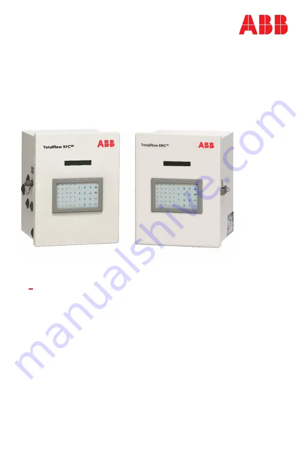
This startup guide provides basic installation and configuration procedures 

for the XFC

G5

 and XRC

G5

. It is designed for typical installations only, 

performed by personnel knowledgeable of:  


Flow computers and remote controllers


Local and national codes as they apply to hazardous areas


Communication and electrical wiring


Use this guide in conjunction with other drawings and documentation that 

may accompany the product purchase order. Many sites have unique 

installation requirements. In these cases, it is important to reference site-

specific documentation.


Summary of Contents for X Series G5

Page 1: ...XFCG5 and XRCG5 It is designed for typical installations only performed by personnel knowledgeable of Flow computers and remote controllers Local and national codes as they apply to hazardous areas Communication and electrical wiring Use this guide in conjunction with other drawings and documentation that may accompany the product purchase order Many sites have unique installation requirements In ...

Page 2: ......

Page 3: ...tery and charger requirements 10 External power supply requirements 10 Location specification and design 10 Wiring requirements 11 2 Basic hardware installation 12 Required tools and materials 12 Unpack and inspect 13 Pipe mount installation 14 Wall mount installation 15 Direct mount installation 16 Ground equipment 18 Leak test manifold and tubing connections 18 Install and connect the RTD for th...

Page 4: ...cation with the device 46 Set up PCCU for connection 46 Establish connection with the XFC or XRC 47 Change to Expert view 49 8 Configure the basic parameters 50 Station parameters 50 Change the default time and date format 51 9 Initial measurement application setup 52 10 Configure communications 55 Configure COMM1 55 Configure COMM2 58 Configure for network communication 59 Enable and configure Et...

Page 5: ...LCD visual alarm and status codes 72 Failure to start 74 The screen has locked up 74 Remote communication failure 75 Contact us 77 ...

Page 6: ...its system and interfaces against any kind of security breaches unauthorized access interference intrusion leakage and or theft of data or information ABB Inc and affiliates are not liable for damages and or losses related to such security breaches unauthorized access interference intrusion leakage and or theft of data or information Although ABB provides functionality testing on the products and ...

Page 7: ...lable for download at www abb com upstream Related documents Document number XSeriesG5 User Manual 2106026 XSeriesG5 Board Replacement Kit Guide 2106079 TFIO Module User Manual 2101226 Wi Fi antenna kit installation guide 2106123 User Drawings XFCG5 Generic Pinout 2106114 XRCG5 Generic Pinout 2106113 ...

Page 8: ... is for electrical danger the exclamation point is for general dangers DANGER Serious damage to health risk to life This symbol and the signal word DANGER indicate imminent danger or explosive hazard Failure to observe this safety information will result in death or severe injury The text may state the hazard how to avoid the hazard and the result if not followed WARNING Bodily injury These symbol...

Page 9: ...ized personnel should work in hazardous locations There are no chemical or burn hazards Personal Protection Equipment is not required WARNING Bodily injury Apply power only after the procedures are complete Technicians must perform the procedures in order plan install wire verify the power on sequence and configure WARNING Bodily injury Read and follow instructions contained in this guide before a...

Page 10: ...ent WEEE marked using the crossed out wheeled bin symbol shall not be mixed with general household waste Correct disposal at a recycling facility will help save valuable resources and prevent potential negative effects on health and the environment These steps ensure compliance with the WEEE Directive FCC RF Compliance ...

Page 11: ... RTD Solar panel charger and mounting kit If the standard configuration differs from the specific site needs and is not addressed in this guide see the user manuals listed in Additional information This guide assumes an orifice plate as the meter element The XFC and XRC support other meter types For XRC illustrations see the user manual listed in Additional information Application credits Standard...

Page 12: ...tertight corrosion resistant seal between the outside elements and the components It is rated NEMA TYPE 3R or IP54 Plan the installation based on enclosure dimensions and battery weight per model See the user manual listed in section Additional information for more complete dimensions and specifications Battery and charger requirements 12 Vdc sealed lead acid battery Size is dependent on the devic...

Page 13: ... wiring must be complete before the device is energized See section 6 Powering the device Wiring requirements All onboard screw terminal connectors support a wire gauge range of 12 AWG to 22 AWG Select the wire gauge compliant with the local electrical code for the type of signal on the connection voltage and current load and wire length WARNING Bodily injury Area classification requirements deter...

Page 14: ...ded if mounting a solar panel See Figure 3 1 Solar panel EFM plus bolts and washers 5 valve manifold 2 stabilizers futbols plus bolts and washers Wall mount installation One 1 enclosure mounting kit includes instructions brackets U bolts and fastening hardware Four 4 wall fasteners length and girth determined by technician based on wall thickness and materials EFM plus bolts and washers 5 valve ma...

Page 15: ...dditional parts ship in a specially designed shipping carton with a startup guide and packing list IMPORTANT NOTE Inspect the contents for damage before discarding the shipping and packing materials Unpack the XFC or XRC and inspect for damaged missing or incorrect parts 1 Inspect the shipping carton for damage 2 Carefully remove items from the carton 3 Keep all shipping materials to return any da...

Page 16: ...pipe saddle with mounting hardware size determined by technician One 1 2 inch x 40 inch pipe length may be extended if mounting a solar panel See Figure 3 1 Solar panel Pipe mount the XFC XRC is similar 1 Position the pipe saddle on the meter run and temporarily attach the saddle to the meter run pipe using the associated hardware Figure 2 1 Mounting pipe Legend Mounting pipe 1 Meter run 3 Saddle ...

Page 17: ...responding holes on the upper mounting bracket b Add the flat washer and split washer onto the U bolt then screw the nut onto the U bolt c Repeat steps 6a and 6b for the second mounting bracket 7 Raise the XFC or XRC into position on the mounting pipe IMPORTANT NOTE Position the XFC or XRC high enough to allow some downward slope from the externally mounted manifold to the tap valves 8 Secure the ...

Page 18: ... wall stud or wall support of sufficient strength to support the weight of the XFC or XRC 2 Install the XFC or XRC mounting brackets on the back of the enclosure using the pipe mount instructions supplied with the mounting kit 3 Determine the appropriate mounting height for the XFC or XRC to allow some downward slope from the XIMV and manifold to the meter run tap valves This allows condensate to ...

Page 19: ...rifice tap valves and the manifold 4 Install the nut and ferrule onto the tubing end NOTICE Equipment damage To avoid damage to the stainless steel tubing fittings and valves always use a backup wrench to stabilize and eliminate tension on both sides of the connection when tightening Damaged connections may introduce leaks into the system resulting in inaccurate measurement 5 Insert the ferrule in...

Page 20: ...is located on the bottom front of the XFC or XRC enclosure NOTICE Equipment damage or loss of data The grounding conductor must have a cross sectional area of at least 12 AWG or 4 mm2 Leak test manifold and tubing connections Install input lines and manifold The following procedure provides a generalized guideline to follow for the manifold and tubing installation Materials 1 Stainless steel tubin...

Page 21: ...g Damaged connections may introduce leaks into the system resulting in inaccurate measurement 5 Insert the ferrule into the fitting and slide the nut onto the ferrule engage the nut threads and tighten 6 Repeat step 5 for each tubing connection point Manifold and tubing connections must be leak tested before power application Connection leaks between the tap valves the orifice the manifold and the...

Page 22: ... following connections High and low pressure tap valve connections High and low pressure manifold tubing connections Connection points between the flange and the manifold Bubbles in the liquid indicate a loose or poor connection 5 Use a wrench to tighten connections and recheck NOTICE Equipment damage Do not over tighten the connections After verification that all connections are leak free proceed...

Page 23: ... national and local codes Materials RTD probe with cable and cable gland installed probe and cable length determined by technician Nylon tie wraps Install the RTD probe 1 Insert the RTD probe into the thermowell to determine the depth setting for the probe spring Figure 2 4 Typical RTD installation 2 Use snap ring pliers to adjust the retaining ring below the spring on the probe Probe depth should...

Page 24: ...se nylon tie wraps to secure the cable to the pipeline 4 Install the RTD cable into the flow computer enclosure a Remove the shipping plug from the right side of the flow computer enclosure b Remove the cable nut from the gland and insert the RTD cable end through the access hole in the enclosure Leave enough cable inside the enclosure to accommodate wiring to the RTD terminal block J7 c Replace t...

Page 25: ... terminal connector from the J7 terminal block 3 On the RTD probe wire remove the spade lugs if installed and trim the wire cover ends back inch 6 35 mm 4 Loosen the screws on the terminal connector for pins 1 through 5 IMPORTANT NOTE If the shield is not shorted to the probe insert the shield wire to pin 1 Do not connect if the shield wire is shorted to the probe 5 Insert the corresponding wires ...

Page 26: ...T NOTE The XSeries Wi Fi Kit is required for antenna installation See Additional information 1 Install the antenna to support onboard Bluetooth and Wi Fi wireless interfaces 2 Use the onboard connector ANT 1 J42 to connect the antenna 3 Use the cap to isolate the unused antenna connector ANT 2 ...

Page 27: ...ection 11 Powering the device Install the battery The battery mounts inside the flow computer enclosure Before installation inspect the power cables where they terminate on the battery and the connectors for damage Material One 1 battery with cable attached Install the battery 1 Open the hinged door on the XFC or XRC Locate the battery shelf 2 Place the battery on the compartment shelf do not allo...

Page 28: ...r panel on the top or side of a meter house call the main office listed on the back cover of this guide and select technical support from the menu options Materials One 1 solar panel with cable One 1 solar panel mounting kit includes U bolts brackets and hardware Mounting pipe extension and coupling if required length determined by technician depending on the size of the solar panel Nylon tie wrap...

Page 29: ...the solar panel mounting bracket to the top end of the mounting pipe with the U bolts and associated mounting hardware Do not tighten completely Figure 3 1 Solar panel Legend Solar panel 1 Pipe coupling 4 Solar mounting bracket 2 Extension pipe 5 Solar panel cable 3 U bolts 6 Flow computer 5 In the northern hemisphere position the solar panel facing south In the southern hemisphere position the so...

Page 30: ...access hole in the enclosure d Pull the cable into the enclosure leaving enough cable to reach the CHRG terminal block J5 on the XFC J17 on the XRC e Replace the cable nut on the cord and conduit end inside of the enclosure and screw the nut onto the conduit end finger tight f Position the conduit elbow so that moisture will not follow the cable and seep into the gland Tighten the cable nut g Usin...

Page 31: ...block on the XFC NOTICE Equipment damage Do not over tighten the terminal connector screws as this may damage the wires NOTICE Equipment damage Do not connect the solar panel to the electronic board before battery connection Damage to the board will void any warranty ...

Page 32: ...1220 meters NOTICE Equipment damage External devices can be powered from the VBAT or SW VBAT pins on the XFC or XRC COMM ports The output voltage at these pins is dependent upon the external power supply connected to the CHRG connector J5 on XFC J17 on XRC The voltage range at J5 or J17 can be from 9 Vdc to 15 5 Vdc The XFC and XRC are 12 Vdc nominal powered devices Before connecting an external d...

Page 33: ...ure 4 1 XFC R 232 COMM1 IMPORTANT NOTE Typically only TXD RXD and GND may be required to communicate with a third party RS 232 device The figure above illustrates all lines associated with COMM 1 or COMM2 RS 232 module Figure 4 2 XFC R 232 COMM2 ...

Page 34: ...4 TXD 5 6 RXD 7 8 RTS 9 CTS 10 DTR 11 DCD 12 TXD 13 RXD 14 RTS 15 CTS 16 OPERATE OPERATE Blank cells carry no signal IMPORTANT NOTE Figure 4 3 COMM1 and Figure 4 4 COMM2 show connection lines to a single device RS 485 supports multiple devices per port For additional wiring options search additional user drawings at www abb com upstream Figure 4 3 XFC 485 COMM1 ...

Page 35: ... device The figure above illustrates all lines associated with COMM 1 or COMM2 RS 485 module Figure 4 4 XFC R 485 COMM2 Table 4 3 XFC RS 485 COMM1 and COMM 2 PIN RS 485 COMM 1 RS 485 COMM 2 1 GND GND 2 VBATT VBATT 3 Sw VBATT Sw VBATT 4 BUS 5 BUS 6 BUS 7 BUS 8 RRTS 9 10 11 12 BUS 13 BUS 14 RRTS 15 16 OPERATE OPERATE Blank cells carry no signal ...

Page 36: ... COMM2 See Figure 4 5 RS 232 or Figure 4 6 RS 485 Refer to Table 4 3 for complete pinout for both ports IMPORTANT NOTE When wiring for RS 485 communication set the termination jumpers J7 or J10 in the correct position See details in Table 10 2 COMM1 or Table 10 3 COMM2 Figure 4 5 XRC RS 232 COMM 1 IMPORTANT NOTE Typically only TXD RXD and GND may be required to communicate with a third party RS 23...

Page 37: ...UP GUIDE 35 Figure 4 6 XRC RS 485 COMM 1 Table 4 4 XRC COMM 1 and COMM 2 pinouts PIN RS 232 COMM 1 and 2 RS 485 COMM 1 and 2 1 VBATT VBATT 2 GND GND 3 SW VBATT SW VBATT 4 OPER OPER 5 RTS RRTS 6 DCD BUS 7 RXD BUS 8 CTS BUS 9 TXD BUS ...

Page 38: ...connected to the CHRG connector J5 on XFC J17 on XRC The voltage range at J5 or J17 can be from 9 Vdc to 15 5 Vdc The XFC and XRC are 12 Vdc nominal powered devices Before connecting an external device to VBAT or SW BAT ensure that the device is compatible with this voltage range Connecting an incompatible device may result in damage to the device Analog input AI pinouts The XFC has two onboard an...

Page 39: ...jumpers Use these jumpers to set the analog input for the type of input signal expected voltage or current Follow the legend to set the correct AI to the correct mode By default all analog inputs are set for voltage inputs 0 10 V Figure 5 2 XRC AI terminals and input mode selector jumpers Table 5 2 XRC AI Pinouts Input Pin Description AI 1 1 Input signal 2 COM Input ground AI 2 3 Input signal 4 CO...

Page 40: ...ort standard pulse inputs STD or pulse inputs from Coriolis IEC Remember to set the switch to the correct position based on the type of pulse input signal expected Use S3 for DI PI 1 or S4 for DI PI 2 Listed below are the DIs and DOs for the XFC and the XRC Figure 5 3 XFC DI PI DO terminals and input mode switches Table 5 3 XFC DI PI DO pinouts I O Pin J6 Description DI2 PI2 1 Input signal 2 Input...

Page 41: ...e jumpers The input mode switches support standard pulse inputs STD or pulse inputs from Coriolis IEC Remember to set the switch to the correct position based on the pulse input signal expected Use S3 for DI PI 1 S4 for DI PI 2 S7 for DI PI 3 and S8 for DI PI 4 By default the debounce jumpers are set to enable debounce on the DI PI Figure 5 4 XRC DI PI DO terminals input mode switches and debounce...

Page 42: ...le 5 4 XRC DI PI DO Pinouts I O Pin J8 A Description I O Pin J8 B Description DO1 1 Signal DO3 1 Signal 2 GND 2 GND DO2 3 Signal DO4 3 Signal 4 GND 4 GND DI1 PI1 5 Signal DI3 PI3 5 Signal 6 GND 6 GND DI2 PI2 7 Signal DI4 PI4 7 Signal 8 GND 8 GND ...

Page 43: ...llow 2 minutes to charge the super CAP the first time you connect the unit to power The Super CAP must recharge if the XFC or XRC is powered off for several hours After the capacitor is fully charged the boot time is considerably less IMPORTANT NOTE In the event of a loss of power or reset the charged super capacitor prevents the supply voltage from falling to zero for a short period of time 2 5 s...

Page 44: ...ger to recharge the battery This mode requires connection of the battery and the charger The battery and charger must be installed See section 3 Install battery and charger Adapt these instructions for alternate installations Connect the battery dc power Connect the 12 volt SLA battery using the battery cable WARNING Bodily injury and property damage Complete all wiring of peripheral or external d...

Page 45: ...see details in Section 6 1 Super capacitor charging at boot time 3 If the power on sequence fails to initiate or complete press the reset button shown below Figure 6 3 Reset button and coldboot button Connect the charger NOTICE Equipment damage Always connect the battery to the BATT port before connecting the solar panel or alternate charger cable to the XFC or XRC Connect the solar panel charger ...

Page 46: ...de Wire or connect an external power supply to the XFC or XRC 1 Review the manufacturer s instruction supplied with the external power supply 2 Wire or connect the external power supply cable to the BATT connector as shown below Observe the polarity and Figure 6 5 Connect the external power supply 3 Confirm that the XFC or XRC is receiving power by observing the power on sequence information scrol...

Page 47: ...battery does not back up the real time clock The real time clock will continue to operate for 24 36 hours under typical conditions The real time clock will stop operation and lose time without power At the next startup the system will restore the last known good time which can be one of the following a Last Totalflow Running Time Last time Totalflow was running or when the power was lost This is t...

Page 48: ...ctions see the user manuals listed in Additional information IMPORTANT NOTE PCCU32 has context sensitive online help Click Help on the screen of interest to view the topic applicable to the screen IMPORTANT NOTE Local communication using Ethernet Bluetooth or Wi Fi are all supported on the XFC and XRC but these interfaces must be enabled first See section 10 3 Configure for network communication S...

Page 49: ...ART UP GUIDE 47 Figure 7 1 System Setup 4 Click Close Establish connection with the XFC or XRC Connect to the device entry mode 1 On the PCCU32 tool bar click Entry to connect to the device Figure 7 2 PCCU32 Tool bar and Entry ...

Page 50: ... s a message box displays with the option to synchronize the date and time Figure 7 3 PCCU32 Date Time synchronization warning IMPORTANT NOTE Click Help for more information 3 Click No to set the time and date later during the installation or click Yes to synchronize date and time When successfully connected to the XFC or XRC the screen displays the device and measurement variables ...

Page 51: ...nd advanced configuration Change the view while connected to the XFC or XRC 1 While connected to the XFC or XRC Entry mode on the top PCCU32 menu bar select View 2 Select the Expert option Figure 7 5 PCCU32 Views 3 Click Yes at the warning notice and wait for the PCCU32 Entry mode screen to refresh 4 Wait for the Entry mode screen to reappear ...

Page 52: ... parameters Configure basic station parameters 1 At the PCCU32 Entry screen click the station ID TOTALFLOW at the top of the navigation tree The Station Setup tab displays Figure 8 1 Station Setup 2 Set up the basic station configuration parameters identified in the following table ...

Page 53: ...instantiated 1 Verify the Lithium Battery Status is OK with a green bar see Figure 8 1 Station Setup If the status is Low Voltage or Not Connected the field background color is red 2 Change settings in the Station Setup tab as needed Leave PCCU open on the Station Setup tab For more information refer to the XFC or XRC user manual Change the default time and date format The factory configuration ha...

Page 54: ... the specific application required Set up the gas orifice flow measurement application 1 On the PCCU navigation tree click Flow Measurement Adv Setup Figure 9 1 Flow Measurement Advanced Setup Gas orifice 2 On the Setup tab verify and change if necessary the following settings a If receiving live flowing temperature values from an RTD set the RTD Installed field to Yes b If using a fixed temperatu...

Page 55: ...alculation Type field select the calculation standard for this tube b In the Fpv Method field select the compressibility method for this tube Figure 9 2 Flow measurement setup General tab 5 Click Send 6 Select the Constants tab Figure 9 3 Constants Tab ...

Page 56: ... the contracted value b For Orifice diameter type the diameter in inches c For Pipe diameter type the pipe diameter in inches d For Temperature base Tb type the value as defined by the existing contractual agreement default is 60 F 8 Click Send 9 Continue to the other tabs for additional configuration if needed IMPORTANT NOTE The previous steps are the minimum requirements to get a Totalflow XFC o...

Page 57: ...M1 configured for remote communications with a host The port TF Remote COM1 is configured to support the Totalflow Remote Protocol by default For additional details click Help from the Communications Setup tab screen for details Configure COMM1 1 Install the communication module for the required serial interface type RS 232 or RS 485 in the COMM1 slot on the XFC or XRC board Figure 10 1 XFC COMM t...

Page 58: ...elect the communication interface RS 232 RS 485 or RS 232 Modem 7 Verify and change if necessary the remaining serial port settings and timeouts and delays Table 10 1 Communication setup parameters Timeouts and delays Serial port settings Parameter Default Parameter Default Ack timeout s 15 Baud 9600 Response delay ms 40 Parity None Xmit key delay ms 420 Data bits 8 Unkey delay ms 40 Stop bits 1 P...

Page 59: ...E The symbol flashes according to the Listen Cycle defined for the communication port The default Listen Cycle is 4 If set to zero the symbol should be displayed continuously See the PCCU32 Help files for communication port setup to learn how this setting effects power usage 11 To set up and schedule the remote communication port for power conservation a Select TF Remote COM1 on the navigation tre...

Page 60: ...unications Setup tab screen and configure the port as required by the external device Configure COMM2 1 Install the communication module for the required serial interface type RS 232 or RS 485 in the COMM2 slot on the XFC or XRC board 2 Wire the communication equipment according to the type of serial interface required See section 4 Wire COMM ports 3 On the PCCU navigation tree click Communication...

Page 61: ...s networks The Ethernet port supports connection for both local and remote communication The Wi Fi and onboard Bluetooth wireless interfaces support connection for local wireless communication This procedure enables the device Network ID which is required before enabling Ethernet Wi Fi or Bluetooth communication the same Network ID applies to all three types of connections IMPORTANT NOTE The Netwo...

Page 62: ...configuring the address manually obtain a valid IP address from the IT administrator For additional details click Help from the Ethernet tab screen Configure the Ethernet interface 1 Configure Network ID 2 Connect the Ethernet cable from the XFC or XRC to the network communication equipment hub switch router etc 3 On the PCCU Entry mode navigation tree select Communications 4 Select the Ethernet t...

Page 63: ...he parameters from the DHCP server i Ensure that the connection to the corporate network is active and verify that the DHCP server is running and available ii If unable to connect to the DHCP server contact the IT administrator 9 Ping the IP address of the device from the corporate network or local switch and verify that the device replies IMPORTANT NOTE To restart or reinitialize the Ethernet int...

Page 64: ...XFC or XRC enabled as a Wi Fi Access Point does not provide bridging or routing between the wireless Wi Fi and the wired Ethernet networks Enable as a Wi Fi Access Point 1 Install the antenna See 2 10 Install antenna 2 Configure the Network ID 3 On the PCCU Entry mode navigation tree select Communications 4 Select the Wi Fi tab Figure 10 7 Wi Fi tab screen 5 Select the Enable Wi Fi Access Point ch...

Page 65: ...e IP address default 192 168 1 1 as it is required to establish connection using PCCU IMPORTANT NOTE The default IP address assigned to the XFC and XRC for Wi Fi connections is not the same as the default IP address assigned to Ethernet When configuring PCCU for either type of connection make sure to use the correct address 11 Test that the Wi Fi enabled XFC or XRC is available and establish conne...

Page 66: ...192 168 1 1 e Click Close to exit PCCU setup and return to the main PCCU screen f On the PCCU toolbar click Entry and verify connection is established Enable Bluetooth The XFC and XRC support Bluetooth functionality to allow wireless local access This procedure enables onboard Bluetooth For additional details or if using a USB dongle click Help from the Bluetooth tab screen or refer to the user ma...

Page 67: ...e 10 9 Enable Bluetooth 9 Select the Communication Setup tab The Bluetooth port displays as unused in the port list Figure 10 10 Communication Setup for Bluetooth 10 Select Bluetooth Unused 11 Select Add New Device Application See the figure below ...

Page 68: ...n Setup tab verify that the port list and the description both display Bluetooth See the figure below Figure 10 12 Verify Bluetooth application assignment 16 Start a new instance of PCCU to test the Bluetooth connection or close the current connection a Start PCCU from the top menu and select Setup b Under Communications PCCU Connect method select Bluetooth c Select Search for Bluetooth devices ...

Page 69: ...the device on the list and highlight f Click Select Figure 10 13 PCCU Connection Setup for Bluetooth 17 Click Close to exit PCCU connection setup 18 On the top PCCU menu click the Entry icon to connect to the XFC or XRC 19 When the connection is successful continue with configuration procedures or click Close to close the Bluetooth connection 20 For further configuration or changes to the Bluetoot...

Page 70: ...d connection to the XFC or XRC is restricted to users with the correct security codes This procedure requires opening the enclosure to access to the XFC or XRC board Configure the security settings 1 Open the XFC or XRC enclosure door and locate the onboard security switch S1 See the figure below Figure 11 1 S1 Security switch Legend S1 Security switch 1 Battery 2 Security switch 2 Ensure the secu...

Page 71: ...vel 2 read and write access IMPORTANT NOTE Record the security codes Once saved they are not visible on the Station Setup tab 6 Click Send 7 On the board set the XFC or XRC security switch to ON 8 On the Station Setup tab click Re read and check that the security switch status is On Enforcement of the security codes is in effect IMPORTANT NOTE The codes will be required the next time PCCU32 attemp...

Page 72: ...ation and Preserve device data and configuration sections in the user manual See Additional information Validate measurement 1 Perform static pressure SP and differential pressure DP calibration pressure checks 2 If it is necessary to correct errors in the measurement system proceed to the calibration instructions in the user manual Place the device in service The following instructions provide ge...

Page 73: ...eam tap valves items 2 and 4 to open the process stream creating flow 5 Wait until the system has pressurized typically less than 1 minute before continuing 6 Close the equalization valves items 1 and 3 on the manifold Optional volume reset recommended This procedure allows the device to have an official starting point for valid live data The Events file keeps the record of the volume reset and ti...

Page 74: ...onal information LCD visual alarm and status codes The LCD displays alarm conditions and status codes in the Annunciator area see Figure 13 1 XSeriesG5 annunciators IMPORTANT NOTE Alarms are recorded in the Log period flow record Status codes are not recorded in the Log period flow record Figure 13 1 XSeriesG5 annunciators The following table lists the indicator symbol and description of the statu...

Page 75: ...n the baud rate is faster than 2400 then the flashing symbol may not be visible The annunciator will remain on listening cycle if the listen cycle is set to zero M MODBUS ASCII MODBUS ASCII protocol is selected for the port assigned to this annunciator m MODBUS RTU MODBUS RTU protocol is selected for the port assigned to this annunciator L Local Protocol Displayed when the PCCU32 port is active an...

Page 76: ... capacitor charging at boot time The display should begin cycling though the pre programmed items If it fails to cycle and locks up follow the procedure below IMPORTANT NOTE Display time for screens 1 through 4 will vary If the startup cycle stops record the details on the screen Provide the screen details to technical support to help them resolve the issue The screen has locked up Follow this pro...

Page 77: ...ion Use the following list to eliminate possible remote communications issues in any order 1 Verify that the symbol flashes in the A8 display position see Figure 13 1 XSeriesG5 annunciators This indicates that the port is actively running Totalflow Remote Protocol Each flash identifies the Listen Cycle time period a If the symbol is not flashing i Set the port Listen Cycle to zero The symbol shoul...

Page 78: ...lly WinCCU a The Station ID and the Device ID match the host settings b No other device is using the same Station ID or Device ID c The baud rate stop bits security code and listen cycle time agree between the host WinCCU device and flow computer d The host WinCCU is using packet protocol More information about identifying and correcting radio communication issues is available in the Communication...

Page 79: ...ield 4300 Stine Road Suite 405 407 Bakersfield CA 93313 Ph 1 661 833 2030 Texas Office Pleasanton 150 Eagle Ford Road Pleasanton TX 78064 Ph 1 830 569 8062 We reserve the right to make technical changes or modify the contents of this document without prior notice With regard to purchase orders the agreed particulars shall prevail ABB does not accept any responsibility whatsoever for potential erro...

Reviews: