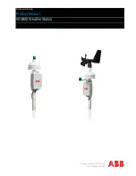
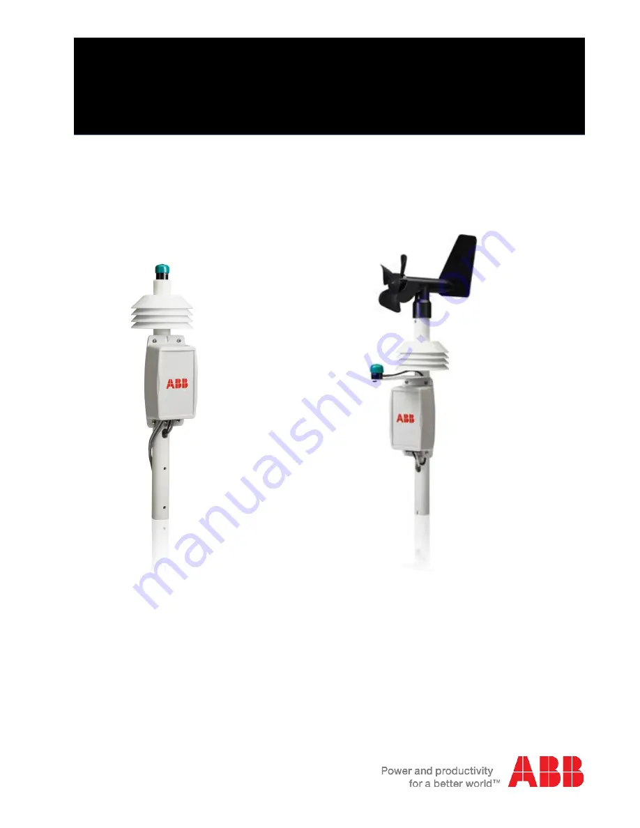
background image

Solar monitoring 

Product Manual 

VSN800 Weather Station 


Summary of Contents for VSN800

Page 1: ...Solar monitoring Product Manual VSN800 Weather Station ...

Page 2: ...ion to the management system using the Modbus protocol The weather station is powered via 24VDC power which is typically available from the data collection hardware of the management system Once the hardware is installed you will need to login to the management system website to verify the Internet is connected properly and verify that the data in being received The VSN800 Weather Station is SunSp...

Page 3: ...y VSN800 Weather Station which includes Pyranometer Ambient Temperature Sensor External PV Panel Temperature Sensor External Second Pyranometer VSN800 14 Model Only Wind Speed and Wind Direction Sensor VSN800 14 Model Only Mounting Hardware Tripod or pole mount base Guy wire kit if necessary 24VDC Power Twisted Pair Wires Site selection and mounting Weather station location The ideal site is level...

Page 4: ...ort structure using U Bolts Do not tighten the support structure to the unit as directional orientation will be required Rotate the assembled unit until the electronics enclosure faces TRUE SOUTH or TRUE NORTH if you are in the northern or southern hemisphere respectively Secure the support mast to the assembly Lining up the two holes in each mast prevents rotation At this point the entire unit sh...

Page 5: ...sure to remove the protective green cap from all pyranometers so they can measure insolation Plane of Array Irradiance VSN800 14 Model Only The plane of array pyranometer is mounted on the side of the solar array The sensor should be at the same zenith and azimuth angle as solar array to correctly measure the plane of array irradiance Anemometer VSN800 14 Model Only The anemometer is directly atta...

Page 6: ...tion and the SunSpec compliant management system is 1000 m 3000 ft High voltage areas of power plants are electrically noisy environments so shielded cable is advised for connection from the weather station to RS485 If outdoor exposure or proximity to a noise source is a concern Beldon 1120A or equivalent cabling should be used Cables to external sensors are supplied with the sensor Wiring instruc...

Page 7: ...he VSN800 14 model if you are in the southern hemisphere the jumper at J11 must be set to Southern If you are in the northern hemisphere no adjustment is required J11 is located in upper left section of the circuit board Connect to the monitoring or management system The Modbus RS485 connection is same as with any other RS485 device connected to a SunSpec compliant management system Refer to your ...

Page 8: ...485 termination VSN800 14 VSN800 12 Weather Station Electronics Board Jumper for RS485 Termination The default address of the weather station is 60 Contact Customer Support if it is required to change the address You cannot have two weather stations in the same RS 485 chain unless the address of one of the weather stations is changed RS485 Terminals Terminal Label RS485 Signal RS485 A Negative RS4...

Page 9: ... C_DeviceAddress unint16 N A N A 60 Modbus Id SunSpec Device Model Measurement Registers 0070 0070 1 C_SunSpec_DID int16 N A N A 307 Start of next Device 0071 0071 1 C_SunSpec_Length int16 N A N A 11 Device Model Block Size 0072 0072 1 E_BaseMet_Air Temperature int16 C 1 Measured Ambient Air Temperature 0073 0073 1 E_BaseMet_Relative Humidity int16 0 N A Relative Humidity 0074 0074 1 E_BaseMet_Bar...

Page 10: ... where n number of sensors blocks 0092 0092 1 E_BOM_Temp_1 int16 C 1 Measured Back of module temperature 0093 0093 1 E_BOM_Temp_2 int16 C 1 Measured Back of module temperature End of Block Registers 0094 0094 1 EndOfSunspecBlock uint16 N A N A 0xFFFF End of SunSpec Block 0095 0095 1 C_Sunspec_Length uint16 N A 0 0 Terminate length zero Device Address Write Register 0200 0200 1 Modbus Id Write Regi...

Page 11: ...sor Terminals Pyranometer 2 Positive Signal Red Ground Negative Signal Black Shield Cable Shield and Drain clear PV Temperature Terminal 1st Sensor PV Temp 1 Signal Black or White PV Temp 1 Signal Black or White Shield Cable Shield and Drain bare Connect PV panel sensor VSN800 12 only If you are not planning to connect the PV panel temperature sensor skip this section 1 Attach the PV panel tempera...

Page 12: ...four screws Make sure not to pinch the newly connected 24VDC or RS485 wires coming out of the case bottom Note that the cover only goes on one way with the opening for wires at the bottom 3 If necessary complete the pole mounting of the weather station Connections to VSN750 series products This section shows how to tap the 24VDC power and make RS485 connections from a VSN750 series management syst...

Page 13: ...installation and system validation The management system must be properly installed and communicating before you can verify that data is flowing form the VSN800 series weather station If you are using VSN800 series in conjunction with Plant Portfolio Manager software go to www auroravision net and log in to Plant Portfolio Manager with your account name and password Using your product license key ...

Page 14: ...d Outdoor Enclosures UL 94 V 2 Polycarbonate Body Pyranometer Sensor RoHS Compliant Body Anodized Aluminum with Cast Acrylic Lens Cable Santoprene Jacket Ambient Air Temperature Sensor RoHS Compliant PV Panel Temperature Sensors RoHS Compliant Body Anodized Aluminum Adhesive Tape Acrylic Titanium Diboride and Aluminum Cable Polyvinyl Chloride Jacket Power and Communications Cable Cable Polyvinyl C...

Page 15: ... 3 C 0 54 F Thermal Time Constant 30 sec PV Panel Temperature Sensor Range 40 to 80 C 40 to 176 F Accuracy 0 3 C 0 54 F Thermal Time Constant 270 sec Cable Length 7 62m 25 ft Anemometer Operational Temperature 40 to 60 C 40 to 140 F Speed Range 0 67 meters per second 150 mph Accuracy Greater of 0 45m sec 1 mph or 5 Threshold 0 89m sec 2 mph Direction Range 360 Resolution 22 5 Accuracy 22 5 Thresho...

Page 16: ...Contact us www abb com solar ...

Reviews: