background image


DISTRIBUTION SOLUTIONS


UniGear Family


UniGear Digital


Commissioning and testing Guide


Summary of Contents for UniGear Digital

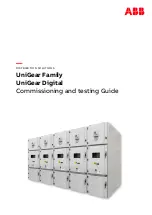
Page 1: ...DISTRIBUTION SOLUTIONS UniGear Family UniGear Digital Commissioning and testing Guide...

Page 2: ......

Page 3: ...DISTRIBUTION SOLUTIONS UniGear Family UniGear Digital Commissioning and testing Guide...

Page 4: ...grams and so on to protect these products the network its system and interfaces against security breaches unauthorized access interference intrusion leakage and or theft of data or information ABB per...

Page 5: ...access to the busbar compartment 23 4 2 4 Non installed busbars in the switchgear panel 26 4 3 Voltage sensors 29 4 3 1 Supervision 29 4 3 2 Voltage sensor installed in the cable compartment 30 4 3 3...

Page 6: ......

Page 7: ...CM600 16 Figure 25 GOOSE SMV alarm is activated on a configurable LED 17 Figure 26 Measurements view voltage receiver protection relay is not synchronized with the Master clock 17 Figure 27 Measuremen...

Page 8: ...scheme of trucks interlock by the busbar earthing truck 47 Figure 70 Logic scheme of trucks interlock by the busbar earthing switch 47 Figure 71 Single line diagram the circuit breaker is in the test...

Page 9: ...on relay s WebHMI 71 Figure 112 Measurements view 71 Figure 113 3 phases test setup for the Megger tester 72 Figure 114 1 phase test setup for the Megger tester 73 Figure 115 Connecting cable with RJ4...

Page 10: ......

Page 11: ...BLES VII List of Tables Table 1 Current metering accuracy 19 Table 2 Zero clamping limits 19 Table 3 Voltage metering accuracy 29 Table 4 Zero clamping limits 29 Table 5 Inter tripping rules for Ith l...

Page 12: ......

Page 13: ...roven testing methods 1 2 Intended users This manual is intended to be used by protection relay test and service engineers The pro tection relay engineer needs to have a thorough knowledge of protecti...

Page 14: ...ponding to implementation of Process bus and GOOSE functionalities and usage of sensors The traditional method of commissioning activity starts with primary injections then continues with protection r...

Page 15: ...red from the power supply 3 1 Protection relays Before starting any secondary testing of the protection relay functions verify if the IP ad dresses the network topology and time synchronization settin...

Page 16: ...the same PTP domain ID PTP precision time protocol On the protection relay LHMI go to Main Menu Configuration Time Synchronisation PTP domain ID PTP domain ID 0 In case of Grandmaster clock Satellite...

Page 17: ...riority 1 128 PTP priority 2 128 Figure 5 PTP priority setting for Slave clock If both Master and Backup master clocks fails the protection relays establish a new primary source for time synchronizati...

Page 18: ...C Figure 6 IEEE 1588 master clock status Check the time synchronization status at other protection relays On the protection relay LHMI go to Main Menu Monitoring IED status Time synchronisation Synch...

Page 19: ...devices which support the AFS finder protocol The next dialogue open by double clicking on the respective switch in AFS finder defines the IP address and net mask Figure 8 Properties dialogue of disc...

Page 20: ...on Check Port setting according to the UniGear Digital Engineering Guide It is recommended to assign a bay to port name according to the project documentation for example Network Overview diagram Inte...

Page 21: ...set a transparent time with Power profile The Ethernet switch then only corrects and forwards the PTP messages and cannot become the PTP master The PTP profile must be enabled on all ports The Peer to...

Page 22: ...tween protection relays should not be sent to the control system SMV should only be sent where required Traffic filtering in managed Ethernet switches can be done via logical separation of the data tr...

Page 23: ...assigned for SCADA is not a member of any VLAN except the native one Figure 16 VLAN Configuration dialogue Check setting of Ingress filtering Ingress filtering must be marked for each port The device...

Page 24: ...ust be filtered out This is ensured by setting Ingress filtering on via the VLAN port dialogue The port on the Ethernet switch connected to SCADA is not a member of any VLAN except the native one to f...

Page 25: ...is no special setting in the Ethernet switch for PRP networks For more details and a network topology overview refer to the UniGear Digital Engineering Guide HSR Check the HSR parameters setting acco...

Page 26: ...ctions Check the interconnection of network components protection relays managed Ethernet switches according to documentation for example the Network Overview Diagram Figure 20 Example of HSR Network...

Page 27: ...ETHERNET NETWORK VER IFICATION INTERCONNECTIONS 1VLG500017 C 15 Figure 22 Example of PRP network overview diagram Figure 23 Interconnection of protection relays into PRP networks...

Page 28: ...0 and protection relay is established a green tick mark is shown next to the protection relay icon Figure 24 Example of Plant Structure in PCM600 Network redundancy Check the availability of voltage m...

Page 29: ...ys if voltage values are not in brackets Brackets indicate an invalid or a questionable measurement due to for example a time synchronization error Figure 26 Measurements view voltage receiver protect...

Page 30: ...ed For pre testing secondary tester with sensor support low voltage output signals is re quired The setting of sensors in the protection relay is described in the UniGear Digital Engineer ing guide 4...

Page 31: ...ent metering is supervised by the CMMXU function Metering ac curacy is stated in Table 1 Table 1 Current metering accuracy Characteristic Value Operation accuracy Depending on the frequency of the mea...

Page 32: ...eters set in the protection relay with sensor rating plates placed on the circuit breaker door Figure 29 Example of a current sensor label On protection relay LHMI go to Main Menu Configuration Analog...

Page 33: ...ipping coil MO from the negative potential of power supply in the low voltage compartment before primary injection to avoid unwanted tripping of the circuit breaker Step 3 5 In the cable compartments...

Page 34: ...ering for the phase and measured current in other phases on the pro tection relay LHMI Measurements view Current must be zero in phases which are not under the primary injection test Figure 32 Measure...

Page 35: ...live parts Step 1 6 Verify the sensor parameters set in the protection relay with the sensor rating plates placed on the circuit breaker door Figure 33 Example of a current sensor label On the protec...

Page 36: ...cable sealing end and the cir cuit breaker compartment to the branch conductor behind the lower shutter of the same phase Figure 35 Test setup for current sensors testing when busbars are not install...

Page 37: ...for the phase and the measured current in other phases on the pro tection relay LHMI Measurements view Current must be zero in all phases which are not under the primary injection test Figure 36 Measu...

Page 38: ...against any other live parts Step 1 7 Verify the sensor parameters set in the protection relay with the sensor rating plates placed on the circuit breaker door Figure 37 Example of a current sensor l...

Page 39: ...ressure relief flap from the busbar compartment to get access for one end of the primary injection test set If Ith limiters are installed make sure they will not trip your circuit breaker for example...

Page 40: ...be zero in phases which are not under the primary injection test Figure 40 Measurements view Io A in Measurements view is a measured value not a calculated one Step 7 7 After testing of all 3 phases...

Page 41: ...ing ac curacy is stated in Table 3 Table 3 Voltage metering accuracy Characteristic Value Operation accuracy Depending on the frequency of the measured voltage fn 2 Hz 0 5 or 0 002 Un at voltages in r...

Page 42: ...e star connection Amplitude Corr A sensor rating plate phase A Amplitude Corr B sensor rating plate phase B Amplitude Corr C sensor rating plate phase C Division ration 10 000 Voltage input type CVD s...

Page 43: ...together to the grounding bar Step 5 7 Connect the primary tester to the cable sealing end of the isolated phase and to the ground ing bar inside the switchgear panel Figure 43 Test setup for voltage...

Page 44: ...on relay LHMI Measurements view Figure 44 Measurements view injected phase 1 Since the protection relay is reporting phase to phase voltages two identical measurements will appear on the display For e...

Page 45: ...rr A sensor rating plate phase A Amplitude Corr B sensor rating plate phase B Amplitude Corr C sensor rating plate phase C Division ration 10 000 Voltage input type CVD sensor Angle Corr A sensor rati...

Page 46: ...the circuit breaker compartment Step 5 8 Except the tested phase connect all other phases together to the grounding bar Step 6 8 Connect the tester to the isolated measured phase and grounding bar Fig...

Page 47: ...tage receiver protection relays LHMI Measure ments view The voltage value must be identical with the voltage sender protection relay and without brackets around the value Figure 49 Measurements view i...

Page 48: ...ing coils Under medium voltage the switchgear panel can operate only one apparatus at a time 5 1 1 Circuit breaker truck Disconnector The circuit breaker truck can only be moved from the Test Disconne...

Page 49: ...le line diagram the earthing switch shutter is open Step 3 6 Check that the circuit breaker cannot be moved into service position when the earthing switch crank is inserted Step 4 6 Remove the earthin...

Page 50: ...the test position about a half turn of the crank Check the circuit breaker status on the protection relay LHMI Figure 54 Single line diagram the circuit breaker is in the intermediate position Step 6...

Page 51: ...coil RL1 is energized Usually closing operation of the circuit breaker in the service position is supervised by the protection relay CBXCBR function Protection relay controls blocking coil RL1 In the...

Page 52: ...e 57 Single line diagram the circuit breaker is open and in the test position Step 4 7 Move the circuit breaker truck out of the test position about a half turn of the crank Check the circuit breaker...

Page 53: ...truck into the service position Close the circuit breaker Check the circuit breaker status on the protection relay LHMI Figure 59 Single line diagram the circuit breaker is closed and in the service p...

Page 54: ...by means of blocking coil RL3 Figure 60 Blocking conditions of the earthing switch in PCM600 Step 1 7 Move the circuit breaker into the test position and keep it open Check the circuit breaker sta tu...

Page 55: ...Check the circuit breaker truck sta tus on the protection relay LHMI Step 5 7 Check that the cable compartment door cannot be open if the earthing switch is open Step 6 7 Close the earthing switch an...

Page 56: ...h can only be closed when all circuit breaker trucks in the rela tive busbar section are in the Test Disconnected position term used for disconnected position is Plug Out When the busbar earthing swit...

Page 57: ...king logic operates bi directionally and therefore re quire two tests Busbar earthing switch truck interlock Circuit breaker trucks interlock Busbar earthing switch truck interlock Figure 65 Logic sch...

Page 58: ...eck the busbar earthing switch shutter It can be open and the crank inserted Step 3 5 Move the circuit breaker out of the test position about a half turn of the crank in one feeder Check the circuit b...

Page 59: ...NG INTERLOCKS BETWEEN PANELS 1VLG500017 C 47 Circuit breaker trucks interlock Figure 69 Logic scheme of trucks interlock by the busbar earthing truck Figure 70 Logic scheme of trucks interlock by the...

Page 60: ...tatus via the protection relay LHMIs Figure 71 Single line diagram the circuit breaker is in the test position Step 2 4 Check the busbar earthing switch shutter It can be open and the crank inserted S...

Page 61: ...of a delay the protection relay sends the tripping command to the upstream cir cuit breaker typically to the Incomer and Bus tie It is good practice to block the CCBRBRF function if the circuit breake...

Page 62: ...lose all upstream breakers in the relative section such as the Incomer Generator and Bus tie Step 4 10 On the protection relay LHMI upstream breaker receiving CBFP trip command go to Main Menu Test IE...

Page 63: ...st Function tests Other protection CCBRBRF1 Activate TRBU backup trip logic output Figure 76 Activating backup trip The Incomer and Bus tie circuit breakers must trip immediately Then On the protectio...

Page 64: ...eeder go to Main Menu Test IED test Test mode Normal mode The ready LED is flashing when the protection relay is in the test mode Figure 78 Entering test mode Step 9 10 Repeat steps 3 to 8 for all fee...

Page 65: ...circuit breaker such as the Incomer Generator and Bus tie to block su perior Overcurrent or Earth fault protection For safety reasons the Logic busbar protection can only be used with Circuit breaker...

Page 66: ...D test The ready LED is flashing when the protection relay is in the test mode Figure 81 Entering test mode Step 3 10 On the protection relay LHMI tested feeder go to Main Menu Test IED test Test mode...

Page 67: ...tream circuit breaker go to Main Menu Monitoring I O status Current protection PHIPTOC1 Inputs BLOCK True Figure 83 Activating blocking mode Step 6 10 On the protection relay LHMI tested feeder go to...

Page 68: ...n PHIPTOC1 Inputs BLOCK False Figure 85 Deactivating blocking mode Step 8 10 On the protection relay LHMI tested feeder go to Main Menu Test IED test Test mode Normal mode The ready LED is steady ON F...

Page 69: ...rent contribution from the load like motors Figure 87 Logic scheme of Ith limiters trip Table 5 Inter tripping rules for Ith limiters Arc location Inter trip to Cable compartment of Outgoing feeder Ci...

Page 70: ...the circuit breaker is closed and in the service position Step 3 6 Select the feeder to be tested Simulate a trip of the first flap order of flap to be tested no matter Bring potential to the binary i...

Page 71: ...e circuit breaker The trip com mand is further distributed over the switchgear based on the location of the Arc It is good practice to also forward the inter trip to outgoing feeders in the section to...

Page 72: ...is flashing when the protection relay is in test mode Figure 92 Entering test mode Step 3 11 On the protection relay LHMI tested feeder go to Main Menu Test IED test Test mode IED test The ready LED...

Page 73: ...forward the trip com mand to the upstream circuit breaker Incomer Generator and Bus tie The upstream circuit breaker must trip immediately All feeders in the relative section shall trip at the same ti...

Page 74: ...er protection ARCSARC2 Activate OPERATE ARCSARC2 Deactivate OPERATE ARCSARC3 Activate OPERATE ARCSARC3 Deactivate OPERATE Step 9 11 On the protection relay LHMI tested feeder go to Main Menu Test IED...

Page 75: ...as a part of secondary injections To get the best performance of the protection relays simulate a real network by means of running two sequences Pre fault for at least 1second and Fault Testers for s...

Page 76: ...ning the low voltage compartment door ESSAILEC RJ45 test block A test block is used for efficient testing of a protection and control relay with sensor inputs Vertical layout for the test block is rec...

Page 77: ...r tripping Testing procedure Step 1 5 Remove the lid from ESSAILEC Trip Polarity test socket and insert the test plug The test plug disconnects tripping signal from a protection relay Figure 101 ESSAI...

Page 78: ...0017 C Step 3 5 Secondary testing Figure 103 The testing one phase testing setup is shown on the picture Step 4 5 Remove the test plugs from ESSAILEC RJ45 test sockets for all three phases and cover t...

Page 79: ...RY TESTING OF PROTECTION RELAYS ESSAILEC TEST BLOCKS 1VLG500017 C 67 Step 5 5 Remove the test plug from ESSAILEC Trip test socket and cover it by the lid Figure 105 ESSAILEC Trip test block Normal ope...

Page 80: ...er Moreover it is indicated how these testers can be used for 3 phase testing and 1 phase testing of protection relays Test setup for Omicron 3 phases Low level outputs of the CMC tester for example C...

Page 81: ...0 mV when harmonics up to 400 Hz are considered 5 9 x 400 50 x 0 15 7 08 The high mode permits amplitudes of up to 37 x 150 mV and is permitted via Windows registry settings details can be found in Om...

Page 82: ...ep 1 3 The protection relay and tester must be grounded on the same electrical potential Step 2 3 Omicron tester is connected via connecting cable terminated with banana connectors and RJ45 connector...

Page 83: ...t via the front voltage outputs 1 2 U1 U2 with 180 phase shift symmetrical source Simulate voltage on the voltage sensor input via the front voltage output U4 N U4 3 Figure 110 Setting of high voltage...

Page 84: ...tester The test adapter is usually connected to the pro tection relay through ESSAILEC test blocks via connecting shielded cables terminated with RJ45 connectors If the ESSAILEC test blocks are not i...

Page 85: ...1 3 The protection relay and tester must be grounded on the same potential Step 2 3 Megger tester is connected via connecting cable terminated with banana connectors and RJ45 connector on the other o...

Page 86: ...ulate high currents on the current sensor input via the front voltage outputs L1U L2U U1 U2 with 180 phase shift symmetrical source Simulate voltage on the voltage sensor input via the front voltage o...

Page 87: ...CTION RELAYS SECONDARY TEST SETUPS 1VLG500017 C 75 Figure 117 Setting of high voltage analogue outputs in the Megger configuration program Figure 118 Setting of high voltage analogue outputs in the Me...

Page 88: ...SECONDARY TEST SETUPS SECONDARY TESTING OF PROTECTION RELAYS 76 1VLG500017 C Figure 119 Measurements view...

Page 89: ...50 data in a user readable form without having a deep knowledge about the protocols This functionality simplifies troubleshooting of communica tion problems significantly Explore Models enables the us...

Page 90: ...nd Commissioning pages Checking GOOSE data On the GOOSE Receiving page check the GOOSE data that the relay subscribes from the Ethernet network The left side of this page shows a list of devices that...

Page 91: ...data set consists of value and quality attributes The sent data has status indicators where green means all OK yellow warning and red error Figure 123 GOOSE Sending Page On the SMV Receiving page chec...

Page 92: ...where the relay sends SMV messages In the system there may be more de vices but these devices are according to relay configuration the ones subscribing the data from the relay The right side of the p...

Page 93: ...displays that packet data as detailed as possible Refer to www wireshark org for additional information Figure 126 Example of captured packets by Wireshark GridEx IEC 61850 test tool GridEx is the tes...

Page 94: ...mless Redundancy ID Identifier IEC International Electrotechnical Commission IEC 61850 International standard for communication networks and systems for power utility automation IEC 61850 8 1 Station...

Page 95: ...sion Time Protocol Version 2 RJ45 Galvanic connector type RMS Root mean square SA Substation Automation SCADA Supervisory Control and Data Acquisition SCL XML based substation description configuratio...

Page 96: ......

Page 97: ...g a low voltage compartment door Recommended Troubleshooting tools 2017 03 27 C all Recommended 3 phase test set up extended about FREJA 546 with low level output hardware option and about Omicron CMC...

Page 98: ...Visit us www abb com mediumvoltage Document Number 1VLG500017 Rev C...

Reviews: