—
A B B M E A S U RE M E N T & A NA L Y T IC S | COM M I S S I O NIN G I N S TR U CT I O N
TZIDC, TZIDC-110, TZIDC-120
Digital Positioner
—
ABB Limited
Measurement & Analytics
Howard Road, St. Neots
Cambridgeshire, PE19 8EU
UK
Tel: +44 (0)870 600 6122
Fax: +44 (0)1480 213 339
Email: [email protected]
ABB Automation Products GmbH
Measurement & Analytics
Schillerstr. 72
32425 Minden
Germany
Tel: +49 571 830-0
Fax: +49 571 830-1806
abb.com/positioners
ABB Inc.
Measurement & Analytics
125 E. County Line Road
Warminster, PA 18974
USA
Tel: +1 215 674 6000
Fax: +1 215 674 7183
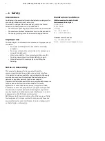
Digital Positioner for the
positioning of pneumatically
controlled final control elements.
CI/TZIDC/110/120-E
N
Rev. E
09.2018
—
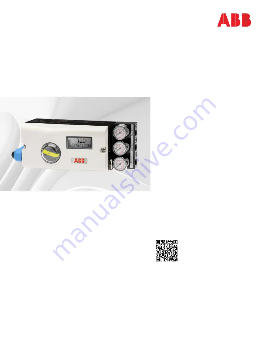
TZIDC
TZIDC-110
TZIDC-120
Introduction
The TZIDC, TZIDC-110, TZIDC-120 is an electronically
configurable positioner with communication
capabilities designed for mounting on pneumatic
linear or rotary actuators.
Fully automatic determination of the control
parameters and adaptation to the positioner allow
for considerable time savings as well as optimum
control behavior.
Additional Information
Additional documentation on TZIDC, TZIDC-110,
TZIDC-120 is available for download free of charge at
www.abb.com/positioners.
Alternatively simply scan this code:
—
We reserve the right to make technical changes or modify the contents of this document
without prior notice. With regard to purchase orders, the agreed particulars shall prevail.
ABB does not accept any responsibility whatsoever for potential errors or possible lack of
information in this document.
We reserve all rights in this document and in the subject matter and illustrations contained
therein. Any reproduction, disclosure to third parties or utilization of its contents – in whole or
in parts – is forbidden without prior written consent of ABB.
Copyright© 2018 ABB
All rights reserved
3KXE341007R4401


