background image

— 

A B B ME A SUR EMENT & A N A LY TIC S | COMMISSIONING INSTRUC TION
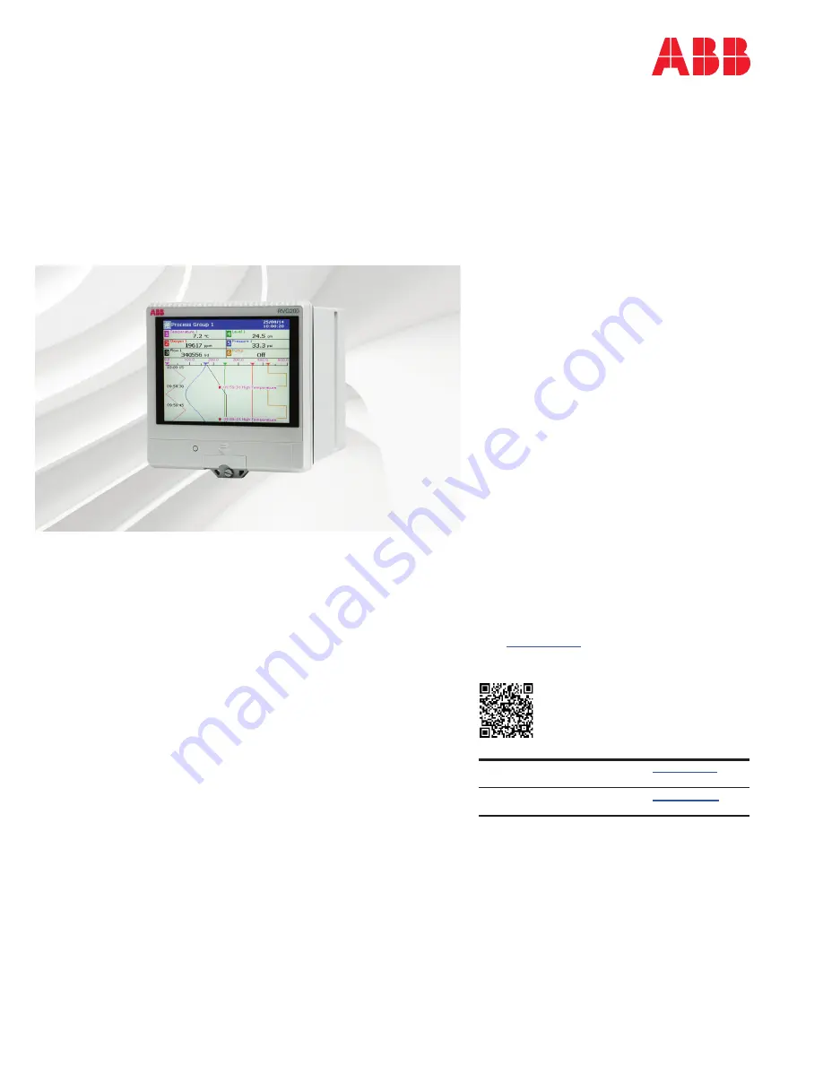
ScreenMaster RVG200

Paperless recorder

Measurement made easy

Introduction

This publication provides the following 
commissioning instructions for the ScreenMaster 
RVG200 paperless recorder:

Locating the recorder  
(location requirements)

Panel-mounting the recorder  
(installation requirements to achieve IP66 / 
NEMA 4X hose-down rating)

Electrical connections  
(AC and DC min. / max. values and fuse 
requirements)

Navigation 
(navigating the user-interface quickly and 
effectively)

Menus overview 
(menu familiarization)

Basic setup 
(steps required for first-time use)

Symbols and icons 
(a schedule of icons / warning symbols  
that may be displayed during operation)

For more information

Further publications for the ScreenMaster RVG200 
paperless recorder are available for free download 
from 

www.abb.com

 (see links and reference 

numbers below) or by scanning this code:

Search for or click on:

RVG200 paperless recorder 


Operating instructions

OI

/RVG200-EN

RVG200 paperless recorder 


Datasheet

DS

/RVG200-EN


Commissioning 
your RVG200

Summary of Contents for ScreenMaster RVG200

Page 1: ...s and fuse requirements 4 Navigation navigating the user interface quickly and effectively 5 Menus overview menu familiarization 6 Basic setup steps required for first time use 7 Symbols and icons a s...

Page 2: ...easurement Control and Laboratory Use and complies with US NEC 500 NIST and OSHA Safety conventions WARNING In this manual a warning is used to indicate a condition which if not met could cause seriou...

Page 3: ...ted to the installation of firewalls application of authentication measures encryption of data installation of anti virus programs etc to protect the product the network its system and the interface a...

Page 4: ...0 RVG200 RVG200 RVG200 Ambient temperature 50 C 122 F Max 0 C 32 F Min Eye level location Humidity 5 to 95 Avoid vibration Figure 1 Locating the recorder 2 Panel mounting the recorder Referring to Fig...

Page 5: ...rm to either IEC 60227 or IEC 60245 The terminals accept cables from 0 8 to 2 5 mm2 18 to 14 AWG The recorder conforms to Installation Category II of IEC 61010 All connections to secondary circuits mu...

Page 6: ...igure 4 1 Make connections to the power supply terminals module position E as follows AC supply terminals 1 line 2 neutral 3 ground or DC supply terminals 4 5 IMPORTANT NOTE Tighten terminal screws to...

Page 7: ...old junction assembly fitted Inputs 1 to 6 RTD R THC Volt free digital input mV V ma digital input V A B C D Analog Input A B C D Relay C D Hybrid E Power supply RJ45 USB 100 to 240 V AC 24 V DC Input...

Page 8: ...lay Operator menu icons page 2 of 2 Exit Operator menus return to previous view Display associated menus Access dialog Accept settings Exit display Figure 7 Navigating menus Navigating groups and view...

Page 9: ...or Log view Recorder functions are accessed by pressing the icon associated with the required function Select Group Operator Message Screen Capture Auto Group Scroll Trace Select Start Batch Select Vi...

Page 10: ...nal storage media c Create a new configuration based on the instrument s default configuration System Configuration Common Functions Groups Logic Editor Channels Maths equations I O Configuration menu...

Page 11: ...Points Menu enables Bar Bar graph view enable Bar graph markers Menu enables Batch if option enabled Enable Batch Recording Start Stop Abort Operator Login Batch Number Field 1 3 Title Channels Setup...

Page 12: ...P Implementation Slave Modbus TCP Port Reverse IEEE Data Implementation Master Modbus TCP Port Poll Rate Poll fail limit Response Timeout Client Authorization TCP TCP Client Access Authorized IP 1 6 C...

Page 13: ...rn to the Common Configuration level Time menu options Setup Groups and Channel allocation 1 Press the Setup tab and at the Number of Groups field press and enter the number of Groups required Press t...

Page 14: ...O page displaying fitted I O modules IMPORTANT NOTE I O modules are detected automatically 2 Press the icon associated with the required module to display the dialog and fields associated with that m...

Page 15: ...Active Alarm event icons Totalizer icons Audit log icons High process alarm Low process alarm Delayed high process alarm Delayed low process alarm High latch alarm Low latch alarm Fast rate alarm Slow...

Page 16: ...right to make technical changes or modify the contents of this document without prior notice With regard to purchase orders the agreed particulars shall prevail ABB does not accept any responsibility...

Reviews: