background image

SACO 16D3
Annunciator unit

User´s manual and Technical description

Summary of Contents for SACO 16D3

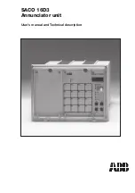
Page 1: ...SACO 16D3 Annunciator unit User s manual and Technical description ...

Page 2: ...operation for relays on SWOM 16A1 23 Selection of output contact mode for output relay on SWIM 2A1 24 Operation instructions 25 First out alarm indication 26 Event sequence register 27 Programming 28 Programming technique 28 Programming push buttons 30 Channel related parameters 30 Selection of channel input delay 30 Selection of channel resetting delay 30 Selection of field contact type or pulse ...

Page 3: ...in the external acknowledge reset circuits Thus no separate power units are needed for the field contact circuits The unit is provided with 20 output relays for signal transfer Two of these relays are used as group alarm outputs one is to be used for controlling an audible device and the other for the internal supervision system The other 16 output relays can be used either as input signal followi...

Page 4: ...mation When a change of state has been detected the alarm channel is activated and if the situation persists for a longer time than the specified channel input delay time the event will be registered The visual indicators and the auxiliary output relays respond to the situation according to the functional program they have been given The annunciator unit can be acknowledged and resetwithapush butt...

Page 5: ...panel can be reduced by 40 80 or 120 mm by using a raising frame The cast aluminum alloy mounting frame is stove finishedwithabeigesemiglosscarbamide resin paint and provided with a rubber gasket which provides a degree of protection by enclo suretoIP54betweenthemountingcaseandthe panel The mounting case is also provided with a glass clear UV stabilized polycarbonate lid with a sealable locking sc...

Page 6: ...pply module 0 V 48 V Field contact Galvanic isolation Fig 3 Principle of alarm channel input Alarm channel functions An alarm channel is composed of a number of functional blocks illustrated below The lists of variables underneath some of the blocks indi cate that a certain parameter can be selected from a set of given values i e the parameter can beprogrammed Theselectedparameterisshown in the nu...

Page 7: ...n duration the operation sequence memory is activated The channel input delay can be selected from a set of eight alternative values from the front panel 0 5 ms 1 20 ms 2 100 ms 3 1 s 4 5 s 5 20 s 6 60 s 7 160 s 8 another value which is programmed via the serial interface Via the serial interface the channel input delay can be freely programmed Refer to the param eter list in the end of this manua...

Page 8: ...te reset of audible alarm 2 ISA M 1 manual reset separate reset of audible alarm 3 ISA R 1 manual reset separate reset of audible alarm visual ringback on return 4 DIN 19235 manual reset after return to normal if acknowledged while alert visual ringback on return if acknowledged before return to normal The above operational sequences are common to all the 16 channels However the sequences can be a...

Page 9: ...ntact Visual alarm indicator Acknowledge Reset of audible output Silence Audible output Reset Field contact Visual alarm indicator Acknowledge Reset of audible output Silence Audible output Reset Automatic reset separate reset of audible output ISA A 1 Manual reset separate reset of audible output ISA M 1 Manual reset visual ringback and separate reset of audible output ISA R 1 Manual reset visual...

Page 10: ...urbances the alarm an nunciator unit has been provided with an event register which enables the incoming and disap pearing alarms to be read out The register holds 9 events which can be read out on the digital display step by step using the push button The latest youngest information i e address No 9 is read out first and then the events are represented in the display one by one until address No 1...

Page 11: ...nnunciator unit also includes a channel matrix register which operates in parallel with the event register and in which each channel corresponds to one bit If a channel is activated duringanoverflowsituationoftheevenregister the corresponding bit in the matrix register is activated Fig 9 Event registration in SPACOM systems Overflow Overflow Time Slave Channel Code 2 1 500 Adding of users text Eve...

Page 12: ... two relays on the relay card operate in parallel with the fixed group alarm relay outputs When the relays of the output relay module are used as pure input signal following output ele ments the output relays completely follows the input field signal Any possible programmed channel input or output delay is in this case neglected Fig 10 Principle diagram of reflashes 1 Grouping 16 Group alarm 16 Gr...

Page 13: ...joinsinanalreadyactivegroupalarmbunch 4 FCFR AACR Field Contact Following Reflash and Action Controlled Reflash se figure below Channel input delays Channel reset delay Alarm 1 Alarm 2 Acknowledge Signal following Alarm memory following Pulse type Signal following with break FCFR AACR Fig 11 Principlediagramforthedifferentreflashsignaltypes Thealarmsignals1and2aregrouped to the same group alarm re...

Page 14: ...ase refer to Standardized operational sequences on page 8 The audible device can be silenced by means of the acknowledge reset push button or by means ofanexternalcontrolsignalappliedtotheremote silence control input 17 of the annunciator unit An incoming alarm signal for which only the audible alarm has been silenced but the alarm signal has not been acknowledged nor reset will not produce a new ...

Page 15: ...ut relay 1 Reflash and communication interlocking Internal self supervision Fault 24 v undervoltage 5 V over and undervoltage 48 V undervoltage Hardware and software watchdog The following fault messages can be shown in the display 1 parameter memory circuit not available 2 faulty parameter memory checksum error 3 event register blocked due to field con tact pumping se below 4 undervoltage in fiel...

Page 16: ...ng levels are used it will effect the resolution on the time stamp for the event register The interlockings are distributed between the different channels via eight internal interlock ing lines see figure on page 17 Each channel can be connected to two inter lockinglines Thismeansthatalternativelyboth the interlocking inputs of an alarm channel are connected to two different interlocking lines or ...

Page 17: ...d when configuring the interlocking scheme INTERLOCKING GROUPS 1 2 3 4 5 6 7 8 Channel 1 __ Function 1 Function 2 Channel 2 __ Function 1 Function 2 Channel 3 __ Function 1 Function 2 Channel 4 __ Function 1 Function 2 Channel 5 __ Function 1 Function 2 Channel 6 __ Function 1 Function 2 Channel 7 __ Function 1 Function 2 Channel 8 __ Function 1 Function 2 Channel 9 __ Function 1 Function 2 Channe...

Page 18: ... 5 34 SPACOM 2 EN1 and the LON Talk proto col is described in the document LON bus LON Works network in protection and control systems 1MRS750035 MTD EN The speed of the serial communication is nor mally 9600 bits s Through the serial communication the follow ing information is read from the unit the event registers including the time mark ings the state of the channels and of the system the progr...

Page 19: ... annunciator unit is equipped with one power supply module but with two identical supply voltage inputs figure 17 Generally only one of the inputs is used but the annuncia tor can be supplied from two sources It must however be noticed that the two supply inputs are galvanically connected Thus in case two supplies are used it is recommended that the two supply sources are galvanically isolated If ...

Page 20: ...ame SPA ZX 303 120 mm raising frame The corresponding mounting brackets are de livered along with the raising frames The mounting frame is furnished with a rubber gasket which provides a degree of protection by enclosure to IP 54 between the case of the annunciator and the mounting panel Raising frame SPA ZX 301 SPA ZX 302 SPA ZX 303 209 169 129 74 114 154 a b 226 162 136 229 283 249 20 34 a b Pan...

Page 21: ... 96 95 94 93 92 91 90 89 88 87 86 85 84 83 82 81 80 79 78 77 76 75 74 73 REL 1 com REL 2 REL 3 com REL 4 REL 5 com 72 71 70 69 68 67 66 65 64 63 62 61 60 59 58 57 56 55 54 53 52 51 50 49 CH1 CH11 CH9 CH10 CH12 CH13 CH14 CH15 CH16 CH2 CH3 CH4 CH5 CH6 CH7 CH8 24 23 22 21 20 19 18 17 16 15 14 13 12 11 10 9 8 7 6 5 4 3 2 1 48V Rx Tx SIGNAL GND GROUP AL 1 RTS FOR SPA ZC N L N L RESET AUD RESET GROUP AL...

Page 22: ...ndows for the 16 channels The channel legend texts are applied on a drawing filmalsosquare ruledtoform16textfields The drawing film can be inserted in a slot along the left hand edge of the front plate see figure 22 The front plate including the legend text film and the screened plastic overlay are kept in place by means of four finger screws The legend text may be written with a drawing ink pen o...

Page 23: ...isible one with a connector marked SIGNAL FOL LOWER andtheotherwithaconnectormarked GROUPALARM Theoneneededissnapped to the counter connector on the output relay module SWOM 16A1 see the figure below Nowthealarmmodulecanbereinsertedandthe front plate can be refitted TheoutputcontactoftherelaymoduleSWOM 16A1 are normally open NO contacts If the GROUPALARM functionhasbeenselected the first two outpu...

Page 24: ...es may be present in the auxiliary reflash contact circuits WhentheInput Outputmodulehasbeenwith drawn from the case the PCBs can be separated from each other so that the retaining tongues of the plastic spacing plugs are depressed and the upper PCB is lifted The jumper wires on the PCBcorrespondstotheoutputrelaysasfollows W1 reflash output relay 1 W2 reflash output relay 2 W3 self supervision sys...

Page 25: ...terpush buttonsfortheannunciatorunitSACO16D3 During a normal process condition when no alarms are active and when all acknowledges resets have been performed the only indicator glowing on the front panel is the ON LED When alarm signals are received the alarm channelsstartsandthevisualLEDalarmindica tors are activated according to the selected se quence programs At the same time the first alarm ch...

Page 26: ...ndicated with a letter A and the channel number in the four digit display Channel 1 Channel 2 Channel 3 Channel 16 First out alarm memory Reset Digital display Not used Type of event A incoming alarm Channel number 1 16 Fig 27 Principle of the first out alarm indication The first out alarm indication is removed from the display with the acknowledge reset push button ...

Page 27: ...ds in the same direction IMPORTANT When the annunciator unit is turned into the programming mode by the push button the information in the event sequence register is automatically erased The information in the event sequence register is also lost iftheauxiliary supply of the annunciator unit is interrupted However the event register for the serial com munication will not been reset when the unit i...

Page 28: ...tor unit has been mounted at site during the commis sioning work By means of a plug selector located on the PCB just behind the front panel the switching over of the annunciator unit into the programming mode can be prohibited In this way the pro gram memory of the annunciator unit can be protected against unauthorized access Programming technique The annunciator unit is programmed by means of the...

Page 29: ...rammed The procedure when it goes back from programming mode is the same as when it starts up S 1 S 2 Fig 31 Selector plugs IMPORTANT The plug selector which is used to enable or prohibit programming of the annunciator unit can be located in two places named S1 and S2 Programming is prohibited when the selector plug is located in position S2 and enabled when the selector plug is in the position S1...

Page 30: ...ated parameters Selection of channel input delay The pointer LED marked INPUT is called up with the parameter selector push button and the channel to be programmed is chosen with the channel selector The cursor is moved to the leftmost digit of the display with the cursor control push button The concerned digit starts blinking The blinking number displayed correspondstothefollowingvaluesofthechann...

Page 31: ...ncethathasbeenselectedforthewhole annunciator unit se section Selection of alarm sequence type on page 34 1 normal sequence i e the same operation sequence as has been selected for the whole annunciator unit but extended with an au dible ringback feature upon return to nor mal of an alarm channel Applies only to the sequences 3 ISA R 1 and 4 DIN 19235 2 field contact following indication without a...

Page 32: ...h group 1 02 output reflash group 2 16 output reflash group 16 The reflash group in question is called up with the data value selector push button after which the cursor is moved to digits three and four from the left of the display with the cursor control push button The two digits are indicating the mode of reflash alarm signal for the selected output reflash group as follows 0 field contact fol...

Page 33: ... the enter command push button The selection relating to the second channel interlocking function is carried out in the same way as the selection of the first interlocking function butinthiscasethethirddigitfromthe left of the display indicates the type of interlock ingandthefourthdigitstatesthecorresponding interlocking line IMPORTANT If more than three interlocking levels are used i e a channel ...

Page 34: ...LE starts glowing The cursor is then moved to the fourth digit from the left of the display with the cursor control push button The fourth digit corresponds to one of the following functions 0 sync pulse receiver when not connected to a higher level system 1 sync pulsetransmitter whennotconnected to a higher level system 2 9600 bits s serial communication 3 4800 bits s 4 2400 bits s 5 1200 bits s ...

Page 35: ...ked not grouped 1 group 1 2 group 2 3 group 3 4 group 4 5 group 5 6 group 6 7 group 7 8 group 8 0 interlocking output 1 channel reflash A interlocked 2 channel interlocked 3 channel interlocked not grouped 1 group 1 2 group 2 3 group 3 4 group 4 5 group 5 6 group 6 7 group 7 8 group 8 Group alarm number Type of reflash relay function 01 group alarm relay 1 02 group alarm relay 2 16 group alarm rel...

Page 36: ... Channel indication Group Interlock Type of interlocking Interlocking group Channel reflash A Channel reflash B Type of interlocking Interlocking group Interlock funct 1 Interlock funct 2 Output Group alarm number Type of reflash relay function Module Unit identification number Sequence Serial communication Fig 33 Parameter chart ...

Page 37: ...el 8 __ Function 1 Function 2 Channel 9 __ Function 1 Function 2 Channel 10 __ Function 1 Function 2 Channel 11 __ Function 1 Function 2 Channel 12 __ Function 1 Function 2 Channel 13 __ Function 1 Function 2 Channel 14 __ Function 1 Function 2 Channel 15 __ Function 1 Function 2 Channel 16 __ Function 1 Function 2 TYPE OF INTERLOCKING 0 interlocking output 1 reflash A interlocking input 2 channel...

Page 38: ...ult when parameter A is read out 0 both alarm and status channels are printed out 1 only alarm channels are printed out 2 no out printing S19 0 Pumping supervision output relay 00 not connected 01 output relay 1 02 output relay 2 16 output relay 16 S33 48 0 Control of the output relay 1 16 over the SPA bus 0 not active 1 changing of state on off 2 pulse activation S49 64 0 Pulse length of output r...

Page 39: ...nd 4 active FFFF all 16 channels active V51 Status information of the overflow matrix register HEX coded form 0000 no active channels 0001 channel 1 active 0002 channel 2 active 0003 channel 1 and 2 active 0004 channel 3 active 0005 channel 1 and 3 active 0006 channel 2 and 3 active 0007 channel 1 2 and 3 active 0008 channel 4 active 0009 channel 1 and 4 active 000A channel 2 and 4 active 000B cha...

Page 40: ... 8 O1 16 Sate of output relay 1 16 0 not active state 1 active state C 0 Status information of module 0 when read normal state when written resets the status register 1 CPU reset has occurred 2 overflow of the event register has occurred 3 1 2 F SACO Type designation of module 16D2B T Time setting 0 000 59 999 time in seconds and milliseconds L Event sequence register Time channel and event code B...

Page 41: ...16 S6 0 Channel reflash B 0 not connected 1 16 connected to reflash group 1 16 S7 0 Interlocking signal 1 type specification 0 interlocking output 1 interlocking input reflash A blocked 2 interlocking input entire channel return as acknowledged alarm 3 interlocking input entire channel return as new alarm S8 0 Interlocking signal 1 grouping 0 not connected 1 8 connected to interlocking line 1 8 S9...

Page 42: ... selectable 5 ms 20 ms 100 ms 1 s 5 s 20 s 60 s or 160 s Other values possible over the serial communication Max counting frequency for pulse counter 3 Hz factory settings External acknowledge reset inputs Channel acknowledge reset Closing contact Reset of audible device Closing contact The control voltage for the acknowledge reset 48 V dc 20 circuits is taken from the internal supply Reflash sign...

Page 43: ...m and acknowledge reset inputs to the frame output relay contacts to the frame auxiliary supply circuits to the frame inputs outputs and supply circuits between themselves Dielectric test voltage as per IEC 255 5 2 kV 50 Hz 1 min and SS 436 15 03 Impulse test voltage as per IEC 255 5 5 kV 1 2 5 µs 0 5 J and SS 436 15 03 High frequency interference test voltage as per 2 5 kV 1 MHz IEC 255 6 and SS ...

Page 44: ... if the atmosphere around the annunciator unit holds chemically active gases or dust the modules ought to be visually inspected in association with the sec ondarytestingbeingperformedorwheneverthe plug in modules are withdrawn from the case At the visual inspection the following things should be noted possible mechanical damage of the mounting case mountingbracketsorframe plasticlidor its rubber g...

Page 45: ... ZC 21 MM S Fiber optical module plastic out glass in SPA ZC 21 BM S Fiber optical module glass out plastic in SPA ZC 21 MB S Fiber optical module plastic out plastic in SPA ZC 17 BB S Fiber optical module glass out glass in SPA ZC 17 MM S Fiber optical module plastic out glass in SPA ZC 17 BM S Fiber optical module glass out plastic in SPA ZC 17 MB S Raising frames Raising frame 40 mm SPA ZX 301 ...

Page 46: ...46 ...

Page 47: ...47 ...

Page 48: ...1MRS 751354 MUM EN ABB Oy Distribution Automation P O Box 699 FI 65101 Vaasa FINLAND Tel 358 0 10 22 11 Fax 358 0 10 22 41094 www abb com substationautomation ...

Reviews: