background image

 — 

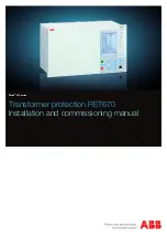
RELION®


670 SERIES

6

70

/650

 series 

IEC

Version 2.2 

Quick start guide

Summary of Contents for Relion 670 series

Page 1: ...RELION 670 SERIES 670 650 series IEC Version 2 2 Quick start guide...

Page 2: ......

Page 3: ...Document ID 1MRK 500 129 UEN Issued June 2018 Revision A Product version 2 2 Copyright 2018 ABB All rights reserved...

Page 4: ......

Page 5: ...ocal HMI display 11 Case from the front and rear sides 13 Section 5 Powering up the IED 19 How to know the voltage level 19 How to connect to the power supply 20 Energizing the IED 21 Section 6 LHMI o...

Page 6: ...Setting up communication between PCM600 and the IED 38 Section 9 Working with the PCM software 43 Table of contents 2 670 650 series 2 2 IEC Quick start guide...

Page 7: ...guide provides instructions to setup with a preconfigured IED however it is also useful for the customized version of the IED The guide describes basic instructions only For complete information see t...

Page 8: ...4...

Page 9: ...v2 Observe the warnings during all types of work related to the product GUID C9B6638A 57E7 4E05 9A33 A60E359C54AF v1 Only electrically skilled persons with the proper authorization and knowledge of an...

Page 10: ...site configuration This is class 1 equipment that shall be earthed M2367 2 v1 Never disconnect the secondary connection of current transformer circuit without short circuiting the transformer s second...

Page 11: ...tive wrist strap connected to protective earth when replacing modules Electrostatic discharge ESD may damage the module and IED circuitry M2698 2 v2 Take care to avoid electrical shock during installa...

Page 12: ...8...

Page 13: ...information to verify that the received product is correct 3 2 2 Checking delivery items GUID 2A6D8F5A 470F 40D1 9EAE 60DE4DD85EE6 v1 Check that all items are included in the delivery in accordance w...

Page 14: ...ABB immediately if there are any discrepancies in relation to the delivery documents Section 3 1MRK 500 129 UEN A Unpacking and inspecting 10 670 650 series 2 2 IEC Quick start guide...

Page 15: ...0 1 v1 4 1 1 Variants of case size with local HMI display M15024 3 v6 IEC04000458 2 en psd IEC04000458 V2 EN US Figure 2 1 2 19 case with local HMI display 1MRK 500 129 UEN A Section 4 IED hardware 67...

Page 16: ...762 V2 EN US Figure 3 3 4 19 case with local HMI display IEC04000460 2 en psd IEC04000460 V2 EN US Figure 4 1 1 19 case with local HMI display Section 4 1MRK 500 129 UEN A IED hardware 12 670 650 seri...

Page 17: ...K002801 AC 2 670 1 2 PG V4 EN US Rear position Module X11 PSM X31 and X32 etc to X51 and X52 BIM BOM SOM IOM or MIM X301 X302 X303 X304 SFP X305 LDCM X306 LDCM or OEM X3061 X3062 SFP if OEM is selecte...

Page 18: ...sition Module X11 PSM X31 and X32 etc to X101 and X102 BIM BOM SOM IOM or MIM X301 X302 X303 X304 SFP X305 LDCM X306 LDCM X3061 X3062 SFP if OEM is selected X311 A B C D SLM X312 LDCM IRIG B GTM X313...

Page 19: ...Rear position Module X11 PSM X31 and X32 etc to X71 and X72 BIM BOM SOM IOM or MIM X301 X302 X303 X304 SFP X305 LDCM X306 LDCM X3061 X3062 SFP if OEM is selected X311 A B C D SLM X312 LDCM IRIG B GTM...

Page 20: ...4 EN US Rear position Module X11 PSM X31 and X32 etc to X161 and X162 BIM BOM SOM IOM or MIM X301 X302 X303 X304 SFP X305 LDCM X306 LDCM X3061 X3062 SFP if OEM is selected X311 A B C D SLM X312 LDCM I...

Page 21: ...1 PSM X31 and X32 etc to X131 and X132 BIM BOM SOM IOM or MIM X301 X302 X303 X304 SFP X305 LDCM X306 LDCM X3061 X3062 SFP if OEM is selected X311 A B C D SLM X312 LDCM IRIG B GTM X313 X322 X323 LDCM I...

Page 22: ...18...

Page 23: ...ee the label on the right hand side of the IED to know the voltage level for the IED The label also contains data such as IED serial number and analog input ranges For example see Figure 5 10 9 8 7 7...

Page 24: ...X11 is a 5 input phoenix type contact See Figure 6 for example IEC08000471 BG V1 EN US Figure 6 Rear view of the 1 2 x 19 IED 1 Connect wires or cables to the IED terminals see Figure 7 for PSM conne...

Page 25: ...7 876C 4CC3CE706347 v4 Before connecting the auxiliary power check that the terminal strip is wired and placed correctly Remove the protective film from the top side of the unit During IED start up yo...

Page 26: ...22...

Page 27: ...0600428 v19 The LHMI keypad contains push buttons which are used to navigate in different views or menus The push buttons are also used to acknowledge alarms reset indications provide help and switch...

Page 28: ...with object control navigation and command push buttons and RJ 45 communication port 1 5 Function button 6 Close 7 Open 8 Escape 9 Left 10 Down 11 Up 12 Right 13 Key 14 Enter 15 Remote Local 16 Uplink...

Page 29: ...controlled is selected from the single line diagram Table 6 Object control push buttons Name Description Close Closing the object The LED indicates the current object state Open Opening the object The...

Page 30: ...electing pages in the SLD Changing the active digit of a parameter when entering a new setting value Key Activating the authorization procedure when the user is not logged in Logging out when the user...

Page 31: ...F360EA5 v13 The LHMI includes a graphical monochrome liquid crystal display LCD with a resolution of 320 x 240 pixels The character size can vary The amount of characters and rows fitting the view dep...

Page 32: ...shows the menu content The status area shows the current IED time the user that is currently logged in and the object identification string which is settable via the LHMI or with PCM600 If text pictu...

Page 33: ...Each function button has a LED indication that can be used as a feedback signal for the function button control action The LED is connected to the required signal with PCM600 IEC13000281 1 en vsd GUI...

Page 34: ...lor LEDs in one LED group can indicate 45 different signals Altogether 135 signals can be indicated since there are three LED groups The LEDs are lit according to priority with red being the highest a...

Page 35: ...6 1 en vsd IEC16000076 V1 EN US Figure 13 OPENCLOSE_LED connected to SXCBR 6 1 4 Local HMI functionality 6 1 4 1 Protection and alarm indication GUID 09CCB9F1 9B27 4C12 B253 FBE95EA537F5 v17 Protectio...

Page 36: ...n the reset menu on the LHMI press Flasing Configuration mode Alarm indicators The 15 programmable three color LEDs are used for alarm indication An individual alarm status signal connected to any of...

Page 37: ...fferent tasks and functions and control the whole substation PCM600 can operate with many different topologies depending on the customer needs For more information see PCM600 documentation 7 1 1 Conne...

Page 38: ...d IED Most modern PCs can automatically crossover the straight connection RJ45 cables For example if a Gigabit Ethernet is used in the system a crossover cable is not required If it is unsure whether...

Page 39: ...J45 cable connection to the front port of the IED The default IP address of the front port of the IED 10 1 150 3 is used to establish a connection 1MRK 500 129 UEN A Section 7 Connecting to the PCM600...

Page 40: ...36...

Page 41: ...re shows this concept and the addresses are used as an example other addresses can also be used Subnet Mask for both 255 255 255 0 IEC18000032 1 en vsdx 670 IED IP address Front Port 10 1 150 3 PC IP...

Page 42: ...LAN WAN network 4 Configure the IED IP addresses in the PCM600 project for each IED to match the IP addresses of the physical IEDs Setting up IP addresses Communication between the IED and PCM600 is e...

Page 43: ...in between If an IED is equipped with optical LC interface a converter between RJ 45 and LC is needed 1 Select Search programs and files in the Start menu in Windows IEC13000057 1 en vsd IEC13000057...

Page 44: ...C13000059 1 en vsd IEC13000059 V1 EN US Figure 18 Right click Local Area Connection and select Properties 4 Select the TCP IPv4 protocol from the list of configured components using this connection an...

Page 45: ...ddress and define IP address and Subnet mask if the front port is used and if the IP address is not set to be obtained automatically by the IED see Figure 20 The IP address must be different from the...

Page 46: ...must belong to the same subnetwork for this set up to work Setting up the PC to access the IED via a network The same method is used as for connecting to the front port The PC and IED must belong to t...

Page 47: ...ration and settings from and to the IED After connecting the PCM software and modified network settings the system is ready to connect to the IED To operate with PCM600 there must be at least one IED...

Page 48: ...44...

Page 49: ...45...

Page 50: ...AB Grid Automation Products 721 59 V ster s Sweden Phone 46 0 21 32 50 00 abb com protection control Copyright 2017 ABB All rights reserved Specifications subject to change without notice 1MRK 500 129...

Reviews: