background image

 — 

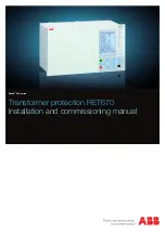
RELION®


670 SERIES

Transformer protection RET670 

Version 2.

1


Product guide

Summary of Contents for Relion 670 series

Page 1: ...RELION 670 SERIES Transformer protection RET670 Version 2 1 Product guide...

Page 2: ...rams 48 21 Technical data 49 22 Ordering for customized IED 124 23 Ordering for pre configured IED 135 24 Ordering for Accessories 141 Disclaimer The information in this document is subject to change...

Page 3: ...rther alternative backup protection Thermal overload overexcitation over under voltage and over under frequency protection functions are also available Breaker failure protection for each transformer...

Page 4: ...d but a maximum configuration with all optional functions are available as template in the graphical configuration tool An alternative for Autotransformers is also available as a configuration templat...

Page 5: ...A1 Other Functions available from the function library Optional Functions CC PDSC 52PD PD BRC PTOC 46 Iub VDC PTOV 60 Ud EC PSCH 85 Q CBAY 3 Control CCS SPVC 87 INd I ECRW PSCH 85 S SIMG 63 87 Id HZ P...

Page 6: ...BRC PTOC 46 Iub VDC PTOV 60 Ud EC PSCH 85 Q CBAY 3 Control CCS SPVC 87 INd I ECRW PSCH 85 S SIMG 63 87 Id HZ PDIF ZMH PDIS 21 Z NS4 PTOC 46I2 4 I2 TR1 ATCC 90 CV GAPC 2 I U SA PFRC 81 df dt SA PTOF 81...

Page 7: ...SA PTUF 81 f OEX PVPH 24 U f SMP PTRC 94 1 0 TCM YLTC 84 DRP RDRE DFR SER DR V MMXU MET U OV2 PTOV 59 2 3U REF PDIF 87N IdN I REF PDIF 87N IdN I EF4 PTOC 51N_67N 4 IN C MMXU MET I ZMQ PDIS 21 Z ZM RPS...

Page 8: ...I T3W PDIF 87T 3Id I Other Functions available from the function library Optional Functions BRC PTOC 46 Iub VDC PTOV 60 Ud EC PSCH 85 Q CBAY 3 Control CCS SPVC 87 INd I ECRW PSCH 85 S SIMG 63 87 Id HZ...

Page 9: ...VN MMXU MET UN WA1 WA2 W1_CT W3_CT W2_CT W2_VT W2_WA1_VT WA1 WA1 EF4 PTOC 51N 4 IN Other Functions available from the function library Optional Functions V MSQI MET UN ETP MMTR MET W Varh S SIMG 63 V...

Page 10: ...V2 PTUV 27 2 3U OV2 PTOV 59 2 3U ROV2 PTOV 59N 2 U0 S SIMG 63 S CILO 3 Control S CSWI 3 Control S XSWI 3 Control S XCBR 3 Control BRC PTOC 46 Iub TR1 ATCC 90 TR8 ATCC 90 TR8 ATCC 90 C MSQI MET Isqi CV...

Page 11: ...D98 851D 4AAC B386 B38B57718BD2 v12 1 1 Table 1 Example of quantities 2 number of basic instances 0 3 option quantities 3 A03 optional function included in packages A03 refer to ordering details 1MRK...

Page 12: ...or series compensated lines 0 5 ZDSRDIR 21D Directional impedance quadrilateral including series compensation 0 2 FDPSPDIS 21 Phase selection quadrilateral characteristic with fixed angle 0 2 2 B12 2...

Page 13: ...series compensated lines quadrilateral and mho 6 zones 0 1 ZMRPSB 68 Power swing detection 0 1 1 B12 1 B13 1 B12 1 B13 1 B12 1 B13 1 B12 1 B13 PSLPSCH Power swing logic 0 1 PSPPPAM 78 Pole slip out of...

Page 14: ...26 Thermal overload protection one time constant Celsius 0 2 LFPTTR 26 Thermal overload protection one time constant Fahrenheit 0 2 TRPTTR 49 Thermal overload protection two time constant 0 6 1 1B 1...

Page 15: ...2 2 2 2 LOVPTUV 27 Loss of voltage check 1 1 1 1 1 1 1 Frequency protection SAPTUF 81 Underfrequency protection 0 6 6 E01 6 E01 6 E01 6 E01 6 E01 SAPTOF 81 Overfrequency protection 0 6 6 E01 6 E01 6 E...

Page 16: ...tic voltage control for tap changer parallel control 0 4 1 H15 1 H15 1 H15 2 H18 1 H15 2 H18 2 2 H18 TCMYLTC 84 Tap changer control and supervision 6 binary inputs 0 4 4 4 4 4 4 TCLYLTC 84 Tap changer...

Page 17: ...p alarm 5 5 5 5 5 5 5 WRNCALH Logic for group warning 5 5 5 5 5 5 5 INDCALH Logic for group indication 5 5 5 5 5 5 5 AND GATE INV LLD OR PULSETIMER RSMEMORY SRMEMORY TIMERSET XOR Basic configurable lo...

Page 18: ...report 1 1 1 1 1 1 1 SPGAPC Generic communication function for Single Point indication 64 64 64 64 64 64 64 SP16GAPC Generic communication function for Single Point indication 16 inputs 16 16 16 16 1...

Page 19: ...UFCNT Event counter with limit supervision 30 30 30 30 30 30 30 TEILGAPC Running hour meter 6 6 6 6 6 6 6 Metering PCFCNT Pulse counter logic 16 16 16 16 16 16 16 ETPMMTR Function for energy calculati...

Page 20: ...VERTERQT 120 ORQT 120 PULSETIMERQT 40 RSMEMORYQT 40 SRMEMORYQT 40 TIMERSETQT 40 XORQT 40 Table 4 Total number of instances for extended logic package Extended configurable logic block Total number of...

Page 21: ...communication protocol 1 1 1 1 1 1 1 CHSEROPT DNP3 0 for TCP IP and EIA 485 communication protocol 1 1 1 1 1 1 1 MST1TCP MST2TCP MST3TCP MST4TCP DNP3 0 for serial communication protocol 1 1 1 1 1 1 1...

Page 22: ...D Physical device information 1 1 1 1 1 1 1 PCMACCS IED Configuration Protocol 1 1 1 1 1 1 1 SECALARM Component for mapping security events on protocols such as DNP3 and IEC103 1 1 1 1 1 1 1 FSTACCS F...

Page 23: ...RET670 A25 Scheme communication ECPSCH 85 Scheme communication logic for residual overcurrent protection 0 1 1 1 1 1 ECRWPSCH 85 Current reversal and weak end infeed logic for residual overcurrent pr...

Page 24: ...BO Signal matrix for binary outputs SMMI Signal matrix for mA inputs SMAI1 SMAI12 Signal matrix for analog inputs 3PHSUM Summation block 3 phase ATHSTAT Authority status ATHCHCK Authority check AUTHMA...

Page 25: ...ndication module 3 Differential protection Transformer differential protection T2WPDIF T3WPDIF M16104 3 v16 The Transformer differential protection is provided with internal CT ratio matching vector g...

Page 26: ...hase HZPDIF M13071 3 v13 High impedance differential protection single phase HZPDIF functions can be used when the involved CT cores have the same turns ratio and similar magnetizing characteristics I...

Page 27: ...peration speed of main protection Startup element would detect the evolving faults high impedance faults and three phase fault on weak side It is possible to block the each sub function of startup ele...

Page 28: ...oper fault loop in the distance function dependent on the fault type The heavy load transfer that is common in many transmission networks may make fault resistance coverage difficult to achieve Theref...

Page 29: ...the distance protection zone reach and cause unwanted operation Therefore the function has a built in algorithm for load encroachment which gives the possibility to enlarge the resistive setting of t...

Page 30: ...ith single phase autoreclosing High speed distance protection ZMFCPDIS is fundamentally the same function as ZMFPDIS but provides more flexibility in zone settings to suit more complex applications su...

Page 31: ...during pole slipping occurrences in the power system The OOSPPAM function detects pole slip conditions and trips the generator as fast as possible after the first pole slip if the center of oscillati...

Page 32: ...isolated networks or in networks with high impedance earthing the earth fault current is significantly smaller than the short circuit currents In addition to this the magnitude of the fault current i...

Page 33: ...mber of applications where such functionality is needed Some of them are detection of reversed active power flow detection of high reactive power flow Each function has two steps with definite time de...

Page 34: ...s each of them with inverse or definite time delayed OV2PTOV has a high reset ratio to allow settings close to system service voltage Two step residual overvoltage protection ROV2PTOV M13808 3 v10 Res...

Page 35: ...idelines 8 Multipurpose protection General current and voltage protection CVGAPCM13083 3 v6 The protection module is recommended as a general backup protection with many possible application areas due...

Page 36: ...es of main and pilot fused circuits VDSPVC blocking output can be configured to block functions that need to be blocked in case of faults in the voltage circuit Multipurpose filter SMAIHPAC GUID EB0B1...

Page 37: ...ce or up to three one phase devices Circuit breaker SXCBR M13489 3 v6 The purpose of Circuit breaker SXCBR is to provide the actual status of positions and to perform the control operations that is pa...

Page 38: ...station wide logics Single point generic control 8 signals SPC8GAPC SEMOD176462 4 v8 The Single point generic control 8 signals SPC8GAPC function block is a collection of 8 single point commands desig...

Page 39: ...able pulse or steady output Group alarm logic function ALMCALH GUID 16E60E27 F7A8 416D 8648 8174AAC49BB5 v3 The group alarm logic function ALMCALH is used to route several alarm signals to a common in...

Page 40: ...it transgression conditions and overflow Possibility to define a warning or alarm with the resolution of 10 milliseconds Retaining of the integration value Possibilities for blocking and reset Reporti...

Page 41: ...in the recording Every disturbance report recording is saved in the IED in the standard Comtrade format as a reader file HDR a configuration file CFG and a data file DAT The same applies to all events...

Page 42: ...d one single logical signal to other systems or equipment in the substation Generic communication function for Measured Value MVGAPC SEMOD55872 5 v9 Generic communication function for Measured Value M...

Page 43: ...MTR GUID 6898E29B DA70 421C 837C 1BBED8C63A7A v2 Measurements function block CVMMXN can be used to measure active as well as reactive power values Function for energy calculation and demand handling E...

Page 44: ...50 9 2LE allows Non Conventional Instrument Transformers NCIT with Merging Units MU or stand alone Meging Units to exchange information with the IED and simplifies SA engineering LON communication pro...

Page 45: ...8 3 v4 The binary output module has 24 independent output relays and is used for trip output or any signaling purpose Static binary output module SOM SEMOD174196 4 v4 The static binary output module h...

Page 46: ...B time synchronizing module is used for accurate time synchronizing of the IED from a station clock The Pulse Per Second PPS input shall be used for synchronizing when IEC 61850 9 2LE is used Electric...

Page 47: ...265 9 10 47 448 3 17 65 242 1 9 53 255 8 10 07 430 3 16 86 190 5 7 50 428 3 16 86 465 1 18 31 228 6 9 00 482 6 19 00 The H and K dimensions are defined by the 19 rack mounting kit Mounting alternative...

Page 48: ...01 AF Connection diagrams for Configured products Connection diagram RET670 2 1 A10 1MRK002803 PF Connection diagram RET670 2 1 A30 1MRK002803 PA Connection diagram RET670 2 1 B30 1MRK002803 PB Connec...

Page 49: ...ssociated main instrument transformers Note that for functions which measure an analogue signal which do not have corresponding primary quantity the 1 1 ratio shall be set for the used analogue inputs...

Page 50: ...10 Ir for 1 min 4 Ir continuously Dynamic withstand 250 Ir one half wave Burden 20 mVA at Ir 1 A 150 mVA at Ir 5 A max 350 A for 1 s when COMBITEST test switch is included Voltage inputs Rated voltag...

Page 51: ...rden 20 mVA at 110 V 80 mVA at 220 V all values for individual voltage inputs Note All current and voltage data are specified as RMS values at rated frequency M6389 1 v4 Table 9 MIM mA input module Qu...

Page 52: ...ue Nominal range Binary inputs 16 DC voltage RL 24 30 V 48 60 V 110 125 V 220 250 V RL 20 RL 20 RL 20 RL 20 Power consumption 24 30 V 50 mA 48 60 V 50 mA 110 125 V 50 mA 220 250 V 50 mA 220 250 V 110...

Page 53: ...10 125 V 220 250 V RL 20 RL 20 RL 20 RL 20 Power consumption 24 30 V 48 60 V 110 125 V 220 250 V max 0 05 W input max 0 1 W input max 0 2 W input max 0 4 W input Counter input frequency 10 pulses s ma...

Page 54: ...tage RL 24 30 V 48 60 V 110 125 V 220 250 V RL 20 RL 20 RL 20 RL 20 Power consumption 24 30 V 50 mA 48 60 V 50 mA 110 125 V 50 mA 220 250 V 50 mA 220 250 V 110 mA max 0 05 W input max 0 1 W input max...

Page 55: ...V DC Current carrying capacity Per relay continuous Per relay 1 s Per process connector pin continuous 8 A 10 A 12 A 8 A 10 A 12 A Making capacity at inductive load with L R 10 ms 0 2 s 1 0 s 30 A 10...

Page 56: ...ity Trip and Signal relays Fast signal relays parallel reed relay Binary outputs IOM 10 IOM 2 Max system voltage 250 V AC DC 250 V DC Min load voltage 24VDC Test voltage across open contact 1 min 250...

Page 57: ...operating time for the binary inputs and outputs SEMOD175395 2 v9 Table 17 SOM Static Output Module reference standard IEC 61810 2 Static binary outputs Function of quantity Static binary output trip...

Page 58: ...across open contact 1 min 1000 V rms Current carrying capacity Continuous 8 A 1 0 s 10 A Max operations with load 1000 Max operations with no load 10000 Making capacity at capacitive load with the ma...

Page 59: ...tions with no load 10000 Making capacity at inductive load with L R 10 ms 0 2 s 1 0 s 30 A 10 A Breaking capacity for AC cos j 0 4 250 V 8 0 A Breaking capacity for DC with L R 40 ms 48 V 1 A 110 V 0...

Page 60: ...ominal range Influence Frequency dependence operate value fr 2 5 Hz for 50 Hz fr 3 0 Hz for 60 Hz 1 0 Hz Frequency dependence for distance protection operate value fr 2 5 Hz for 50 Hz fr 3 0 Hz for 60...

Page 61: ...requency immunity test 150 300 V 50 Hz IEC 60255 26 Zone A Conducted common mode immunity test 15 Hz 150 kHz IEC 61000 4 16 Class IV Power frequency magnetic field test 1000 A m 3 s 100 A m cont IEC 6...

Page 62: ...nd humidity 93 IEC 60068 2 78 Damp heat test cyclic Test Db for 6 cycles at 25 to 55 C and humidity 93 to 95 1 cycle 24 hours IEC 60068 2 30 Table 26 CE compliance Test According to Immunity EN 60255...

Page 63: ...x IdMin restrained function Min 25 ms Max 35 ms Reset time at 10 x IdMin to 0 restrained function Min 5 ms Max 15 ms Operate time at 0 to 10 x Idunre unrestrained function Min 5 ms Max 15 ms Reset ti...

Page 64: ...ocking 40 0 of fundamental 1 0 of Ir M13081 1 v12 Table 30 High impedance differential protection single phase HZPDIF Function Range or value Accuracy Operate voltage 10 900 V I U R 1 0 of Ir at I Ir...

Page 65: ...tage phase to phase 1 100 of UBase 0 5 of Ur Independent time delay zero sequence current at 0 to 2 x Iset 0 000 60 000 s 0 2 or 40 ms whichever is greater Independent time delay low current operation...

Page 66: ...ange 0 5 30 x Ir Angle at 0 degrees and 85 degrees Positive sequence resistance 0 01 1000 00 phase Zero sequence reactance 0 10 9000 00 phase Zero sequence resistance 0 01 3000 00 phase Fault resistan...

Page 67: ...ms whichever is greater Operate time 25 ms typically IEC 60255 121 Reset ratio 105 typically Reset time at 0 1 x Zreach to 2 x Zreach Min 20 ms Max 50 ms M16024 1 v11 Table 34 Phase selection quadrila...

Page 68: ...o 105 typically Reset time at 0 5 to 1 5 x Zreach Min 30 ms Max 45 ms SEMOD173249 2 v7 Table 36 Full scheme distance protection quadrilateral for earth faults ZMMPDIS Function Range or value Accuracy...

Page 69: ...hase and phase to earth 10 1000 of IBase Positive sequence reactance 0 10 3000 00 phase 2 0 static accuracy 2 0 degrees static angular accuracy Conditions Voltage range 0 1 1 1 x Ur Current range 0 5...

Page 70: ...0 1 1 1 x Ur Current range 0 5 30 x Ir Angle at 0 degrees and 85 degrees Resistive reach positive sequence 0 10 1000 00 phase Reactive reach zero sequence 0 50 9000 00 phase Resistive reach zero seque...

Page 71: ...00 3000 00 ohm p Fault resistance reach Ph E and Ph Ph 0 01 9000 00 ohm l Dynamic overreach 5 at 85 degrees measured with CVTs and 0 5 SIR 30 IEC 60255 121 Reset ratio 105 typically Directional blind...

Page 72: ...ance reach Ph E and Ph Ph 1 00 9000 00 l Dynamic overreach 5 at 85 deg measured with CVT s and 0 5 SIR 30 Definite time delay to trip Ph E and Ph Ph operation 0 000 60 000 s 0 2 or 35 ms whichever is...

Page 73: ...0 000 60 0000 s 0 2 or 15 ms whichever is greater Timer for blocking the overreaching zones trip 0 000 60 0000 s 0 2 or 15 ms whichever is greater GUID 88E02516 1BFE 4075 BEEB 027484814697 v2 Table 44...

Page 74: ...l voltage at 1 2 x Uset to 0 8 x Uset 0 000 60 000 s 0 2 or 25 ms whichever is greater Operating mode No Filter NoPref Cyclic 1231c 1321c Acyclic 123a 132a 213a 231a 312a 321a GUID E8104D00 3183 4F55...

Page 75: ...500 of IBase Operate time at 0 to 2 x Iset Min 15 ms Max 25 ms Reset time at 2 to 0 x Iset Min 15 ms Max 25 ms Critical impulse time 10 ms typically at 0 to 2 x Iset Operate time at 0 to 10 x Iset Min...

Page 76: ...greater Minimum operate time for inverse curves step 1 4 0 000 60 000 s 0 2 or 35 ms whichever is greater Inverse time characteristics see table 157 table 158 and table 159 16 curve types See table 1...

Page 77: ...se Operate time at 0 to 2 x Iset Min 15 ms Max 25 ms Reset time at 2 to 0 x Iset Min 15 ms Max 25 ms Critical impulse time 10 ms typically at 0 to 2 x Iset Operate time at 0 to 10 x Iset Min 5 ms Max...

Page 78: ...e Table 157 Table 158 and Table 159 Second harmonic blocking 5 100 of fundamental 2 0 of Ir Minimum polarizing voltage 1 100 of UBase 0 5 of Ur Minimum polarizing current 2 100 of IBase 1 0 of Ir Real...

Page 79: ...egrees 2 0 degrees Operate current for directional release 1 100 of IBase For RCA 60 degrees 2 5 of Ir at I Ir 2 5 of I at I Ir Minimum polarizing voltage 1 100 of UBase 0 5 of Ur Minimum polarizing c...

Page 80: ...0 5 of Ur at U Ur 0 5 of U at U Ur Operate time for non directional residual overcurrent at 0 to 2 x Iset Min 40 ms Max 65 ms Reset time for non directional residual overcurrent at 2 to 0 x Iset Min...

Page 81: ...0 400 F 2 0 C 4 0 F Operate temperature 0 300 C 0 600 F 2 0 C 4 0 F Reset level temperature 0 300 C 0 600 F 2 0 C 4 0 F M13266 2 v9 Table 55 Thermal overload protection two time constants TRPTTR Func...

Page 82: ...s 0 2 or 20 ms whichever is greater Additional time delay for a second back up trip at 0 to 2 x Iset 0 000 60 000 s 0 2 or 20 ms whichever is greater Time delay for alarm for faulty circuit breaker 0...

Page 83: ...Step 2 at 0 5 to 2 x Sr and k 0 000 0 01 6000 00 s 0 2 or 40 ms whichever is greater SEMOD175200 2 v7 Table 60 Broken conductor check BRCPTOC Function Range or value Accuracy Minimum phase current fo...

Page 84: ...Sr Operate value voltage protection function for harmonic overload Definite time 10 500 0 5 of Ur at U Ur 0 5 of U at U Ur Operate value voltage protection function for harmonic overload Inverse time...

Page 85: ...se Inverse time characteristic step 1 2 2 2 I t K K 1 0 99 0 2 0 or 40 ms whichever is greater Reset time inverse characteristic step 1 2 2 2 I t K Reset Multiplier 0 01 20 00 5 0 or 40 ms whichever i...

Page 86: ...t 0 00 6000 00 s 0 2 or 40ms whichever is greater Definite time delay step 2 at 1 2 to 0 x Uset 0 000 60 000 s 0 2 or 40ms whichever is greater Minimum operate time inverse characteristics 0 000 60 00...

Page 87: ...45 ms whichever is greater Definite time delay high step step 2 at 0 to 1 2 x Uset 0 000 60 000 s 0 2 or 45 ms whichever is greater Minimum operate time Inverse characteristics 0 000 60 000 s 0 2 or 4...

Page 88: ...ms Operate time start at 0 to 1 2 x Uset Min 20 ms Max 35 ms Reset time start at 1 2 to 0 x Uset Min 5 ms Max 25 ms Critical impulse time 10 ms typically at 0 to 2 x Uset Impulse margin time 15 ms typ...

Page 89: ...differential reset at 1 2 to 0 8 x UDTrip 0 000 60 000 s 0 2 or 40 ms whichever is greater SEMOD175210 2 v6 Table 68 Loss of voltage check LOVPTUV Function Range or value Accuracy Operate voltage 1 10...

Page 90: ...50 of Ubase UMin 50 150 of Ubase Exponent 0 0 5 0 tMax 0 010 60 000 s tMin 0 010 60 000 s 1 0 or 120 ms whichever is greater Exponent U UMin t tMax tMin tMin UNom UMin EQUATION1182 V1 EN US Equation 4...

Page 91: ...lue restore enable frequency 45 00 65 00 Hz 2 0 mHz Definite restore time delay 0 000 60 000 s 0 2 or 100 ms whichever is greater Definite time delay for frequency gradient trip 0 000 60 000 s 0 2 or...

Page 92: ...undercurrent at 2 to 0 x Iset step 1 2 0 00 6000 00 s 0 2 or 35 ms whichever is greater Overcurrent non directional Start time at 0 to 2 x Iset Min 15 ms Max 30 ms Reset time at 2 to 0 x Iset Min 15...

Page 93: ...rve types See table 161 High and low voltage limit voltage dependent operation step 1 2 1 0 200 0 of UBase 1 0 of Ur at U Ur 1 0 of U at U Ur Directional function Settable NonDir forward and reverse R...

Page 94: ...urve types See tables 157 and 158 Minimum operate time for inverse time characteristics 0 00 60 00 s 0 2 or 35 ms whichever is greater High voltage limit voltage dependent operation 30 0 100 0 of UBas...

Page 95: ...r Operate current zero sequence 1 100 of IBase 0 5 of Ir Operate voltage negative sequence 1 100 of UBase 0 5 of Ur Operate current negative sequence 1 100 of IBase 0 5 of Ir Operate voltage change le...

Page 96: ...main fuse failure at 1 to 0 x Ur Min 5 ms Max 15 ms Reset time block of main fuse failure at 0 to 1 x Ur Min 15 ms Max 30 ms Operate value alarm for pilot fuse failure 10 0 80 0 of UBase 0 5 of Ur Res...

Page 97: ...050 0 500 Hz 2 5 mHz Breaker closing pulse duration 0 050 60 000 s 0 2 or 15 ms whichever is greater tMaxSynch which resets synchronizing function if no close has been made before set time 0 000 6000...

Page 98: ...Load voltage auto correction 20 0 20 0 of UBase Duration time for the reverse action block signal 30 6000 s 0 2 or 600 ms whichever is greater Current limit for reverse action block 0 100 of I1Base Ov...

Page 99: ...on change before the value is accepted 1 60 s 0 2 or 200 ms whichever is greater Tap changer constant time out 1 120 s 0 2 or 200 ms whichever is greater Raise lower command output pulse duration 0 5...

Page 100: ...sal and weak end infeed logic for residual overcurrent protection ECRWPSCH Function Range or value Accuracy Operate mode of WEI logic Off Echo Echo Trip Operate voltage 3U0 for WEI trip 5 70 of UBase...

Page 101: ...PC instances Function Quantity with cycle time 3 ms 8 ms 100 ms TMAGAPC 6 6 GUID A05AF26F DC98 4E62 B96B E75D19F20767 v1 Table 84 Number of ALMCALH instances Function Quantity with cycle time 3 ms 8 m...

Page 102: ...E05E5FB1 23E7 4816 84F2 1FBFFDFF2B43 v1 Table 92 Number of PULSETIMER instances Logic block Quantity with cycle time Range or Value Accuracy 3 ms 8 ms 100 ms PULSETIMER 10 10 20 0 000 90000 000 s 0 5...

Page 103: ...e 3 ms 8 ms 100 ms INDEXTSPQT 10 10 GUID 77FEBE9B 0882 4E85 8B1A 7671807BFC02 v1 Table 100 Number of INVALIDQT instances Logic block Quantity with cycle time 3 ms 8 ms 100 ms INVALIDQT 6 6 GUID F25B94...

Page 104: ...10 30 0 000 90000 000 s 0 5 10 ms GUID 1C381E02 6B9E 44DC 828F 8B3EA7EDAA54 v1 Table 107 Number of XORQT instances Logic block Quantity with cycle time 3 ms 8 ms 100 ms XORQT 10 30 GUID 19810098 1820...

Page 105: ...verflow supervision TEIGAPC Function Cycle time ms Range or value Accuracy Elapsed time integration 3 0 999999 9 s 0 2 or 20 ms whichever is greater 8 0 999999 9 s 0 2 or 100 ms whichever is greater 1...

Page 106: ...4 0 x Ir 0 5 of Sr at S 0 5 x Sr 0 5 of S at S 0 5 x Sr 100 to 220 V 0 5 2 0 x Ir 0 2 of S Power factor cos 10 to 300 V 0 1 4 0 x Ir 0 02 100 to 220 V 0 5 2 0 x Ir 0 01 GUID 5E04B3F9 E1B7 4974 9C0B D...

Page 107: ...0 1 Ir I 0 5 Ir 0 5 degrees at 0 5 Ir I 4 0 Ir GUID 47094054 A828 459B BE6A D7FA1B317DA7 v6 Table 121 Voltage sequence measurement VMSQI Function Range or value Accuracy Voltage positive sequence U1...

Page 108: ...z Sampling rate 1 kHz at 50 Hz 1 2 kHz at 60 Hz Recording bandwidth 5 300 Hz GUID F034B396 6600 49EF B0A5 8ED96766A6A0 v6 Table 124 Insulation gas monitoring function SSIMG Function Range or value Acc...

Page 109: ...460E B02F C7D4F1937432 v9 Table 126 Circuit breaker condition monitoring SSCBR Function Range or value Accuracy Alarm level for open and close travel time 0 200 ms 3 ms Alarm level for number of opera...

Page 110: ...Table 131 Disturbance recorder Function Value Buffer capacity Maximum number of analog inputs 40 Maximum number of binary inputs 128 Maximum number of disturbance reports 100 Maximum total recording...

Page 111: ...y Input Module BIM Cycle time for report of counter value 1 3600 s SEMOD153707 2 v4 Table 134 Energy metering ETPMMTR Function Range or value Accuracy Energy metering kWh Export Import kvarh Export Im...

Page 112: ...Table 136 IEC 61850 9 2 communication protocol Function Value Protocol IEC 61850 9 2 Communication speed for the IEDs 100BASE FX M11927 1 v2 Table 137 LON communication protocol Function Value Protoc...

Page 113: ...m Plastic fiber 1 mm depending on optical budget calculation GUID 83EC40D0 ABCF 4292 B3DF 155C3A556B76 v3 Table 142 Galvanic X 21 line data communication module X 21 LDCM Quantity Range or value Conne...

Page 114: ...26 8 dB typical distance 80 km 50 mile 28 7 dB typical distance 120 km 68 mile Multi mode fiber glass 50 125 mm 11 5 dB typical distance about 2 km 1 mile Optical connector Type ST Type FC PC Type FC...

Page 115: ...according to IEC 60255 27 Equipment class I protective earthed Overvoltage category III Pollution degree 2 normally only non conductive pollution occurs except that occasionally a temporary conductivi...

Page 116: ...en ring lug terminal is ordered for Binary I O connections one blank slot is necessary between two adjacent IO cards Please refer to the ordering particulars for details 1MRK 504 155 BEN F Transformer...

Page 117: ...cally SEMOD55660 2 v3 Table 154 GPS time synchronization module GTM Function Range or value Accuracy Receiver 1 s relative UTC Time to reliable time reference with antenna in new position or after pow...

Page 118: ...Amplitude modulated low level high level 1 3 Vpp 3 x low level max 9 Vpp Supported formats IRIG B 00x IRIG B 12x Accuracy 10 s for IRIG B 00x and 100 s for IRIG B 12x Input impedance 100 k ohm Optica...

Page 119: ...SI IEEE C37 112 2 0 or 40 ms whichever is greater ANSI Extremely Inverse A 28 2 B 0 1217 P 2 0 tr 29 1 ANSI Very inverse A 19 61 B 0 491 P 2 0 tr 21 6 ANSI Normal Inverse A 0 0086 B 0 0185 P 0 02 tr 0...

Page 120: ...0 Programmable characteristic Operate characteristic P A t B k I C EQUATION1370 SMALL V1 EN US Reset characteristic PR TR t k I CR EQUATION1253 SMALL V1 EN US I Imeasured Iset k 0 05 999 in steps of...

Page 121: ...or value Accuracy Type A curve t k U U U EQUATION1436 SMALL V1 EN US U Uset U Umeasured k 0 05 1 10 in steps of 0 01 5 0 or 45 ms whichever is greater Type B curve 2 0 480 32 0 5 0 035 t k U U U EQUA...

Page 122: ...e 2 0 480 0 055 32 0 5 k t U U U EQUATION1432 SMALL V1 EN US U Uset U Umeasured k 0 05 1 10 in steps of 0 01 Programmable curve P k A t D U U B C U EQUATION1433 SMALL V1 EN US U Uset U Umeasured k 0 0...

Page 123: ...U U EQUATION1437 SMALL V2 EN US k 0 05 1 10 in steps of 0 01 Type C curve 3 0 480 32 0 5 0 035 t k U U U EQUATION1438 SMALL V2 EN US k 0 05 1 10 in steps of 0 01 Programmable curve P k A t D U U B C...

Page 124: ...1 M186 P01 B1X0 AC MB B A3X0 D1D1ARGN1N1XXXXXXX AAFXXX AX Product definition Differential protection RET670 2 1 X00 A 0 0 0 0 0 0 0 0 0 Impedance protection B 0 0 0 0 Current protection C 00 00 0 1 0...

Page 125: ...nly one PDIF must be ordered Transformer differential protection three winding T3WPDIF 1MRK005904 GA 6 1 2 1Ph High impedance differential protection HZPDIF 1MRK005904 HA 7 0 6 Restricted earth fault...

Page 126: ...11 0 2 Alternative 4 Distance protection quadrilateral with separate settings for PP and PE Directional impedance quadrilateral ZDRDIR 1MRK005907 BA 2 0 2 Distance protection zone quadrilateral charac...

Page 127: ...UA 18 0 6 Negativ sequence time overcurrent protection for machines NS2PTOC 1MRK005910 VA 19 0 2 Voltage restrained overcurrent protection VRPVOC 1MRK005910 XA 21 0 3 Table 173 Voltage protection Pos...

Page 128: ...ronizing SESRSYN 1MRK005917 XA 2 0 6 Apparatus control for up to 6 bays max 30 app 6CBs incl Interlocking APC30 1MRK005917 CY 7 0 1 Automatic voltage control for tapchanger single control TR1ATCC 1MRK...

Page 129: ...0 11 12 13 P 0 0 0 0 0 0 0 0 0 0 0 Table 192 Station communication functions Function Function identification Ordering no Positio n Available qty Selected qty Notes and rules Process Bus communication...

Page 130: ...ended with communication modules with fiber connection SLM OEM LDCM Flush mounting kit E Flush mounting kit IP54 mounting seal F Selected Table 196 Connection type Connection type for Power supply mod...

Page 131: ...0V 50 60Hz 17 First TRM 3IM 5A 4IP 5A 5U 110 220V 50 60Hz 18 First TRM 10I 2U 1A 110 220V 50 60 Hz 19 First TRM 10I 2U 5A 110 220V 50 60 Hz 20 No second TRM included X0 Compression terminals A Ringlug...

Page 132: ...ding a combination of four cards of type BOM SOM and maximun oen MIM 3 4 x 19 two 2 TRM 5 5 4 4 5 cards including a combination of four cards of type BOM SOM and maximun oen MIM 1 2 x 19 one 1 TRM 3 3...

Page 133: ...e counting F F F F F F F F F F F F F F BIMp 16 inputs RL48 60 VDC 30 mA for pulse counting G G G G G G G G G G G G G G BIMp 16 inputs RL110 125 VDC 30 mA for pulse counting H H H H H H H H H H H H H H...

Page 134: ...ase with 2 TRM No remote communication board included X X X X X X Optical short range LDCM A A A A A A Note Max 2 LDCM same or different type can be selected Rule Always place LDCM modules on the same...

Page 135: ...X0 DAB1RGN1N1XXXXXXX AXFXXX AX Using the code of each position 1 13 specified as RET670 1 2 2 3 3 3 3 3 3 3 3 3 3 3 3 3 4 4 5 6 7 8 9 10 10 10 10 11 11 11 11 11 11 11 11 11 11 11 12 12 12 12 12 12 13...

Page 136: ...ection 3 blocks C 43 Note Only for A40 B40 Voltage protection 1 bus D 01 Note D01 only for A10 A30 and B30 1 block already included in A30 and B30 Voltage protection 2 buses D 02 Note D02 only for A25...

Page 137: ...3 4 x 19 case 2 TRM slots C Note Not for A10 1 1 x 19 case 2 TRM slots E Note Not for A10 Selection for position 5 Mounting details with IP40 of protection from the front 6 Notes and Rules No mounting...

Page 138: ...0 Note A40 B30 B40 must include a second TRM Compression terminals A Ringlug terminals B Second TRM 12I 1A 100 220V 1 Note Only for A30 Second TRM 12I 5A 100 220V 2 Note Only for A30 Second TRM 9I 3U...

Page 139: ...BIMp 16 inputs RL24 30 VDC 30 mA for pulse counting F F F F F F F F F BIMp 16 inputs RL48 60 VDC 30 mA for pulse counting G G G G G G G G G BIMp 16 inputs RL110 125 VDC 30 mA for pulse counting H H H...

Page 140: ...lace LDCM modules on the same board to support redundant communication in P30 2 and P30 3 P31 2 and P31 3 or P32 2 and P32 3 Optical medium range LDCM 1310 nm B B B B B B IRIG B Time synchronization m...

Page 141: ...applications for three winding transformers in single or multi breaker arrangement ordering number RK926 315 BD Two winding transformer with external neutral on current circuits Two pcs can be used in...

Page 142: ...antity 1MRK 000 611 A Note To connect the key switch leads with 10 A Combiflex socket on one end must be used SEMOD130267 5 v6 Mounting kit Ordering number Side by side mounting kit Quantity 1MRK 002...

Page 143: ...tocol manual IEC 61850 Edition 2 IEC Quantity 1MRK 511 350 UEN Communication protocol manual IEC 60870 5 103 IEC Quantity 1MRK 511 351 UEN Communication protocol manual LON IEC Quantity 1MRK 511 352 U...

Page 144: ...1MRK 504 155 TUS 670 series manuals Document numbers Operation manual IEC 1MRK 500 123 UEN ANSI 1MRK 500 123 UUS Engineering manual IEC 1MRK 511 355 UEN ANSI 1MRK 511 355 UUS Installation manual IEC 1...

Page 145: ...145...

Page 146: ...Substation Automation Products SE 721 59 V ster s Sweden Phone 46 0 21 32 50 00 www abb com substationautomation Copyright 2015 ABB All rights reserved Scan this QR code to visit our website 1MRK 504...

Reviews: