background image

Relion

®

 620 series

Advanced Recloser Protection and Control

RER620

Application Manual

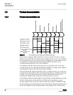
Summary of Contents for Relion 620 Series

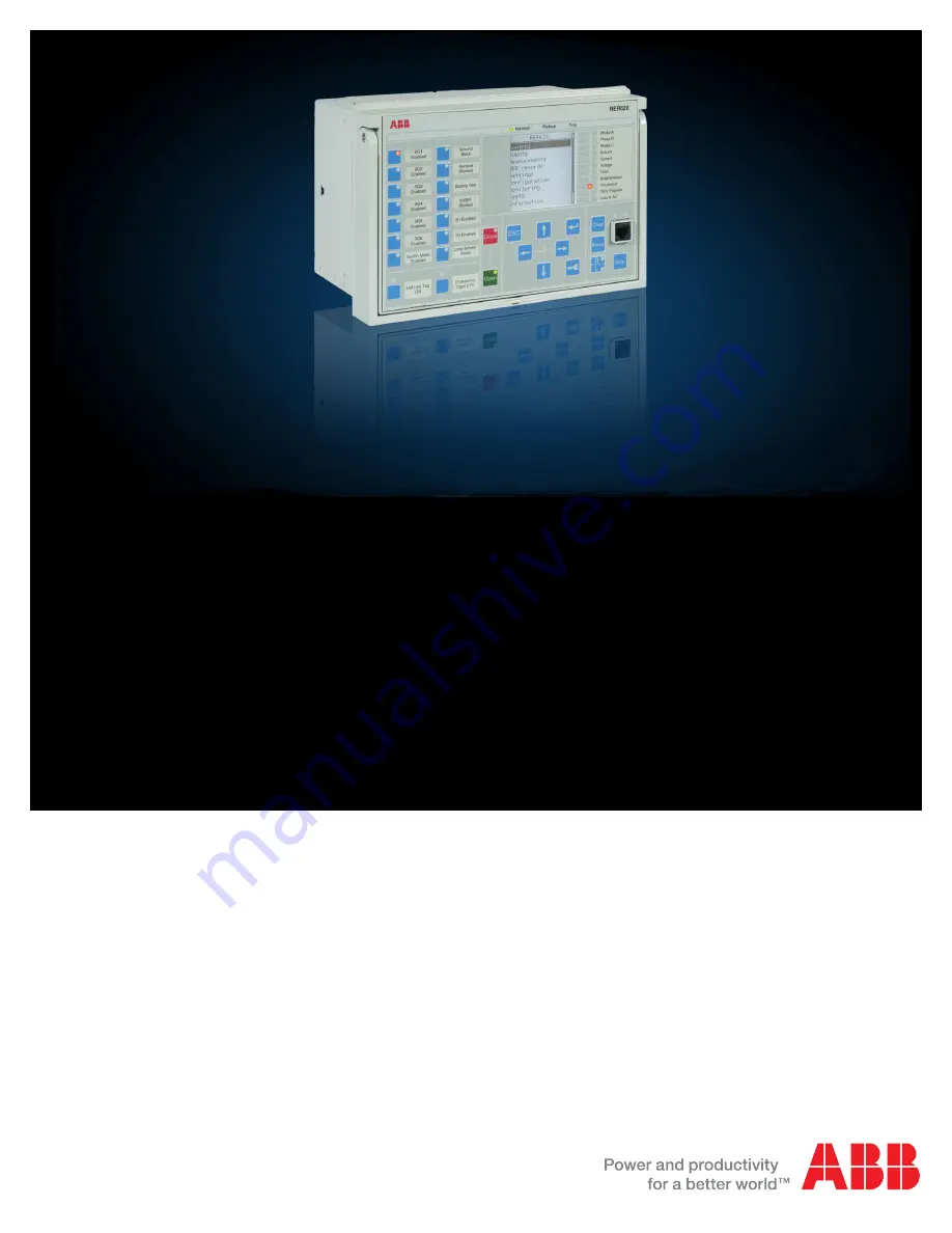
Page 1: ...Relion 620 series Advanced Recloser Protection and Control RER620 Application Manual...

Page 2: ......

Page 3: ...Document ID 1MAC308145 MB Issued 7 20 2017 Revision E Product version 1 3 Copyright 2017 ABB All rights reserved...

Page 4: ...osed only in accordance with the terms of such license Trademarks ABB and Relion are registered trademarks of ABB Group All other brand or product names mentioned in this document may be trademarks or...

Page 5: ...roduct failure would create a risk for harm to property or persons including but not limited to personal injuries or death shall be the sole responsibility of the person or entity applying the equipme...

Page 6: ...lectrical equipment for use within specified voltage limits Low voltage directive 2006 95 EC This conformity is the result of tests conducted by ABB in accordance with the product standards EN 50263 a...

Page 7: ...600 and relay connectivity package version 11 Physical hardware 12 Local HMI 14 LCD 15 LEDs 15 Keypad 15 Web HMI 16 Authorization 17 Communication 18 Section 3 RER620 application 21 Applications 21 Fu...

Page 8: ...etting DLCM Function 67 Hot Line Tag Functionality 67 Section 4 Requirements for measurement transformers 71 Current transformers 71 Current transformer requirements for non directional overcurrent pr...

Page 9: ...find out when and for what purpose a typical protection function can be used The manual can also be used when calculating settings 1 2 Intended audience This manual addresses the protection and contro...

Page 10: ...tion manual contains instructions on how to operate the relay once it has been commissioned The manual provides instructions for monitoring controlling and setting the relay The manual also describes...

Page 11: ...nt revision date Product version History A 11 23 2010 1 0 First release B 10 31 2011 1 1 Content updated to correspond to the product series version C 08 14 2014 1 2 Content updated to correspond to t...

Page 12: ...in italics for example The function can be enabled and disabled with the Operation setting Parameter values are indicated with quotation marks for example The corresponding parameter values are Enabl...

Page 13: ...rcurrent protection with 1 ph trip option SPHIPTOC1 3I 1 50P 3 Non directional time overcurrent ground fault protection low stage XEFLPTOC2 Io 2 51N Non directional time overcurrent ground fault prote...

Page 14: ...on source1 ROVPTOV1 Uo 1 59N 1 Zero sequence overvoltage protection source 2 ROVPTOV2 Uo 2 59N 2 Frequency Protection Underfrequency Overfrequency Frequency rate of change Source 1 Stage 1 FRPFRQ1 f f...

Page 15: ...SPCGGIO1 SPCGGIO1 SPCGGIO1 Generic control points 16 outputs SPCGGIO2 SPCGGIO2 SPCGGIO2 Set reset flip flops 8 outputs SRGAPC1 SRGAPC1 SRGAPC1 Set reset flip flops 8 outputs SRGAPC2 SRGAPC2 SRGAPC2 Ti...

Page 16: ...Section 1 1MAC308145 MB E Introduction 10 RER620 Application Manual...

Page 17: ...ion networks The relay is also used as back up protection in applications where an independent and redundant protection system is required The 620 series relays support a range of communication protoc...

Page 18: ...d graphics X100 PSMxxxx Auxiliary power BO module 24 60V DC 2 normally open PO contacts 2 normally closed SO contacts 2 double pole PO contacts with TCS 1 dedicated internal fault output contact X105...

Page 19: ...ion Manual The connection diagrams of different hardware modules are presented in this manual The optional BIO module can be added in the relay to all standard configurations See the installation manu...

Page 20: ...n 2 3 Local HMI Figure 3 LHMI The LHMI of the relay contains the following elements Display Buttons LED indicators Communication port The LHMI is used for setting monitoring and controlling Conf Analo...

Page 21: ...1 matrix programmable alarm LEDs on front of the LHMI The LEDs can be configured with PCM600 and the operation mode can be selected with the LHMI WHMI or PCM600 There are two additional LEDs which are...

Page 22: ...tons and RJ 45 communication port 2 4 Web HMI The WHMI enables the user to access the relay via a web browser The supported web browser versions are Internet Explorer 9 0 10 0 and 11 0 WHMI offers sev...

Page 23: ...of the WHMI The WHMI can be accessed locally and remotely Locally by connecting your laptop to the relay via the front communication port Remotely over LAN WAN 2 5 Authorization The user categories ha...

Page 24: ...elay can send and receive binary signals from other relays so called horizontal communication using the IEC61850 8 1 GOOSE profile where the highest performance class with a total transmission time of...

Page 25: ...s except for the front port connector are placed on integrated communication modules The relay can be connected to Ethernet based communication systems via the RJ 45 connector 100BASE TX or the fiber...

Page 26: ...Section 2 1MAC308145 MB E RER620 overview 20 RER620 Application Manual...

Page 27: ...guration RA01 RA02 and is delivered from the factory with the default settings and parameters The functional diagrams shown in this section describes the full functionality flexibility and external co...

Page 28: ...tion PDNSPTOC1 I2 I1 46PD Three phase inrush detector INPHAR 3I2f INR Directional Protection Single phase directional overcurrent protection low stage 1 SDPHLPDOC1 3I 1 67 51P 1 Single phase direction...

Page 29: ...1 is defined as bus Source 2 as line SECRSYN1 SYNC 25 Circuit Breaker 1 3 state inputs 3 control outputs SCBXCBR1 I O CB 52 Loop control DLCM LCM LCM Supervision and Monitoring CB condition monitorin...

Page 30: ...8 timers TOFGAPC2 TOFGAPC2 TOFGAPC2 Time delay on timers 8 timers TONGAPC1 TONGAPC1 TONGAPC1 Time delay on timers 8 timers TONGAPC2 TONGAPC2 TONGAPC2 Multipurpose generic up down counter UDFCNT1 UDFC...

Page 31: ...available and option selected Table 9 Programmable buttons and functional selection 1 8 left column in the relay Programmable buttons area LED Label LED 1 Phase A LED 2 Phase B LED 3 Phase C LED 4 Gr...

Page 32: ...y Programmable buttons area Programmable Button Functional Selection Toggle Button 9 Ground Blocked On Off Toggle Button 10 Re close Blocked On Off Toggle Button 11 Battery Test Toggle Button 12 50SEF...

Page 33: ...URP WHUQDO 97 RLO 3K ORVH 7ULS RLO 3K ORVH 7ULS 2UGHU 6HOHFWDEOH 2SWLRQDO 1 DVH 5 5 7 7 1 VRODWHG URXQG 5 5 5 1 75 7 5 5 576 7 76 7 2SWLFDO 67 DVH RU DVH7 5 5 9 URP WHUQDO 97 9 URP WHUQDO 97 9 URP 5H...

Page 34: ...onal BIO modules RER620 X110 16 14 15 19 17 18 22 20 21 SO3 SO2 SO1 24 23 SO4 X105 16 14 15 19 17 18 22 20 21 SO3 SO2 SO1 24 23 SO4 1 1 1 Order Selectable Optional X110 1 2 5 6 7 8 9 10 BI 6 BI 5 BI 4...

Page 35: ...d connections to the different function blocks inside the relay s default configuration RER620 offers six different settings group which the user can set based on individual needs Each group can then...

Page 36: ...B1 B2 O OR B1 B2 O NOT IN OUT TONGAPC2 IN1 IN2 IN3 IN4 IN5 IN6 IN7 IN8 Q1 Q2 Q3 Q4 Q5 Q6 Q7 Q8 UDFCNT10 UP_CNT DOWN_CNT RESET LOAD UPCNT_STS DNCNT_STS NOT IN OUT AND B1 B2 O AND B1 B2 O R_TRIG CLK Q...

Page 37: ...is selected Otherwise all three phases are tripped and the related outputs Trip Operate and pickup Start are activated The overcurrent protection function picks up when the phase current exceeds the...

Page 38: ...TOC1_50P 3_OPERATE SPHLPTOC2_50P 1_OPERATE SPHHPTOC1_50P 2_OPERATE SPHLPTOC1_51P_OPERATE INRPHAR1_INR_BLK2H SPCGGIO1_O7_SWITCH_MODE SPCGGIO1_O7_SWITCH_MODE SPCGGIO1_O7_SWITCH_MODE SDARREC1_79_PROT_CRD...

Page 39: ...phase fault etc The phase discontinuity protection 46PD provides protection for interruptions in the normal three phase load supply like in downed conductor situations The sensitive earth fault prote...

Page 40: ...B2 B3 B4 B5 B6 O AND6 B1 B2 B3 B4 B5 B6 O NOT IN OUT OR6 B1 B2 B3 B4 B5 B6 O AND6 B1 B2 B3 B4 B5 B6 O NOT IN OUT AND6 B1 B2 B3 B4 B5 B6 O NOT IN OUT XNSPTOC2_46 2_OPERATE PDNSPTOC_46PD_OPERATE XNSPTOC...

Page 41: ...AND B1 B2 O OR B1 B2 O OR6 B1 B2 B3 B4 B5 B6 O AND6 B1 B2 B3 B4 B5 B6 O NOT IN OUT AND B1 B2 O UNBALANCE_PROT X115_UPD_Input1 X115_UPD_Input1 X115_UPD_Input2 X115_UPD_Input2 X115_UPD_Input3 X115_UPD_...

Page 42: ..._INST1_TRIP SPCGGIO1_O9_GND_BLOCK SPCGGIO1_O9_GND_BLOCK SPCGGIO1_O9_GND_BLOCK SPCGGIO1_O9_GND_BLOCK XEFHPTOC3_50N 2_OPERATE XEFLPTOC3_50N 1_OPERATE XEFIPTOC2_50N 3_OPERATE XEFLPTOC2_51N_OPERATE INRPHA...

Page 43: ...B5 B6 O OR6 B1 B2 B3 B4 B5 B6 O OR B1 B2 O SPCGGIO1_O9_GND_BLOCK SPCGGIO1_O12_50SEF_BLOCK EFLPTOC3_50SEF_OPERATE INRPHAR1_INR_BLK2H SPCGGIO1_O7_SWITCH_MODE EFLPTOC3_50SEF_BLOCK_IN3 NEUTRAL_PROT_BLOCK...

Page 44: ...IN1 IN2 OUT1 OUT2 OR6 B1 B2 B3 B4 B5 B6 O OR B1 B2 O OR B1 B2 O OR B1 B2 O OR B1 B2 O OR B1 B2 O OR B1 B2 O NOT IN OUT AND B1 B2 O SPHLPTOC2_50P 1_BLOCK XEFLPTOC3_50N 1_BLOCK EFLPTOC3_50SEF_BLOCK_IN3...

Page 45: ...RIP_C PICKUP_A PICKUP_B PICKUP_C XDEFLPDEF1 67 5 BLOCK ENA_MULT RCA_CTL TRIP PICKUP XDEFLPDEF2 67 5 BLOCK ENA_MULT RCA_CTL TRIP PICKUP OR B1 B2 O OR B1 B2 O SDPHLPDOC1_67 51P 1_OPERATE SDPHLPDOC1_67 5...

Page 46: ..._C_CA PICKUP PU_A_AB PU_B_BC PU_C_CA SPHPTUV1 27 1 3 BLOCK TRIP TRP_A_AB TRP_B_BC TRP_C_CA PICKUP PU_A_AB PU_B_BC PU_C_CA SPHPTUV2 27 2 3 BLOCK TRIP TRP_A_AB TRP_B_BC TRP_C_CA PICKUP PU_A_AB PU_B_BC P...

Page 47: ..._OPERATE SPHPTUV3_27 3_OPERATE ROVPTOV1_59N 1_OPERATE NSPTOV2_47 2_OPERATE PSPTOV2_59PS 2_OPERATE PSPTOV1_59PS 1_OPERATE SPHPTOV3_59 3_OPERATE FRPFRQ2 81 2 f BLOCK TRIP OPR_OFRQ OPR_UFRQ OPR_FRG PICKU...

Page 48: ...B2 O OR B1 B2 O OR B1 B2 O OR B1 B2 O OR6 B1 B2 B3 B4 B5 B6 O OR6 B1 B2 B3 B4 B5 B6 O TRIP_FAIL_SET SCCBRBRF1_50BF_TRBU SDAOGGIO1_79 OUT_OPEN_CB_A SDAOGGIO1_79 OUT_OPEN_CB_B SDAOGGIO1_79 OUT_OPEN_CB_C...

Page 49: ...NOT IN OUT AND B1 B2 O AND6 B1 B2 B3 B4 B5 B6 O NOT IN OUT TRIP_FAIL_ALARM SCBXCBR1_52_EXE_CL_3P SCBXCBR1_52_EXE_CL_A SCBXCBR1_52_EXE_CL_B SCBXCBR1_52_EXE_CL_C PH_ORD_OUT_X115_CL_IN1_A PH_ORD_OUT_X11...

Page 50: ...ibution system The LCM enables a recloser to monitor up to two banks of three phase voltages and to consider them in controlling breaker operations A recloser loop control scheme typically utilizes a...

Page 51: ...B3 B4 B5 B6 O OR B1 B2 O OR B1 B2 O OR B1 B2 O OR B1 B2 O KEY_16_EMERGENCY_OPEN SDAOGGIO1_79 OUT_LOCKED_A SDAOGGIO1_79 OUT_LOCKED_B SDAOGGIO1_79 OUT_LOCKED_C SDAOGGIO1_79 OUT_LOCKED_3P X115_UPD_Input1...

Page 52: ...6 B1 B2 O OR O 37 T 2 5 I 30 B1 B2 O OR6 O 34 T 2 5 I 43 B1 B2 B3 B4 B5 B6 O OR6 O 35 T 2 5 I 42 B1 B2 B3 B4 B5 B6 O SCBXCBR1_52_EXE_OP_3P SCBXCBR1_52_EXE_CL_3P SDAOGGIO1_79 OUT_LOCKED_A SDAOGGIO1_79...

Page 53: ...C_OK CL_FAIL_AL CMD_FAIL_AL LLDB LLLB DLLB DLDB AND B1 B2 O NOT IN OUT OR B1 B2 O SEQRFUF1_60_FUSEF_U SECRSYN1_25_SYNC_OK SPCGGIO2_25_BLK SPCGGIO2_25_BLK SECRSYN1_25_SYNC_INPRO Note In synch check fun...

Page 54: ...ossible The Latched Open state can be de activated by the same push button after a minimal interval of 5 seconds The Figure 31 shows the Auto reclose function with Latched Open as one of the input cha...

Page 55: ...O OR B1 B2 O SCBXCBR1_52_EXE_CL_A SCBXCBR1_52_EXE_CL_B SCBXCBR1_52_EXE_CL_C SDAOGGIO1_79 OUT_OPEN_CB_A SDAOGGIO1_79 OUT_OPEN_CB_B SDAOGGIO1_79 OUT_OPEN_CB_C SCBXCBR1_52_EXE_OP_A SCBXCBR1_52_EXE_OP_B S...

Page 56: ...1_CL_PH_A X115_UPD_IN2_CL_PH_B X115_UPD_IN3_CL_PH_C SPSCBR1 52CM CB BLOCK POSOPEN_A POSOPEN_B POSOPEN_C POSCLOSE_A POSCLOSE_B POSCLOSE_C PRES_ALM_IN PRES_LO_IN SPR_CHR_ST SPR_CHR RST_IPOW RST_CB_WEAR...

Page 57: ...H_x inputs of all phases for SCBXCBR function in Figure 27 UDFCNT1 UDFCNT1 UP_CNT DOWN_CNT RESET LOAD UPCNT_STS DNCNT_STS UDFCNT4 UDFCNT4 UP_CNT DOWN_CNT RESET LOAD UPCNT_STS DNCNT_STS UDFCNT2 UDFCNT2...

Page 58: ...1 B2 B3 B4 B5 B6 O OR6 B1 B2 B3 B4 B5 B6 O NOT IN OUT OR6 B1 B2 B3 B4 B5 B6 O LED6_VOLTAGE_OPERATE LED5_CURRENT_OPERATE TRIP_FAIL_SET HOTLINE_TAG LATCHED_OPEN DLCM1_LCM_TRIP PH_ORD_OUT_SCBXCBR1_OP_OUT...

Page 59: ...sources The two sources can be from the recloser and the external voltage transformer This block also generates the high alarm warning and low alarm warning signal based on the preset levels Figure 3...

Page 60: ...ion 54 RER620 Application Manual Figure 38 Power measurement The FMMXU block measures the frequency of the analog inputs to the RER620 The value measured is displayed in Hertz Figure 39 Frequency meas...

Page 61: ...HLPTOC1_51P_OPERATE XEFIPTOC2_50N 3_OPERATE XEFLPTOC2_51N_OPERATE XNSPTOC2_46 2_OPERATE PDNSPTOC_46PD_OPERATE XNSPTOC1_46 1_OPERATE SDPHLPDOC1_67 51P 1_OPERATE SDPHLPDOC1_67 51P 2_OPERATE XDEFLPDEF1_6...

Page 62: ...UT_START OUT_OPERATE OUT_ST_A OUT_OPR_A OUT_ST_B OUT_OPR_B OUT_ST_C OUT_OPR_C OUT_ST_NEUT OUT_OPR_NEUT OR B1 B2 O LED8_INST_TRIP LED8_INST1_TRIP LED9_RECL_LOCKOUT LED11_AC_LOSS LED6_VOLTAGE_OPERATE LE...

Page 63: ...eous operations two time delayed operation and lockout on the A phase pole Since the fault is a permanent single phase to ground fault e g A N the load connected to A phase will experience an outage b...

Page 64: ...this pickup and initiate a binary output signal from the RER620 to the recloser the recloser will trip open phase B and await timing from the RER620 for subsequent reclose or lockout Now suppose that...

Page 65: ...However we still have three actuators and three position sensors for the three poles so the controls must operate independently However for any fault the trip reclose lockout signals are issued to all...

Page 66: ...irst part of the function Outputs from the function consist of per phase breaker open close commands and lockout signals 3 4 3 Input function blocks SDAIGGIOs The input section consists of six modular...

Page 67: ...OC2_50P 1_START_A SPHLPTOC2_50P 1_START_B SPHLPTOC2_50P 1_START_C SPHHPTOC1_50P 2_START_A SPHHPTOC1_50P 2_START_B SPHHPTOC1_50P 2_START_C SPHIPTOC1_50P 3_START_A SPHIPTOC1_50P 3_START_B SPHIPTOC1_50P...

Page 68: ...gnals to the phases that are active for the reclose cycle in progress currently Also actual breaker status of individual pole are connected as input channels for SDAOGGIO function block in the applica...

Page 69: ...type of reclosers Sectionalizing reclosers Midpoint reclosers TiePoint recloser An explanation of the function of each of these reclosers types is given in the section below 3 5 1 Sectionalizing Reclo...

Page 70: ...s reset 3 5 4 DLCM Function Block The Loop Control Module DLCM function is configured in RER620 as a part of its default configuration as shown in Figure 46 Figure 46 DLCM Function in ACT configuratio...

Page 71: ...ine setting is selected with number of voltage transformers connected If the Vt config line is 1 or 2 the Vt line phase setting is selected as the phase to which the voltage transformers is connected...

Page 72: ...de the SET_GROUP_CHANGE is activated and SWOTF output is activated for a time of SWOTF time setting if the status of the phases selected is dead and if En set grp chg setting is TRUE Figure 49 Group c...

Page 73: ...All the restoration steps should be performed before in full compliance with all applicable safety procedures before resetting the DLCM functionality in RER620 relay 3 6 Hot Line Tag Functionality The...

Page 74: ...he application configuration logic scheme is shown in figure below L_Flag or R_Flag represents the HLT function status which can be activated and deactivated locally through pushbutton 8 Key 8 Figure...

Page 75: ...CGGIO1_O6 DLCM1_LCM_RESET_OUT DLCM1_LCM_S2_EN DLCM1_LCM_S1_EN ZBAT1_TST_RESULT HOTLINE_TAG KEY_8 SPCGGIO1_O10_RECLOSE_BLOCK SPCGGIO1_O9_GND_BLOCK SPCGGIO1_O12_50SEF_BLOCK KEY_16_EMERGENCY_OPEN SPCGGIO...

Page 76: ...K_CLOSE_PH_B BLK_CLOSE_PH_C ITL_BYPASS_PH_A ITL_BYPASS_PH_B ITL_BYPASS_PH_C AU_OPEN_A AU_OPEN_B AU_OPEN_C AU_OPEN_3P AU_CLOSE_A AU_CLOSE_B AU_CLOSE_C AU_CLOSE_3P OPENPOS_A OPENPOS_B OPENPOS_C CLOSEPOS...

Page 77: ...ated accuracy limit factor Fn is the ratio of the rated accuracy limit primary current to the rated primary current For example a protective current transformer of type 5P10 has the accuracy class 5P...

Page 78: ...put of the relay For that reason in practice even a few times smaller nominal primary current can be used than given by the formula Recommended pickup current settings If Ikmin is the lowest primary c...

Page 79: ...rent should not saturate the CT less than 20 times the pickup current Otherwise the inverse operation time can be further prolonged Therefore the accuracy limit factor Fa should be chosen using the fo...

Page 80: ...ngs for all three stages are as in the figure above For the application point of view the suitable setting for instantaneous stage 50P 3 in this example is 3 500 A 5 83 x I2n For the CT characteristic...

Page 81: ...ry voltage of the relay is connected to terminals X100 1 2 At DC supply the positive lead is connected to terminal X100 1 The permitted auxiliary voltage range is 24 60 VDC Table 15 Auxiliary voltage...

Page 82: ...odules can be included in slots 105 and 110 Each BIO module includes eight input terminals Table 16 Input terminals for BIO module in X105 X110 slot 1 13 Table 17 Binary Input terminals X120 1 6 Termi...

Page 83: ...lot X100 or SO1 SO2 SO3 and SO4 in slot X105 X110 optional can be used for signaling on pickup and tripping of the relay On delivery from the factory the pickup and alarm signals from all the protecti...

Page 84: ...ed X100 3 5 When a fault is detected by the self supervision system or the auxiliary voltage is disconnected the output contact drops off and the contact closes X100 3 4 Table 21 IRF contact Terminal...

Page 85: ...iption X115 1 Not connected 3 3V DC X115 2 RS 485 From UPS X115 3 RS 485 From UPS X115 4 RS 485 Common 15V DC X115 5 Not connected 15V DC X115 6 250V DC Boost from UPS X115 7 250V DC Boost to Cap X115...

Page 86: ...Section 5 1MAC308145 MB E Relay physical connections 80 RER620 Application Manual...

Page 87: ...category 5 or higher with RJ 45 connectors ACT Application configuration tool AIM Analog input module ANSI American National Standards Institute BI Binary input BI O Binary input output BO Binary outp...

Page 88: ...diode LHMI Local human machine interface Modbus A serial communication protocol developed by the Modicon company in 1979 Originally used for communication in PLCs and RTU devices MV Medium voltage PCM...

Page 89: ......

Page 90: ...stribution Automation 4300 Coral Ridge Drive Coral Springs FL 33065 USA Phone 1 800 523 2620 Phone 1 954 752 6700 Fax 1 954 345 5329 www abb com substationautomation 1MAC308145 MB E Copyright 2017 ABB...

Reviews: