

—
INTRODUCTION
This document explains how to install the plug-in
ABB OVR Surge Protective Devices (SPDs) for
telephone and ISDN lines:
OVR TN/RJ11-2/6
protects the middle 2 (of 6) conductors on
telephone lines with RJ11 connections.
OVR TN/RJ11-4/6
protects the middle 4 (of 6) conductors on
telephone lines with RJ11 connections.
OVR TN/RJ11-6/6
protects all 6 conductors on telephone lines with
RJ11 connections.
OVR ISDN/RJ45-4/8
protects the middle 4 (of 8) conductors on S/T
interface ISDN lines with RJ45 connections.
OVR ISDN/RJ45-8/8
protects all 8 conductors on S/T interface ISDN
lines with RJ45 connections.
2. Before installation
2.1 Make sure that the system’s maximum line
voltage (DC or AC peak) will never exceed the
maximum working voltage of the SPD.
Otherwise the SPD will clamp signal voltages
as though they were transient overvoltages.
Maximum Working
Voltage
OVR TN/RJ11
296 V
OVR ISDN/RJ45
58 V
2.2 Make sure that the SPD’s plug and socket
connections are physically compatible with
those connecting the equipment to the
telephone (or ISDN) line.
2.3 Ensure that the current passing through the
SPD does not exceed 300 mA.
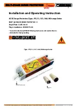
3. Installation
3.1 Connection
The SPD is connected in series with the
telephone (or ISDN) line (see Figures 1 and 2).
If the SPD’s dirty line cable is longer than
required, neatly coil and bind the surplus out
of the way, keeping this away from clean
cables.
3.4 Earthing
The SPD must be connected to a good
electrical earth, either:
a) through installation on a TS36 'top hat' DIN
rail (which in turn is connected to earth), or
b) by connecting a crimped 10mm² stranded
green/yellow cable should be used to bond
the SPD’s earth stud to earth.
This SPD earth bond should be less than
1 metre long (otherwise the effectiveness of
the SPD will be reduced).
Ideally the SPD would be connected to the
main electrical earth or earth star point
(located at a distribution board) (see Figure
4, overleaf).
However, owing to the 1 metre (maximum)
earth bond, the SPD will often be hard-wired
to the ring main earth.
Never connect the SPD to earth via the earth
pin of a plug, as this may be removed.
If the earth bond is more than 1 metre from
the SPD, earth bonds of 2, 3 or 4 metres are
allowed if 2, 3 or 4 parallel earth bonds are
used. These must be kept at least 5 cm apart
from each other.
The SPD or base plate earth bond should be
less than 1 metre long (otherwise the
effectiveness of the SPD will be reduced).
10 mm² stranded green/yellow cable should
be used for this bond.
SPD or base plate earth bonds of 2, 3 or
4 metres are allowed if:
– 2, 3 or 4 parallel earth bonds are used and
– these parallel earth bonds are kept at
least 5 cm apart from each other
Where even 4 metres of connecting lead is
not sufficient, the incoming cable should be
re-routed to bring it within 4 metres of the
earth.
In circumstances where the cable cannot
ideally be re-routed, the SPD can alternatively
be connected to the electrical earth local to
the equipment being protected (eg the earth
bar of the local power distribution board)
(see Figure 4).
... continued overleaf
1. Safety note:
Warning! Installation by person with
electrotechnical expertise only.
Warnung! Installation nur durch
elektrotechnische Fachkraft.
Avvertenza! Fare installare solo da un
elettricista qualificato.
Avertissement! Installation uniquement par
des personnes qualifiées en électrotechnique.
Advertencia! La instalación deberá ser
realizada únicamente por electricistas
especializados.
A protector on the mains power supply to
equipment is also recommended in addition to
protection on telephone & ISDN lines.
Simply plug it into the telephone socket and
plug the protected equipment into the SPD.
Note: The mains power input to equipment
should also be protected.
3.2 Mounting
Fixing holes on the base of the unit enable it
to be screwed to any flat surface.
Before doing so, ensure that it is close to a
good earthing point (see Section 3.4
- Earthing).
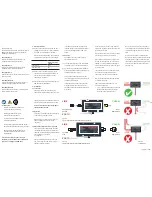
3.3 Keep clean cables away from dirty cables
The outgoing clean cable (ie from the SPD’s
socket end) should never be routed next to
the incoming dirty line cable (the SPD's cable
end) or the dirty earth cable
(see Figure 3).
The clean cable must be kept at least 5 cm
apart from either the SPD’s dirty cable, or
those of neighbouring units.
ELECTRONIC SYSTEMS PROTECTION
Plug-in Lightning Barrier
Wilford Road,
Nottingham,
NG2 1EB, UK
LINE
CLEAN
To ISDN
Line
From
Equipment
EARTH
ELECTRONIC SYSTEMS PROTECTION
Plug-in Lightning Barrier
Wilford Road,
Nottingham,
NG2 1EB, UK
Figure 1:
Plug-in series connection for OVR TN/RJ11-2/6, 4/6 and 6/6.
LINE
CLEAN
To Telephone
Socket
From
Equipment
EARTH
ELECTRONIC SYSTEMS PROTECTION
Plug-in Lightning Barrier
Wilford Road,
Nottingham,
NG2 1EB, UK
ELECTRONIC SYSTEMS PROTECTION
Plug-in Lightning Barrier
Wilford Road,
Nottingham,
NG2 1EB, UK
ELECTRONIC SYSTEMS PROTECTION
Plug-in Lightning Barrier
Wilford Road,
Nottingham,
NG2 1EB, UK
ELECTRONIC SYSTEMS PROTECTION
Plug-in Lightning Barrier
Wilford Road,
Nottingham,
NG2 1EB, UK
ELECTRONIC SYSTEMS PROTECTION
Plug-in Lightning Barrier
Wilford Road,
Nottingham,
NG2 1EB, UK
ELECTRONIC SYSTEMS PROTECTION
Plug-in Lightning Barrier
Wilford Road,
Nottingham,
NG2 1EB, UK
Installation Instructions for Mains Wire-In Protectors |
1
Safety note:
Warning! Installation by person with
electrotechnical expertise only.
Warnung! Installation nur durch
elektrotechnische Fachkraft.
Avvertenza! Fare installare solo da un
elettricista qualificato.
Avertissement! Installation uniquement par
des personnes qualifiées en électrotechnique.
Advertencia! La instalación deberá ser
realizada únicamente por electricistas
especializados.
ESP protector installation should be
conducted by a qualified competent person
and comply with all relevant Regulations and
Legislation (including BS 7671 Wiring
Regulations and Building Regulations).
Incorrect installation will impair the
effectiveness of ESP protectors.
Always handle cables by their insulation.
Never work on ESP protectors, earthing or
their cables during a storm.
1. Key points of installation
1.1 Install protectors very close to the power
supply to be protected, either within the
distribution panel or directly alongside it.
1.2 Mount units within a panel or WBX
enclosure.
1.3 Units are installed in parallel.
1.4 Connect to phase(s), neutral and earth.
NOTE: Units must have a neutral
connection (see 3.4).
1.5 Units installed at power distribution
boards can be installed either:
-
on the load side of the incoming
isolator
-
on the closest available out going way to
the incoming supply
1.6 Provide a means of isolation for the
ESP unit.
1.7 The connecting leads to phase/live
terminals should be suitably fused
(up to 125 Amps) ensuring full
discrimination with the immediate
upstream supply fuse.
1.8 Connecting leads should be 10 mm
2
multi-stranded copper conductor
(terminals can accept up to 25 mm
2
).
1.9 Keep the connecting leads as short as
possible and ideally less than 25 cm
(10 inches) in length. This may be better
achieved with the equivalent M1R
remote display variant which permits
optimum positioning of both protector
and display.
1.10 Bind the connecting leads tightly
over their entire length.
1.11 Maximum torque for power terminals is
2.9Nm, wire stripping length 17mm.
1.12 Maximum torque for remote contact is
0.25Nm, wire stripping length 7mm.
1
Installation instructions
ESP M1/M1R mains protectors
Figure 2:
Plug-in series connection for OVR ISDN/RJ45-4/8 and 8/8.
Figure 3:
Cable routeing.