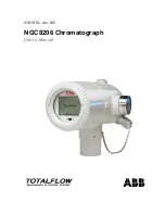
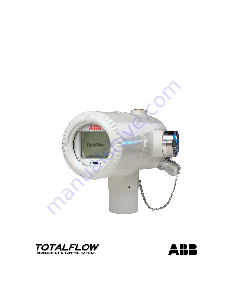
background image

2101510– rev. AG 

NGC8206 Chromatograph 

User’s Manual 

Summary of Contents for NGC8206

Page 1: ...2101510 rev AG NGC8206 Chromatograph User s Manual ...

Page 2: ...ish version will be considered final Notice This publication is for information only The contents are subject to change without notice and should not be construed as a commitment representation warranty or guarantee of any method product or device by Owner Inquiries regarding this manual should be addressed to ABB Inc Totalflow Products Technical Communications 7051 Industrial Blvd Bartlesville Ok...

Page 3: ...stem Specifications 2 5 2 3 1 NGC8206 Standard Hardware Features 2 6 2 3 2 Recommended Spare Parts 2 7 2 3 3 Cast Aluminum Enclosure 2 7 2 3 4 Feed through Assembly 2 9 2 3 5 Analytical Module 2 10 2 3 6 Digital Controller Assembly with VGA Display 2 14 2 3 7 Termination Panel 2 16 2 4 Grounding the NGC 2 17 2 4 1 Power Supply 2 18 2 4 2 Sample Probe 2 18 2 4 3 Other Considerations 2 18 2 5 Calibr...

Page 4: ...28 2 13 5 Audit Logs 2 29 2 14 TCR Sample Probe Optional Equipment 2 29 2 14 1 Location 2 30 2 14 2 Other Considerations 2 30 2 15 Environmental Enclosure Optional Equipment 2 30 2 15 1 Standard Features 2 30 2 15 2 Optional Features 2 33 2 16 Sample Conditioning Modules Optional Equipment 2 33 2 16 1 Gas Types 2 34 2 16 2 Mounting Brackets 2 35 2 17 Security Seal Optional Equipment 2 37 2 17 1 Cu...

Page 5: ...tion 3 9 3 7 Large Pipe Mounted Environmental Enclosure Mounting Kit 3 11 3 7 1 Materials 3 11 3 7 2 Installation 3 11 3 8 Optional Support Leg Kit Installation 3 14 3 8 1 Materials 3 14 3 8 2 Instructions 3 14 3 9 Small Pipe Mounted Environmental Enclosure Mounting Kit 3 15 3 9 1 Materials 3 15 3 9 2 Installation 3 15 3 10 Pipe Saddle Installation 3 18 3 10 1 Material Not Supplied 3 18 3 10 2 Ins...

Page 6: ... Regulator Installation 3 41 3 22 1 Materials 3 41 3 22 2 Instructions 3 41 3 23 Carrier Gas and Calibration Gas Connections 3 43 3 23 1 Materials 3 43 3 23 2 Instructions 3 43 3 24 Vent Lines Connections 3 45 3 24 1 Materials 3 45 3 24 2 Instructions 3 45 3 25 ENC82L Optional Catalytic Heater Installation 3 46 3 25 1 Materials 3 46 3 25 2 Instructions 3 46 3 26 ENC82S Optional Catalytic Heater In...

Page 7: ...er Installation 3 77 3 37 1 Instructions 3 77 3 38 Remote Communication Installation 3 77 4 0 NGC8206 STARTUP 4 1 4 1 PCCU32 Installation and Setup 4 1 4 1 1 Software Installation Instructions 4 1 4 2 Ethernet Installation and Setup 4 2 4 2 1 TCP IP Network Connection 4 2 4 2 2 TCP IP Local Connection 4 4 4 3 Connecting to the NGC8206 Local Port 4 5 4 3 1 Communicate Instructions 4 5 4 4 NGC Diagn...

Page 8: ...ctory Defaults 5 9 5 8 1 Instructions 5 10 5 9 Lithium Battery Status 5 10 5 9 1 Instructions 5 10 5 10 Changing NGC Clock 5 11 5 10 1 Clock Change Not Crossing a Log Period Boundary 5 11 5 10 2 Forward Clock Change Crossing a Log Period Boundary 5 11 5 10 3 Backward Clock Change Crossing a Log Period Boundary 5 11 5 11 Replacing Calibration or Carrier Gas Bottle s 5 11 5 11 1 Instructions 5 12 5 ...

Page 9: ...rity 6 8 6 3 3 Pressure Regulator 1 or 2 Alarm 6 8 6 3 4 Sample Pressure Alarm 6 9 6 3 5 Oven Temperature Error Alarm 6 10 6 3 6 No Stream Valve Selected 6 11 6 3 7 Digital Analog Board Communication Error Alarm 6 11 6 3 8 Calculation Error Alarm 6 12 6 3 9 Calibration Un Normalized Error Alarm 6 12 6 3 10 Stream Sequence Error Alarm 6 13 6 3 11 Calibration CV Percent Error Alarm 6 13 6 3 12 Calib...

Page 10: ...uipment Isolation Test 6 24 6 5 4 NGC Module Isolation Test 6 25 6 5 5 Charger Circuit Test 6 26 6 5 6 Solar Panel Troubleshooting Test 6 27 6 5 7 AC Charger Power Supply Troubleshooting Test 6 28 6 6 Troubleshooting Communications 6 28 6 6 1 Communication 6 29 6 6 2 Setting Up Communication 6 29 6 6 3 Transceiver Supply Voltage Test 6 31 6 6 4 12 VDC Communication Supply Voltage Test 6 31 6 6 5 T...

Page 11: ...tic Heater 2 32 Figure 2 22 ENC82S Environmental Enclosure with Electric Heater 2 32 Figure 2 23 ENC82S Environmental Enclosure with Catalytic Heater 2 33 Figure 2 24 Available Sample Conditioning Modules 2 34 Figure 2 25 Single and Multiple Stream Sample Conditioning Assemblies 2 35 Figure 2 26 Single Stream Conditioning Module Dimensions 2 36 Figure 2 27 Multiple Stream Conditioning Module Dimen...

Page 12: ...structions 3 34 Figure 3 34 Suggested RS 422 Wiring Instructions 3 34 Figure 3 35 Carrier Calibration Gas Bottle Rack Installation 3 35 Figure 3 36 Dual Bottle Rack Assembly 3 36 Figure 3 37 ENC82L Dual Bottle Rack Installation 3 37 Figure 3 38 ENC82S Dual Bottle Rack Installation 3 37 Figure 3 39 Carrier Gas Pressure Regulator with Relief Valve 3 38 Figure 3 40 Carrier Gas Low Pressure Switch Wir...

Page 13: ...th Battery Pack 3 70 Figure 3 74 12 24 VDC Dual Battery Pack Cable 3 70 Figure 3 75 Battery Pack with DC Power Supply Wiring Instructions 3 71 Figure 3 76 Battery Pack with AC Power Supply Wiring Instructions 3 72 Figure 3 77 Typical Solar Panel Installation 3 73 Figure 3 78 12 VDC Battery Pack Solar Panel Wiring Instructions 3 75 Figure 3 79 24 VDC Battery Pack Solar Panel Wiring Instructions 3 7...

Page 14: ...xii Figure 6 3 AC Charger Power Supply Wiring 6 28 Figure 6 4 Communication Troubleshooting Flowchart 6 30 ...

Page 15: ...ompensated Regulator TCR 2 29 Table 2 10 Sample Conditioning Module Descriptions 2 34 Table 3 1 Installation Matrix 3 3 Table 3 2 Port 1 and Port 2 Pin Outs Terminations 3 77 Table 4 1 Station Setup Screen Information 4 7 Table 4 2 Stream Setup Screens 4 8 Table 4 3 Defaulted Alarm Definitions 4 13 Table 5 1 Repair Time vs Down Time 5 5 Table 5 2 Recommended Spare Parts 5 5 Table 5 3 Tool Requirem...

Page 16: ...ocedures for setup and installation 3 Startup Provides the user with a tutorial on how to get a newly installed NGC system up and running 4 Maintenance Provides procedures on how to remove and replace major modules 5 Troubleshooting Provides a troubleshooting chart and procedures on how to correct most problems 1 2 Getting Help At Totalflow we take pride in the on going support we provide our cust...

Page 17: ...ersonal injury if caution is not used Please refer to the Safety Practices and Precaution section Getting Help Intended to draw attention to a statement regarding the likelihood of personal injury or fatality that could result from improper access or techniques used while working in hazardous locations Please refer to the Safety Practices and Precaution section Getting Help Indicates procedures th...

Page 18: ... Removal of enclosure cover s in a hazardous location must follow guidelines stipulated in the certification drawings shipped with this unit If the unit is installed or to be installed in a hazardous location the technician must follow the guidelines stipulated in the certification drawings shipped with this unit Access to a unit via a PCCU cable in a hazardous location must follow guidelines stip...

Page 19: ...Industrial Automation Measurement and Analytics is committed to actively protecting the environment Do not dispose of WEEE as unsorted municipal waste Collect WEEE separately Participation in the management of WEEE is critical to the success of WEEE collection Electrical and electronic equipment marked using the crossed out wheeled bin symbol shall not be mixed with general household waste Correct...

Page 20: ...logy the NGC features a common platform that combines the expandable framework of the XSeries equipment with the capabilities of a remote gas chromatograph This expandability allows the NGC to run other applications such as AGA 3 and AGA 7 while simultaneously doing stream analysis This new platform is designed for operation on Windows CE Real Time Operating System 2 1 2 Calibration Once installed...

Page 21: ...Page 2 2 2101510 Rev AG Figure 2 1 Typical Single Stream Installation INCREASE DECREASE CALIBRATION GAS CARRIER GAS SAMPLE PROBE NGC8200 SAMPLE CONDITIONING MODULE INCREASE DECREASE ...

Page 22: ... SAMPLE PROBE STREAM 1 SAMPLE PROBE NGC8200 SAMPLE CONDITIONING MODULES STREAM 3 SAMPLE PROBE I NCREASE DECREASE CALIBRATION GAS CARRIER GAS For clarity unit is shown mounted on outside meter run For sample line length consideration the unit should be mounted on middle pipe run ...

Page 23: ...one a factor of one is used The processed sample is then vented with the carrier gas and results are stored in memory and communicated to other devices as needed All of these values as well as composition are available on various Modbus communication protocols 2 2 1 Hydrocarbons To further define the natural gas components Table 2 1 gives additional details for each hydrocarbon Among the key infor...

Page 24: ... 100 PPM H2S Analysis Time Approx 5 minutes interval between cycles is adjustable Calibration Validation Streams Up to 2 dedicated reduces sample stream for each dedicated calibration streams Must use dedicated stream s for Auto Cal feature Sample Streams Up to 4 with manual calibration streams Construction NEMA Type 4X IP56 Aluminum Alloy with white polyester powder coating Explosion Proof see sp...

Page 25: ... Weatherproof construction Modular design See Figure 2 3 Digital controller assembly Analytical module with compact design and single bolt replacement Feed through assembly with flame path arrestors Termination panel State of the art electronics 32 bit digital controlling electronics no analog control loops Low power operation Dual digital carrier pressure regulation Digital temperature control Di...

Page 26: ...gh Figure 2 7 shows the outline dimensions of the NGC The end caps have precision engineered threading and are susceptible to damage if treated roughly The enclosure and all fittings including feed through MMI connection and breather are tested to NAME Type 4X Unauthorized removal of the end caps are protected with a 1 16 hex socket set screw on each end cap This enclosure may be pipe mounted on a...

Page 27: ...Page 2 8 2101510 Rev AG Figure 2 4 NGC8206 Enclosure Figure 2 5 NGC8206 Enclosure Left Side ...

Page 28: ...GC8206 Enclosure Underside 2 3 4 Feed through Assembly Independent sample streams are connected to the NGC directly to the feed through assembly see Figure 2 8 or through an optionally installed sample conditioning module The feed through assembly also serves as the connection ...

Page 29: ...edicated auto cal streams or 1 4 sample streams with 1 2 manual calibration streams 1 carrier input stream Figure 2 8 NGC Feed through Assembly 2102026 xxx The 0 5 micron Filters should not be considered as a replacement for the primary filtering system Optional sample conditioning modules are designed for this purpose 2 3 4 2 Vents Feed through assembly vents do not have filters but require vent ...

Page 30: ...mple pressure sensor Pressure sensors 100 PSI max Thermal conductivity detectors System level voltage monitoring Analytical processor board level temperature sensor LED board status indicators Figure 2 9 Analytical Module 2 3 5 2 Manifold Assembly The manifold assembly is comprised of the manifold plate heater valves and various cables to other major components The manifold plate and heater mainta...

Page 31: ...tal controller board via a high speed serial interface The analytical processor also has two status LEDs used for troubleshooting The red LED indicates that the board is powered on If the board is remotely powered down by the digital controller or has no power this LED is off The yellow LED indicates that the analytical processor s CPU has booted its program successfully and is controlling its pro...

Page 32: ...ts for analysis The GC module circuit board contains the sensors for the carrier pressure regulators the sample pressure sensor and the thermal conductivity detectors TCDs which detect the different gas components as they leave the GC columns It also contains an EEPROM or FLASH memory for storage of calibration and characterization information of the module and its sensors Replacement is by single...

Page 33: ...le storage optional Figure 2 13 Digital Controller Assembly with Display The display board provides a panel VGA monochromatic display to monitor the process and results It also provides six magnetic switches to allow a user to navigate through various screens of data and control the processes stop operation start operation and calibrate Available screens and user defined screens may be navigated u...

Page 34: ... Abort Hold Cal Run Streams Stream 1 Stream 2 Stream 3 Steam 4 Current Results Normal Run 1 115 Alarm Mode Stream Time BACK Stream Select Stream ID Stream 1 Stream No 1 Cycle Time 12 18 05 12 00 00 C3 1 00390 IC4 0 29863 NC4 0 30004 NEO 0 10078 IC5 0 10214 NC5 0 10171 C6 0 02769 N2 2 37627 C1 89 70186 CO2 0 99191 C2 4 99506 Dry Btu 1055 25650 Sat Btu 1037 76810 Rel Density 0 62410 Compress 0 99763...

Page 35: ...ptional Ethernet interface with 3 LED status indicators Optional USB host and client interface 2 3 7 2 Local Interface This local PC interface requires PCCU32 version 6 0 or higher a laptop PC and a MMI cable either USB or serial RS 232 The software operates within the full range of Windows 95 98 2000 NT and XP utilities Maintenance functions can be performed by personnel with little or no knowled...

Page 36: ...ion of pipe that has been electrically isolated from the cathodic currents see Figure 2 16 Figure 2 16 NGC Grounding Considerations ANTENNA P S ISOLATED OUTPUT RADIO 12VDC GND ISOLATED J1 J1 TX RX J9 Rx J9 Tx STREAM 1 SAMPLE PROBE STREAM 2 SAMPLE PROBE 1 8 DIELECTRIC ISOLATORS J9 GND SHLD GND RXD TXD 12VDC ADDITIONAL EQUIPMENT i e PRESSURE TRANSDUCER 12VDC SHLD ARE LEFT FLOATING NGC TERMINATION PA...

Page 37: ...ch as 8 amps This load 4 8 amps being drawn across any considerable length of cable can result in a substantial voltage drop refer to Table 2 4 12 VDC Battery Power Supply System Maximum Cable Lengths The resulting lower input voltage to the additional device could affect its operation Input voltage excursions fluctuate with the toggling of the NGC s heater s The heater s are turning on and off in...

Page 38: ...nning wiring from the power source to the NGC consideration must be given to the voltage dropped between the power source and the NGC Smaller wire gauges have greater resistance and therefore a greater voltage drop across the wiring The following tables see Table 2 4 and Table 2 5 document multiple cable sizes and corresponding maximum cable lengths for DC and AC installations with and without the...

Page 39: ...age V Units 10 AWG 1 12 AWG 14 AWG 16 AWG 6 mm 2 1 4 mm 2 1 2 5 mm 2 1 5 mm 2 12 VDC NGC w o Feed through heater 14 50 ft 469 67 296 64 185 81 116 61 540 20 361 03 224 55 137 54 m 143 16 90 41 56 63 35 54 164 65 110 04 68 44 41 92 12 VDC NGC with Feed through heater 14 50 ft 232 43 146 80 91 95 57 71 267 33 178 66 111 12 68 06 m 70 84 44 74 28 03 17 59 81 48 54 46 33 87 20 75 24 VDC NGC w o Feed t...

Page 40: ...that no particles are allowed to remain in the tubing 2 7 2 Calculation Sample transport lag time estimated calculations do not consider the volume of the sample conditioning system However the following equation can be used as a quick method to estimate lag time because normal transport tubing volume is much greater than sample conditioning system tubing volume min cc Rate Flow Sample Actual Tubi...

Page 41: ...e Avogadro s number 6 02 x 1023 of molecules Number of moles can be determined by the calculation formula n PV RT Because sample and transport tubing volume and temperature are usually constant the number of sample moles in transit is a function of pressure in sample transport tubing Reducing gas sample pressure reduces the mass of gas in sample transport tubing This is referred to as line peak On...

Page 42: ... is recommended For selection of transport tubing for different types of service refer to reference information applicable to material applications for corrosive environments 2 7 10 Tube Preparation In the course of installing cutting and fitting the tubing at an installation it is important to dress the ends of any cut tubing and to insure that in the cutting and deburring process no particles ar...

Page 43: ...le conditioning system reads 50 of full scale and is calibrated with air to 1180 cc min at full scale Air density is 0 075 lbs cu ft To compute transport tubing lag time perform the calculation below 2 8 2 Calculating Using Actual Pressure Calculating lag time using actual pressure p s Z 1 460 T 530 15 15 P F VL t Where NGC8200 F1 F2 F3 G1 G2 RM 1 RM 2 RM 3 ANALYZER 10 cc min RM 4 RM 5 By Pass Flo...

Page 44: ...tions Selectable Engineering Units future Analysis Reporting Communication Protocol Selection Web Enabled Data Collection 2 9 1 Audit Quality Data Totalflow s software design creates a historically accurate file system that uses date and time stamped events to create an audit quality data structure The unit can collect analyze and retain default stream data for the last 480 analysis cycles retain ...

Page 45: ...pplication and may be applied to data reporting and visual readings on the VGA screen For additional information see the host software Help files 2 9 6 Supported Protocols The NGC hardware and software support several communication protocols Totalflow Local Totalflow Remote Modbus Slave ASCII Modbus Slave RTU Modbus Host ASCII Modbus Host RTU Totalflow TCP Modbus TCP Server Modbus TCP Client Level...

Page 46: ... the carrier pressure is not meeting or over exceeding the expected level of pressure 2 11 2 Oven Temperature Test This test compares the actual oven temperature to the oven temperature set point A failure of this test indicates that the oven is not maintaining the required temperature 2 11 3 Processor Control Test This test contains three test areas column 1 carrier pressure column 2 carrier pres...

Page 47: ... 13 Historical Data The NGC compiles historical data that can be used for custody transfer needs verify NGC operation over time and provide a limited data backup for communication link reliability Data retained by the NGC can be collected via a remote communication link or by a laptop PC operator interface 2 13 1 Retaining Data The user can configure how much data is retained by the NGC via the op...

Page 48: ...nch female NPT standard pipeline coupling on the main meter run gas flow pipe This coupling allows installation of the TCR sample probe Check Table 2 9 to ensure the correct sample probe for installation The length of the sample probe is dependent on the diameter of the meter run ABB Totalflow recommends that a TCR be installed with the NGC Refer to Figure 2 19 Read the installation instructions i...

Page 49: ... NGC should be 15 2 psig 103 14 Kpa To maintain this pressure at the NGC filters it may be necessary to increase TCR sample probe pressure to a value greater than 15 psig Pressure is dependent on sample transport tubing length between the TCR sample probe and analyzer Be sure to use tubing electrical isolators on sample tubing when connected to pipelines that are not isolated from cathodic protect...

Page 50: ...re 2 20 and Figure 2 21 The small enclosure ENC82S is designed for a single NGC unit and features a smaller foot print 24 w x 19 d x 21 h See Error Reference source not found and Figure 2 23 Figure 2 20 ENC82L Environmental Enclosure with Electric Heater BOTTLE RACK OPTION POWER SWITCH PWR COMM OUTLET BOX THERMOSTAT INSULATED ENCLOSURE WALL CALIBRATION BLEND ELECTRIC HEATER OPTION ...

Page 51: ...nmental Enclosure with Electric Heater CATALYTIC HEATER OPTION BOTTLE RACK OPTION POWER SWITCH PWR COMM OUTLET BOX THERMOSTAT INSULATED ENCLOSURE WALL CALIBRATION BLEND CALIBRATION BLEND BOTTLE CYLINDER M009 FITTINGS CGA180 HEATER KIT VARITHERM 120 VAC 400 WATT THERMOSTAT INSULATED ENCLOSURE WALL BOTTLE RACK OPTION ...

Page 52: ...le rack 2 16 Sample Conditioning Modules Optional Equipment For some NGC installations it may be necessary to install an optional sample system conditioning module to compensate for non ideal natural gas samples These optional modules are pre engineered to provide various levels of protection and bypass flows see Figure 2 24 All of the sample conditioning modules include a level of particulate pro...

Page 53: ... in the system Figure 2 24 Available Sample Conditioning Modules Table 2 10 Sample Conditioning Module Descriptions Part Number Description 2102024 001 Designed for sample point distances greater than 10 3 m and less than 150 50 m with known particulate and liquid contamination For stable gas samples containing pipe scale and other solid contaminates and possibly minor amounts of liquid contaminat...

Page 54: ...ng accumulator The pressurize accumulator expels collecting liquid from the bottom by a modulation float valve design that triggers liquid build up in the trap accumulator Balston housing filter Liquid separator Armstrong drainer trap 0 30 psi gauge 0 1600 cc min adjustable metered bypass 2 16 2 Mounting Brackets Two sample conditioning system mounting brackets are available a single stream bracke...

Page 55: ...Page 2 36 2101510 Rev AG Figure 2 26 Single Stream Conditioning Module Dimensions Figure 2 27 Multiple Stream Conditioning Module Dimensions ...

Page 56: ...abs for Security Seal 2 17 2 Instructions 1 Insert security wire through holes located on end cap tabs 2 Bring ends together and insert through holes in security seal see Figure 2 29 3 Use seal press to compress seal into wire Ensure that the wire is firmly captured inside seal Figure 2 29 Security Wire w Seal 2 18 Optional Equipment Enclosure Optional Equipment If optional enclosure is used it ma...

Page 57: ...6700 Optional Equipment Enclosure The 6700 enclosure can accommodate the following Communication kit 120 240 VAC to 12 VDC power supply 24 12 VDC to DC converter 2 18 3 6800 Optional Equipment Enclosure The 6800 enclosure can accommodate the following Communication kit Solar Panel Power Option 2 ea 110 Ah Batteries 115 230 VAC UPS Power Option 24 VDC Systems Only 2 ea 40 110 Ah Batteries 2 19 Powe...

Page 58: ...ability of 115 230 VAC power A UPS Uninterruptible Power Supply and two 50 Ah batteries provide backup power for short power interruptions 100 Ah batteries are available for longer autonomy 3 day autonomy with standard 50 Ah batteries and no optional heater 36 hour autonomy with standard 50 Ah batteries and optional heater Space is provided for communication equipment and fusing for auxiliary equi...

Page 59: ... proof enclosures 2 19 3 1 Enclosure The custom designed explosion proof enclosure consists of a square shaped cast aluminum housing powder coated with top explosion proof threaded cap for access to internal components see Figure 2 32 The top cap has precision engineered threading and is susceptible to damage if treated roughly The top cap is water tight corrosion resistant and NEMA 4X rated Unaut...

Page 60: ...2101510 Rev AG Page 2 41 hex socket set screw on cap Figure 2 32 Explosion Proof AC Power Supply ...

Page 61: ...this chapter are to be performed only when the area is known to be non hazardous Read this chapter to establish an installation plan Also before beginning refer to the wiring diagrams delivered with the new NGC 3 1 1 What this Means Installation instructions that feature this icon are applicable only when the installation involves an environmental enclosure ENC82 All other instructions may or may ...

Page 62: ...all Shelf Mount Installation 3 1 3 Locating Area for Installation The NGC is designed for mounting on main gas lines 2 inch to 12 inch pipe sizes Each type of installation is described within this chapter CALIBRATION GAS CARRIER GAS SAMPLE PROBE NGC8200 FLANGE WALL SHELF MOUNTING PLATE ...

Page 63: ...allation it may not be required specifically The NGC8200 is certified for installation in Classified Hazardous locations The heater and fittings in the environmental enclosure may not have the same ratings All components of the installation including accessories and fittings must be approved for the classification rating of the area of installation Table 3 1 Installation Matrix Pipe Mount Free Sta...

Page 64: ...25 ENC82S Optional Catalytic Heater Installation 2 26 ENC82 Optional Electric Heater Installation 2 27 Sealing Environmental Enclosure 2 28 Optional Equipment Enclosure Installation 2 29 115 230 VAC UPS Power Supply 24 VDC Systems 2 30 115 230 VAC to 12 VDC Explosion Proof Power Supply 2 31 110 240 VAC to 12 24 VDC Power Supply 2 32 24 VDC to 12 VDC Power Converter 2 33 Battery Pack Installation 2...

Page 65: ...orrect for the installation 3 2 5 Damaged Components If there is any damage or if there are noticeable defects notify a local Totalflow representative Keep all shipping materials as evidence of damage for carrier s inspection Totalflow will arrange for immediate repair or replacement Telephone USA 800 442 3097 toll free or International 1 918 338 4880 3 3 Sample Probe Installation If a sample prob...

Page 66: ...desired Figure 3 3 Sample Probe Figure 3 4 Sample Probe Insertion 3 4 Stand Alone Installation If installing a NGC8201 using a free standing pipe use this procedure to install the pipe Before beginning review the procedure and the materials required for installation THREADED NECK 3 4 NPT PRESSURE RELIEF VALVE PRESSURE GUAGE 1 4 OUTLET PORT 3 4 NPT GAS FLOW SAMPLE PROBE CUSTOMER INSTALLED COUPLING ...

Page 67: ...flange pipe into the top of the pipe coupling Continue to the NGC Installation instructions Method of installation must be consistent with customer s company policy 3 5 Large Free standing Environmental Enclosure Installation If the installation includes a free standing environmental enclosure follow these instructions otherwise skip to the next section The following steps will typically require t...

Page 68: ...t washer on one of the 1 bolts and insert through bolt hole located in the angle iron into the outermost corner of the enclosure see Figure 3 6 4 Move the channel nut into position so that bolt will screw into the nut Screw bolt into nut Do not tighten 4 00 55 50 57 00 84 00 21 50 24 00 34 00 38 00 27 00 ...

Page 69: ...ironmental enclosure follow these instructions otherwise skip to the next section 3 6 1 Materials 4 ea 13 x 1 SST bolt 4 ea SST flat washer 4 ea SST split washer 1 ea stand 3 6 2 Installation 1 This stand is not symmetrical Locate angle iron with slotted holes for floor anchors and place stand base on a flat stable surface 2 Set enclosure on top of stand oriented so that the stand brace is horizon...

Page 70: ...to position so that the bolt will screw into the nut Screw the bolt into the nut Do not tighten 5 Repeat for all other corners 20 5 O C 19 00 53 00 9 16 X 1 1 4 Slotted Holes 30 38 13 25 22 50 17 25 22 63 67 51 24 00 4 Holes for attaching Bottle Rack Option Existing Channel Tubing Spring Nut 4 places Screw Lock Washer Washer 4 places Stand ...

Page 71: ...om of the upside down enclosure being sure the side with the holes is facing the bottom of the enclosure and the solid sides of the angle iron are facing each other Angle iron should be spaced so that the diameter of the pipe will fit in between 2 Place a split washer then a flat washer on one of the 1 bolts see Figure 3 10 3 Insert the bolt through one of the slotted holes located in the angle ir...

Page 72: ... Figure 3 11 ENC82L Adjustment Assembly 2 1 2 STK 50 1 12 4 12 34 000 43 00 1 00 1 25 BOLT HOLES 87 87 CHAIN HOLE CHAIN RETAINER MOUNTING HOLE ADJUSTMENT ASSEMBLY HOLE 31 00 75 ALL THREAD 75 NUT 75 SPLIT WASHER 75 FLAT WASHER MASTERLINK 001 13 00 002 19 00 003 25 00 004 32 00 005 38 00 TIGHTENING CHAIN LENGTHS ...

Page 73: ...square retainer hole of angle iron and pull up until most of the slack has been taken out of the mounting chain 13 Feed long flat end of the chain retainer see Figure 3 13 through the middle of a chain link then move the retainer lock into position where round peg fits into small round mounting hole Figure 3 12 ENC82L Pipe Mount installation Figure 3 13 ENC82L Chain Retainer Lock 14 Adjust enclosu...

Page 74: ...oth if using 2 kits of pipe mounted enclosure oriented so that the leg brace is horizontal with the front of the enclosure see Figure 3 14 2 Place split washer then flat washer on one of the 1 bolts 3 Insert the bolt through the hole located in the angle iron into the outermost corner of the enclosure Move channel nut into position so that the bolt will screw into the nut Figure 3 14 ENC82L Option...

Page 75: ...g on the bottom of the upside down enclosure being sure the side with the holes is facing the bottom of the enclosure and that they are at a 90 degree angle to the existing tubing 4 Insert and move the spring nut into approximate position inside of existing channel tubing 5 Place the split washer then flat washer on one of the 1 bolts 6 Insert bolt through the hole located in the channel tubing in...

Page 76: ...3 16 2101510 Rev AG Figure 3 15 ENC82S Channel Tubing Installation Figure 3 16 ENC82S Pipe Mount Split Brackets Spring Nut Screw Lock Washer Washer Existing Channel Tubing Screw Lock Washer Washer Spring Nut ...

Page 77: ...2101510 Rev AG Page 3 17 Figure 3 17 ENC82S Pipe Mount Assembly Figure 3 18 ENC82S Pipe Mounted Screw Nut Asm Unassemble to fit on pipe Pipe Reassemble ...

Page 78: ... close to the sample probe Lines should be a short as possible 2 Temporarily attach saddle on the meter run pipe using U bolt and associated hardware see Figure 3 19 3 Screw one end of the 2 pipe into the saddle flange on the pipe saddle until wrench tight Place level against pipe and vertically align adjusting saddle until vertical alignment is achieved 4 After vertical alignment securely tighten...

Page 79: ...d The shelf should be positioned high enough on the wall so all components are accessible to service personnel The shelf should be installed in close proximity to the installed sample probe 2 Mount the shelf to the wall being careful to keep level using four x 20 1 inch SST hex head machine screws in each of the four shelf mounting holes Refer to Figure 3 20 3 Screw one end of the 2 mounting pipe ...

Page 80: ... optional for use with mounting pipe with flange kit NGC 3 12 2 Instructions When positioning the unit take into consideration the mounting of the sample conditioning system conduit locations and access to the rear end cap of the unit 1 Position the NGC on top of the 2 pipe stand see Figure 3 21 in close approximation to correct orientation 2 If the installation has the optional mounting pipe with...

Page 81: ...nting flange pipe insert the hex socket screw through the hole in the welded flange into the neck bottom of unit and tighten using hex wrench Repeat for all screws 5 If the installation has the optional mounting flange pipe small adjustments may be made to orientation Apply additional pressure to the mounting pipe with a pipe wrench and then tighten the mounting pipe into the shelf mounted flange ...

Page 82: ...the corresponding holes in the bracket See the caution note above regarding orientation of the mounting bracket Insert the bolt through the hole in the bracket from front to back through the mounting hole in the module 2 Place the split washer and then the flat washer on the bolt Screw the nut onto the end of the bolt until finger tight Repeat for the second mounting bolt Tighten both nuts 3 Repea...

Page 83: ...ns to NGC Inside of the ENC82 for information pertaining to this installation 3 14 1 Materials 1 8 SST chromatography grade transport tubing Length of tubing to be determined by the technician based on the distance from the sample probe to the sample conditioning module and the number of sample streams 2 ea ferrule and nut for each sample stream 1 ea NPT to 1 8 reducer or other size as determined ...

Page 84: ... conditioning module and NGC are located inside a ENC82 review the following sub section Sample Line Connections to NGC inside of environmental enclosure for information pertaining to this installation Tube ferrule and nut should always enter the connection at a right angle 5 If necessary install the reducer into the sample probe output fitting 6 Install the ferrule and nut onto one end of the sam...

Page 85: ...Be sure to follow requirements of national and local codes when performing this purge 16 Insert the tubing with the ferrule into the corresponding input port located on the NGC feed through assembly Move the Valco nut down onto the ferrule screw into port and tighten 17 Repeat for each sample stream Do not over tighten After securing tubing check for gas leaks 3 15 Sample Line s to NGC Inside of E...

Page 86: ...ning module see Figure 3 26 and sample output fitting on installed sample probe 2 Locate the sample boot on side of environmental enclosure Sample lines must feed through the sample boot located on the side of the enclosure 3 Measure and cut SST tubing to required length Feed sample tubing through sample boot Figure 3 26 ENC82L Environmental Enclosure Sample Boot Sample Boot ...

Page 87: ... sealing screw in any unused ports If unused stream ports are not sealed moisture can enter the manifold which can damage the instrument and void the warranty 11 Make necessary bends in the tubing to ease installation of the tubing into the output fitting on the sample conditioning module and the ferrule and Valco nut into the input on the NGC feed through assembly 12 Insert the tubing with the fe...

Page 88: ... next applicable instructions Before beginning review the procedure and the materials required for installation These instructions are only applicable to the large environmental enclosure This option is not available for the small enclosure 3 16 1 Materials 1 ea outlet box assembly 1 ea internal NGC connection assembly 1 ea flexible cable assembly 1 ea DC power switch box 1 ea support bracket 2 ea...

Page 89: ...move the elbow cap on the outlet box assembly to facilitate feeding the wrapped wire around the elbow 9 Feed wires through the outlet box elbow and out past the wiring panel moving the assembly up to the threaded end of the cable 10 Begin threading the outlet box assembly onto the end of flexible cable assembly rotating the entire outlet box assembly clockwise until snug and in a vertical 360 posi...

Page 90: ...sert the screw through the mounting bracket and into the hole on the side of the enclosure 19 Using a phillips point screwdriver start the screw into the hole but do not tighten 20 Repeat steps 13 through 15 for the second screw 21 Level the bracket and tighten the screws until snug 22 Move the outlet box assembly down so that it rests on the mounting bracket see Figure 3 30 FLEXABLE CABLE DC POWE...

Page 91: ...ing screws and remove the switch 31 Cut a 3 length of power wire Optionally communication wires may be run directly to the spare conduit hub located on the bottom of the outlet box assembly Follow requirements of national and local codes For the purpose of this manual assume that communication wiring will be included with the power wiring in one conduit run 32 Tape the 3 power wire ground and comm...

Page 92: ...0 Loosen the terminal screws on the DC power switch 41 Using the wiring instructions in Figure 3 31 wire power to upper terminal screw and tighten 42 Bring the new power wire into the power switch enclosure and pull the short length out to allow wiring 43 Using the wiring instructions in Figure 3 31 wire the new power length to the bottom terminal screw and tighten 44 Re install the DC power switc...

Page 93: ...should be performed by an experienced technician and follow requirements of national and local codes 48 Following the instructions included with the unit complete the seal between the DC power switch and the outlet box assembly Figure 3 32 Suggested RS 232 Wiring Instructions 5 3 4 2 J8 COMM PORT 1 1 NGC 8200 RXD TXD RTS CTS GND 8 8 10 10 9 9 11 11 12 12 6 7 8 9 1 2 3 J9 2102080 XXX 3 3 5 5 4 4 6 ...

Page 94: ... Figure 3 35 This bottle rack is not available through Totalflow therefore the instructions are generalized 5 3 4 2 J10 COMM PORT 2 1 6 7 8 9 BUS BUS RRTS GND SW PWR TERMINATION BOARD NGC 8200 2102080 XXX 1 2 3 J9 1 2 3 J11 5 3 4 2 J8 COMM PORT 1 1 BUS BUS RRTS GND 8 8 10 10 9 9 11 11 12 12 6 7 8 9 3 3 5 5 4 4 6 6 7 7 1 1 2 2 SW PWR COMM 1 COMM 2 TERMINATION BOARD 5 3 4 2 J8 COMM PORT 1 1 NGC 8200...

Page 95: ...e back of the ENC82L or the side of the ENC82S A gas regulator should be installed on each gas bottle see Figure 3 36 3 18 1 Materials 1 ea bracket with chain assembly attached 2 ea 3 8 16 x 5 8 SST hex head bolt 2 ea 3 8 SST split washers 2 ea 3 8 SST flat washers 3 18 2 Instructions 1 Locate bracket holes on the rear of the large enclosure or the side of the small enclosure stand 2 Place a split...

Page 96: ...e bolt into the captive nut on the large enclosure or nut provided with small enclosure kit tighten 4 Repeat for second bolt 5 Install carrier gas bottle in bottle rack 6 Using chains strap the bottle s to the rack by attaching a bolt snap to one of the center chains 7 Repeat step 5 if installing a second bottle ...

Page 97: ... in bottle rack 9 Using chains strap the bottle s to the rack by attaching a bolt snap to one of the center chains Large Environmental Enclosure Back Side Bracket Bottle Rack Option P N 2101076 Note This option mounts to the side of the stand and not to the Enclosure Insert Bolt through split and flat washer Feed through stand mounting holes into nut ...

Page 98: ...igh pressure inlet if required 2 Insert the ferrule on the regulator high pressure inlet into the calibration gas bottle outlet 3 Screw the nut onto the thread and tighten Do not connect the low pressure switch directly to the NGC without a barrier 4 Remove the J2 field wiring connector from the NGC termination panel located inside the rear of the enclosure see Figure 3 40 Figure 3 39 Carrier Gas ...

Page 99: ...fer to Figure 3 41 A gas regulator should be installed on each gas bottle 3 20 1 Materials Strapping material shipped with environmental enclosure Calibration gas blend bottle 3 20 2 Instructions 1 Locate the bottle bracket in the right front area of the environmental enclosure see Figure 3 41 2 Set the calibration bottle inside of the enclosure situated against the bottle bracket 3 Thread the str...

Page 100: ...th environmental enclosure Calibration gas blend bottle 3 21 2 Instructions 1 Locate the bottle bracket and bottle clamp in the left front area of the environmental enclosure see Figure 3 42 2 Loosen the worm drive clamp if needed so that calibration bottle may be inserted through the clamp 3 Set the calibration bottle inside of the clamp situated against the bottle bracket 4 Using a flat blade sc...

Page 101: ...rotective cap from the high pressure inlet if required 2 Insert the ferrule on the regulator high pressure inlet into the calibration gas bottle outlet 3 Screw the nut onto the thread and tighten 4 Check for leaks Do not connect the low pressure switch directly to the NGC without a barrier 5 Remove the J2 field wiring connector from the NGC termination panel located inside the rear of the main enc...

Page 102: ... the J2 board connector Figure 3 43 Calibration Gas Pressure Regulator with Relief Valve Figure 3 44 Calibration Blend Low Pressure Switch Wiring Instruction ASSY REGULATOR CAL BLEND CYLINDER J2 INPUTS OUTPUTS 1 1 2 2 DIGITAL I 0 NGC TERMINATION BOARD BARRIER REQUIRED FOR ALL INSTALLATIONS OTHER THAN NON HAZARDOUS IN MAIN ENCLOSURE ...

Page 103: ...tor 1 16 SST chromatography grade transport tubing amount to be determined by the technician based on the distance from the calibration gas bottle regulator to the sample input filter 4 ea 1 16 ferrule and nut 2 ea NPT to 1 16 reducer or other size as determined from the carrier calibration gas regulator These instructions assume that the regulators and gas bottles have previously been installed 3...

Page 104: ... the port and tighten 11 Determine the input port for the calibration gas typically S4 on the NGC feed through assembly see Figure 2 43 and remove the sealing screw 12 Locate the low pressure output fitting on the installed pressure regulator on the calibration gas bottle 13 Measure and cut the 1 16 SST tubing to the required length 14 Make the necessary bends in the tubing to ease the installatio...

Page 105: ...ws for the vent ports 2 Using the supplied vent tubing if sufficient length and ferrule place the nut and ferrule onto the short end of the bent tubing Insert the tubing and ferrule into one of the vent ports with the open end of the tubing pointing down Move the Valco nut down onto the ferrule screw into the port and tighten If the vent tubing is not of sufficient length measure and cut new tubin...

Page 106: ...rom external gas source to catalytic heater Materials for gas source are not be provided by Totalflow Quantities and materials to be determined by the technician based on installation and local codes DC power source wiring Materials for external power source for electrical preheat wiring are not provided by Totalflow Quantities and materials to be determined by the technician based on installation...

Page 107: ...ure Figure 3 48 Catalytic Heater Assemblies FILTER DRAIN ASSEMBLY T ASSEMBLY TUBING THERMOSTAT ASSEMBLY REGULATOR ASSEMBLY REGULATOR MALE 3 8 x 1 4 NPT MALE 3 8 x 1 4 NPT 1 4 NPT PLUG 3 8 TUBBING REGULATOR MALE 3 8 x 1 4 NPT SERVICE COCK THERMOSTAT TEMPERATURE PROBE W FERRULES AND NUT ...

Page 108: ...turning the entire assembly clockwise until tight see Figure 3 50 6 Remove ferrules and nut from the bottom of the T assembly Apply Teflon tape to threads 7 Insert the short bent end of the 3 8 tubing closest to the longest straight portion of the tubing through the hole located below the catalytic heater Figure 3 50 Regulator and Filter Drain Assembly Installed FILTER DRAIN ASSEMBLIES ...

Page 109: ...t assembly protruding from the enclosure 14 Hold the regulator assembly with the curved tubing up above the protruding tubing Screw the ferrules and nut onto the nipple see Figure 3 50 15 Apply Teflon tape to the port one nipple on the filter drain assembly 16 Insert the port one nipple on the filter drain assembly into the output port on the regulator and tighten the nut 17 Gently uncoil the temp...

Page 110: ... ENC82S Verify the heater and fittings are approved for the classification rating of the area of installation If the optional catalytic heater is configured for the small environmental enclosure external gas connections electrical pre heater wiring and installation of the filter drain kit are all that are required 3 26 1 Materials Teflon tape Male pipe connection from external gas source to cataly...

Page 111: ...lter drain assembly into the output port on the regulator and tighten the nut see Figure 3 53 The technician responsible for installing the power supply must follow local and national codes 4 Using the wiring instructions shown in Figure 3 52 and the manufacturer s instructions enclosed with heater make external connections Figure 3 53 ENC82S Filter Drain Assembly Installation Customer Gas Inlet N...

Page 112: ...ication rating of the area of installation 3 27 1 Materials Electric heater option factory installed see Figure 3 55 and Figure 3 56 AC power source wiring Materials for external power source for electric heater wiring not provided by Totalflow Quantities and materials to be determined by the technician based on installation and local codes The technician responsible for installing the power suppl...

Page 113: ...iring instructions shown in Figure 3 57 and manufacturer s instructions enclosed with heater make external connections BOTTLE RACK OPTION POWER SWITCH PWR COMM OUTLET BOX THERMOSTAT INSULATED ENCLOSURE WALL CALIBRATION BLEND ELECTRIC HEATER OPTION CALIBRATION BLEND BOTTLE CYLINDER M009 FITTINGS CGA180 HEATER KIT VARITHERM 120 VAC 400 WATT THERMOSTAT INSULATED ENCLOSURE WALL ...

Page 114: ...uctions Figure 3 58 ENC82S Electric Heater Option Wiring Instructions ENVIRONMENTAL ENCLOSURE JUNCTION BOX HEATER FIN BLU YEL GRN BRN BLU BLU WHT BLK GRN TO AC Thermostat To Customer supplied 120V AC Power Source Heater 120V AC 120 WATT Class 1 Div 1 Electrical Junction Box ...

Page 115: ... surface such as a wall The battery and solar panel are packed and shipped separately from the enclosure Before beginning review the procedures and the materials required for the installation inspect all power cables where they terminate and the connector for breakage The optional equipment enclosure may be approved for classified hazardous locations or potentially explosive atmospheres Verify the...

Page 116: ... unit The customer must provide 2 pipe of suitable length see Figure 3 59 If a charging source such as a solar panel is desired this procedure may be adapted to mount the solar panel on the upper portion of the pipe The instructions assume the mounting pipe has been previously installed If not refer to installation sections previously in this chapter for either free standing pipe installation or p...

Page 117: ...2101510 Rev AG Page 3 57 Figure 3 59 6200 Enclosure Pipe Mounting Installation Figure 3 60 6700 Enclosure Pipe Mounting Installation 2 38 O D 2 00 PIPE ...

Page 118: ...g brackets and fastening hardware are supplied with the unit 1 When the unit is received unpack and inspect all components for evidence of damage Report damage to the shipping carrier and to the ABB Totalflow service department 2 Using instructions supplied with the mounting kit attach the bracket to the back of the enclosure unit 3 Prepare the wall surface for mounting and mount the enclosure to ...

Page 119: ...2101510 Rev AG Page 3 59 Figure 3 62 6200 Enclosure Wall Mounted Installation Figure 3 63 6700 Enclosure Wall Mounted Installation MOUNTING BRACKET MOUNTING BRACKET ...

Page 120: ...nclosure to the wall 3 30 115 230 VAC UPS Power Supply 24 VDC Systems Before beginning review the procedure and the materials required for installation This power supply may be approved for classified hazardous locations or potentially explosive atmospheres Verify the rating listed on the unit tag and install per the referenced control drawing Be sure to follow the requirements of national and loc...

Page 121: ...r connections 4 Using wiring instructions in Figure 3 65 make the field connections from the 115 VAC hot and neutral or the two hot wires for 230 VAC 5 Pipe the conduit and associated DC wiring from the NGC into the power supply enclosure See Table 2 4 for wire sizes 6 Remove the J1 connector from the NGC termination panel Using the wiring instructions in Figure 3 65 make field connections from th...

Page 122: ... OUTPUT Power Supply Quint PS 100 240AC 24DC 10 UPS Quint DC UPS 24DC 20 External AC Power Source Supplied by customer Fuse Block Spares TB5 Spare 1Amp max TB4 Spare 1Amp max TB3 Spare 1Amp max TB2 NGC 5Amp max TB1 Batt 10Amp max 1 2 2 1 2 2 1 2 To NGC Supplied by customer Bus Bar J1 1 4 24 VOLT UPS SEE NOTE 2 Dual 50AH Battery Kit P N 2104054 001 24V UPS Charger P N 2104006 003 6870 Enclosure P1 ...

Page 123: ... the type and area of installation according to national and local codes 3 31 1 Customer Supplied Materials Plastic cable ties AC wiring Please refer to the cable recommendation chart in Chapter 1 see Table 2 5 AC Power Supply System Maximum Cable Lengths Explosion proof conduit with fittings and poured seals or approved explosion proof flame proof flexible cable with fittings according to the req...

Page 124: ...sure to install the rigid conduit Review the Grounding the NGC section in 2 0 System Description before making power connections 4 Pipe the conduit and associated AC wiring from the external power source into the AC power supply enclosure 5 Using the wiring instructions in Figure 3 68 make field connections from the 115 VAC hot and neutral or the two hot wires for 230 VAC to TB1 terminal 5A and te...

Page 125: ...ng the power supply Installation must be performed by person s qualified for the type and area of installation according to national and local codes QUINT POWER PHOENIX CONTACT Input AC 100 240V L N DC OK DC OK Adjust 11 5 18V SERIAL PORT 1 1 2 3 4 5 6 7 8 9 SERIAL PORT 2 1 2 3 4 5 6 7 8 9 1 2 1 2 INPUTS OUTPUTS PWR IN PWR 5VDC J10 J8 SECURITY DIGITAL I O POWER S2 RESET SECURITY ENABLED LINK STAT ...

Page 126: ...9 6200 Optional Equipment Enclosure with Power Supply Figure 3 70 6700 Optional Equipment Enclosure with Power Supply L N G DC OK DC OK Adjust 11 5 18VDC QUINT POWER PHOENIX CONTACT L N G DC OK DC OK Adjust 11 5 18VDC Communication Shelf ...

Page 127: ... terminal 6A on the power supply 5 Pipe the conduit and associated DC wiring from the NGC into the power supply enclosure See Table 2 4 in Chapter 1 for wire sizes 6 Remove the J1 connector from the NGC termination panel Using the wiring instructions in Figure 3 71 make field connections from the power supply wire from F1 terminal B to J1 connector pin and connect the ground wire TB1 terminal 1A t...

Page 128: ...losure should be installed using instructions shown previously in this chapter 2 Remove the necessary plugs from the side of the enclosure to install the rigid conduit 3 Pipe the conduit and associated DC wiring into the enclosure Review the Grounding the NGC section in System Description before making power connections 4 Using the wiring instructions in Figure 3 72 make field connections from the...

Page 129: ...dup and improves the life of the battery Do not over charge the battery pack 6470 6770 Enclosure POWER SUPPLY ROTATED FOR CLARITY NGC8200 TERMINATION PANEL SERIAL PORT 1 SERIAL PORT 2 1 2 1 2 INPUTS OUTPUTS J10 J8 DIGITAL I O POWER S2 RESET S1 J7 J3 J2 J1 J5 J6 TERM TERM J11 J9 1A 1B 2B 3B 4B 5B 6B 7B 8B 9B 10B 11B 12B 2A 3A 4A 5A 6A 7A 8A 9A 10A 11A 12A Power Supply IPS Inc P N 2015440 005 DC IN ...

Page 130: ... UPS power system a dual battery cable is provided with the unit see Figure 3 74 Make the following battery connections using Figure 3 75 for 12 or 24 VDC Connect the battery 1 red wire lug to battery 1 positive terminal Connect the battery 1 black wire lug to battery 1 negative terminal Connect the battery 2 red wire lug to battery 2 positive terminal Connect the battery 2 black wire lug to batte...

Page 131: ... charging system proceed to instructions for solar panel installation later in this chapter Otherwise continue the DC Power Installation later in this chapter Review the Grounding the NGC section in System Description before making power connections 5 Go to the DC Power Installation section later in this chapter J1 1 4 1 2 1 2 2 1 2 2 1 Dual 110AH Battery Kit P N 2104054 002 6870 Enclosure P1 RED ...

Page 132: ...f this manual 3 35 1 Materials Supplied Two solar panels U Bolts and fastening hardware Solar panel cables Standard is 12 other lengths are available Solar panel mounting brackets if not already attached to solar panel 3 35 2 Material not Supplied Cable ties POWER SUPPLY ROTATED FOR CLARITY ON OFF SHLD GND 6770 ENCLOSURE XFC XRC Bd BATTERY BT1 SECURITY KEYPAD J19 S1 J4 J23 J18 I O EXP J15 MMI J13 ...

Page 133: ...to the sun 4 Install solar panels on mounting bracket with provided hardware if required Do not connect the other end of the solar panel cable to the board until instructed to do so 5 Attach solar panel mounting plates to the top end of the 2 extension pipe with U bolts and associated mounting hardware Do not tighten U bolts until solar panels are correctly positioned 6 For northern hemispheres po...

Page 134: ...enclosure Insert the solar panel power cable through an access hole on side of case Allow enough power cable for field wiring to solar charger connector pins 3 and 4 Review the Grounding the NGC8206 section in System Description before making power connections 3 Pipe the conduit and associated DC wiring from the NGC8206 into the power supply enclosure See Table 2 4 for wire sizes 4 Field wire the ...

Page 135: ...J1 1 4 12 VOLT SOLAR ONLY SEE NOTE 2 Dual 110AH Battery Kit P N 2104054 002 12V Solar Power Charger Assy P N 2104006 001 6870 Enclosure 2 1 1 2 Load Disconnect P1 RED RED BLK BLK 1 2 3 4 Cable P N 2018359 008 To NGC Supplied by customer T B 6 S p a r e 1 A m p m a x T B 5 S p a r e 1 A m p m a x T B 4 N G C 5 A m p m a x T B 3 L o a d 1 0 A m p m a x T B 2 B a t t 2 1 0 A m p m a x T B 1 B a t t 1...

Page 136: ...Sensor Solar Panel Assy 24V J1 1 4 1 2 1 2 2 1 2 2 1 24VOLT SOLAR ONLY SEE NOTE 2 Dual 110AH Battery Kit P N 2104054 002 24V Solar Power Charger Assy P N 2104006 002 6870 Enclosure P1 RED RED BLK BLK 1 2 3 4 Cable P N 2018359 008 To NGC Supplied by customer Solar Kit Cable P N 2018209 Fuse Block TB5 Spare 1Amp max TB4 Spare 1Amp max TB3 NGC 5Amp max TB2 Load 10Amp max TB1 Batt 1 15Amp max ...

Page 137: ... power should be disconnected the phoenix connector inserted into the termination panel J1 connector and power re applied During Startup operations the unit will require 12 Volt System 11 5 volts minimum 24 Volt System 21 0 volts minimum 5 If the NGC8200 has the optional VGA screen the unit will show Totalflow Boot Loader followed by the navigational screen when functional 6 Unit will begin Start ...

Page 138: ... PIN PORT 2 J10 PORT 2 J10 PORT 2 J10 1 Power Out Power Out Power Out 2 Ground Ground Ground 3 Switched Power Out Switched Power Out Switched Power Out 4 Operate Operate Operate 5 Not Used RRTS RTS 6 Request To Send Bus Transmit Bus 7 Transmit Data Bus Transmit Bus 8 Receive Data No Connection Receive Bus 9 Clear To Send CTS No Connection Receive Bus TERMINATIONS PORT 1 J9 PORT 2 J11 First or Inte...

Page 139: ...herwise click the Windows Start button and select Run Within the Run dialog box type the following D Disk1 setup exe D stands as the CD drive designation 2 Follow screen prompts during installation When asked to install ActiveSync the answer depends on whether the unit was shipped with a USB default or a round RS 232 military type connector as the local port connector This is the connector on the ...

Page 140: ...also allows the user to define a more user friendly network ID This ID must be unique within the subnet mask however a new IP address may be automatically assigned to the NGC if the NGC s power is cycled For this reason it may be preferable to disable the DHCP Disabling the DHCP requires that a unique IP address be assigned generally by the network administrator Figure 4 1 Ethernet Connections 4 2...

Page 141: ...ed IP address set to No and continue to the next step otherwise select Yes and skip to step 6 7 Enter the IP address assigned by the network administrator and subnet mask if different default is 255 255 255 0 8 When all desired changes have been made select Send 9 Reset the NGC by pressing the Reset button located on the termination panel housed in the rear of NGC enclosure 10 Verify the Ethernet ...

Page 142: ...he Ethernet cross over cable between the PC and NGC 7 Open PCCU software Click Operate on the menu bar Navigate through the drop down list to Setup From the fly out menu select System Setup 8 Under Communications set the PCCU com port to TCP and enter the IP address previously noted in the network ID or IP box Close the System Setup screen 9 Verify the TCP IP communications by clicking the Entry b...

Page 143: ... the designated port on the PC and to the local port located on the outside of the NGC If the unit is configured for the RS 232 MMI cable connect to the appropriate communication port on the PC default is COM1 If the unit is configured for a USB cable connect the host end of the USB cable to any USB port on the PC 2 Although shortcuts were previously discussed the following is the traditional meth...

Page 144: ... down arrow and scroll through the available selections and select USB If the serial communications with the round connector on the NGC end is used select the communications port being used COM1 etc When finished close the Setup screen and click the Connect icon again 4 4 NGC Diagnostics Previously in Installation the DC power circuit to the NGC was completed Once power was applied to the unit the...

Page 145: ...onnects to the unit or each time they reconnect to the unit and have not completed the Startup Wizard The wizard walks through the process of entering all the necessary information to get the NGC up and running Each screen has an associated help screen that automatically displays when moving from screen to screen Step through all the screens in the Startup Wizard filling in the required informatio...

Page 146: ...its Calibration Stream Stream 4 default Stream 1 Stream 2 Stream 3 or Stream Any Contract Settings Value Available Units Contract Pressure 14 73 PSIA default KPa InH20 Mbar InHg PSIA Bar mmHg PSFa MPa Pa or kgcm2 Contract Temperature 60 00 F default C F R or K Relative Humidity 100 00 default Percent Contract Hour 0 default Hour 0 23 Calculation Settings Value Current Calculation File GPA 2172 199...

Page 147: ...ed or enabled During the initial start up all streams will be disabled During the stream test streams with an input pressure will be re enabled tested and either passed or failed Streams with no initial input pressure will fail To enable or disable steams after completion of diagnostics select Stream Sequence from the Analyzer Operation screen Totalflow recommends that the diagnostic stream test b...

Page 148: ... see animated gas running on the process stream 4 5 7 Start up Completion 1 The unit should continue to cycle through all enabled streams performing analysis and producing data 2 Totalflow recommends that the unit be allowed to run at least eight hours before calibration to allow unit to stabilize 3 Select Close to complete the Start up Wizard and return to the PCCU Local Analyzer Operation screen...

Page 149: ...ues exceed these parameters proceed to the Troubleshooting section of this manual 5 Carefully examine the calibration stream s Chrom 1 and Chrom 2 by clicking the button Look for unlabeled peaks and base line anomalies Figure 4 5 and Figure 4 6 should be used as a guide If errors exist proceed to the Troubleshooting section of this manual 6 Once the unit is running smoothly and is producing good C...

Page 150: ... or off 4 7 1 Security Code The setup as designed has each user log on to the system with a unique user name up to 25 alphanumeric digits and 4 digit alpha numeric password before connecting to the unit 4 7 2 Hardware Security The hardware security system is designed to have two levels of user access 1 reading data files read only access and 2 sending application and configurations read write acce...

Page 151: ... the ability to define the threshold for the NGC alarm parameters The NGC provides 124 standard alarms Of these a number of alarms are defaulted to enabled see Table 4 3 Many of these are considered system alarms and the user is cautioned not to make changes to the logic A multitude of additional alarms are available and user configurable The user may define alarms beyond defaults for each process...

Page 152: ...Logic Type Threshold Default Severity System Memory Available LT 500000 Warning Ram File Available LT 1000000 Warning Flash File Available LT 1000000 Warning Missing Peak Cal Not Used GT 0 0000 Warning Stream Un Normalized Total GT 0 000 Warning ...

Page 153: ... 800 442 3097 or International 1 918 338 4880 5 1 2 Maintaining Cleanliness It is important that an inspection time period be established to examine the unit for internal and external cleanliness and damage Because an NGC installation is primarily exposed to external environmental conditions it is important that it be regularly inspected for cleanliness both externally and internally Even though t...

Page 154: ...and parts that are accessible for removal and installation Replacement components will be covered first in this chapter followed by instructions for replacing spare parts 5 2 1 Replacement Components The following is a list of components that may be replaced Analytical module 12 or 24 VDC with or without GC module see Figure 5 2 GC module Digital controller assembly with display Termination panel ...

Page 155: ...n Cover Digital Controller Asm w Display Thermal Flask Feed Through Asm Rear Cap PCCU Connector Housing Termination Bd Analytical Module Asm Analytical Module Termination Bd to Digital Controller Asm Cable Cable PCCU Asm USB Local Cable PCCU Asm Network Connection GC Module ...

Page 156: ...c to Term Bd Screw 8 32 X Soc Hd SST This is a captive screw inside the assembly that bolts to the Manifold Heater Plate Analytical Proc Asm Manifold Asm Frit Filters Screw X 7 8 SOC HD CAP SSTL Feed Thru W Flame Suppression Gasket Feed Thru Interface Plate Interface Feed Thru O Ring Gasket Nut Ferrule Fitting and Vent Tubes are provided W Installation Kit Cable Asm Heater ...

Page 157: ...be stocked at the factory Overnight delivery of the part would allow for repair the next day This might be typical for a fixed application that could tolerate a 48 hour repair time In less than 120 hours This category is suited for any application or mix of applications Within five working days the site can receive shipment of stocked or built to order parts 5 2 4 Recommended Spares Recommended sp...

Page 158: ...ools are presented in Table 5 3 and are included in the optional field tool kit Table 5 3 Tool Requirements Qty 001 002 Part Number Description 1 2102304 001 Bag ABB Nylon 11 x 6 Tool 1 1800683 001 Cutter 1 16 Tubing 1 1801690 001 Extractor Tool IC 8 24 Pin 1 T10790 Hex Key Set 1 16 5 16 12 Pcs 1 T10440 Screwdriver 3 32 x 2 Standard 1 T10601 Stripper Wire 1 1801821 001 Tool Ball Driver 10 3 Long 5...

Page 159: ...uring the NGC should anything arise Although there are save buttons in the Entry Mode screens which allows the user to back up entry mode data items a complete system backup is only accomplished by using the Save and Restore Utility When using this utility to back up files the user should also download the files to the TFCold drive in case of a cold start 5 5 1 Instructions 1 Collect data from the...

Page 160: ...y backup is enabled This does not clear the data stored in RAM The warm start will only reset the NGC microprocessor and not disturb any data that has been stored in RAM A warm start can be used when a power or communication interruption caused the NGC microprocessor to lock up 1 Collect data from the unit 2 Using the Lithium Battery Status instructions verify the battery status is OK before proce...

Page 161: ...ront display 7 When the Navigation screen appears restore the lithium battery connection on the digital controller board Figure 5 4 Digital Controller Complete Assembly 5 8 Restore Factory Defaults Occasionally it may be necessary to restore factory defaults If critical configuration data is accidentally changed or erroneous results have been produced the unit may require a reset to factory defaul...

Page 162: ...vert to the TOTALFLOW display screen 7 Right click on the Activesync icon located in the System Tray on the PC From the pop up screen select Explore 8 In the new window highlight the TFData folder under Mobile Devices 9 Right click and select Delete The folder should disappear 10 Open the Flash folder by double clicking 11 Highlight the tfCold folder Right click and select Delete The folder should...

Page 163: ...fined boundary Example If the present time is 4 55 p m and the clock is changed to 5 05 p m of the same day the entry reflects only a 55 minute average accumulation Then a new flow record is written and this period is also based on a 55 minute accumulation 5 10 3 Backward Clock Change Crossing a Log Period Boundary This forces a log period entry for part of the log period that has accumulated sinc...

Page 164: ...nit is processing correctly If Chroms are OK return the unit to normal operation 5 12 Removing Digital Controller Assembly This section presents the procedures for removal and installation of the digital controller assembly and mounting bracket If the user has been directed here from another procedure return back to the corresponding procedure when disassembly is complete As with all electronic co...

Page 165: ...nts caution should be used when handling boards Static electricity can potentially damage board components voiding any warranty 5 13 1 Instructions 1 On the Analyzer Operation screen click Hold under Next Mode When the unit completes the current cycle and enters hold continue to the next step 2 Collect data from the unit 3 Back up the configuration files following the instructions detailed previou...

Page 166: ...llowing the instructions detailed previously in sub section Restore Configuration Files 13 Reinstall front and rear end caps To return this assembly to Totalflow service for warranty or repair contact Totalflow customer service for an RA number Keep the lithium battery connected to the digital controller board for return Note that since power was removed from this unit the NGC will perform start u...

Page 167: ...t data from the unit 3 Back up the configuration files following the instructions detailed previously in the section Backing Up Configuration Files Save 4 Using the Lithium Battery Status instructions verify the battery status is OK before proceeding 5 Turn off all sample streams calibration gas and carrier gas 6 Disconnect or remove the power from the NGC unit externally or remove the J1 connecto...

Page 168: ... from metal filings or other contamination If the gasket has fallen off inside the enclosure or stuck to the GC module replace onto the feed through manifold interface ensuring that the gasket does not cover the gas portholes 14 Verify the S1 auxiliary heater switch is set to the correct position If using the auxiliary feed through heater set the position to Normal 15 Insert the mounting screw int...

Page 169: ...rt the lithium battery pack into the enclosure between the enclosure and the thermal flask 22 Turn on all sample streams calibration gas and carrier gas 23 Once the unit is reassembled apply power to the NGC Step 6 24 Follow the Cold Start procedure in Maintenance 25 Reinstall the front and rear end caps Note that since power was removed from this unit the NGC will perform start up diagnostics and...

Page 170: ...before proceeding 5 Turn off all sample streams calibration gas and carrier gas 6 Disconnect or remove the power from the NGC unit externally or remove the J1 connector from the termination panel As with all electronic components caution should be used when handling boards Static electricity can potentially damage board components voiding any warranty 7 Gain access to the digital controller assemb...

Page 171: ...the cable connectors to J1 J2 and J3 jacks being careful to not press against the wires attached to the connector head 18 Replace the oven wall onto the GC module being careful to not pinch or bind any of the cables When fully on turn the oven wall clockwise to tighten 19 Replace the thermal flask over the GC module When the flask reaches the mounting bracket turn clockwise to tighten 20 Use Repla...

Page 172: ... hold continue to the next step 2 Collect data from unit 3 Back up configuration files following the instructions detailed previously in the section Backing Up Configuration Files 4 Using the Lithium Battery Status instructions verify the battery status is ok before proceeding 5 Gain access to the rear termination panel of the NGC by loosening the countersunk hex socket locking set screw in the re...

Page 173: ...ps To return the assembly to Totalflow service for warranty or repair please contact Totalflow customer service for an RA number Note that since power was removed from this unit the NGC will perform start up diagnostics and stabilize If the user has disabled the start up diagnostics they should be enabled and power cycled to the unit If the power has been withheld from the unit for an unknown or l...

Page 174: ...cket locking set screw in the front end cap using a 1 16 hex wrench then unscrewing the end cap 8 Following the instructions detailed previously in the section Removing Digital Controller Assembly remove the assembly If weather and circumstances permit the digital controller assembly may be suspended by the cables to eliminate stress on the cable connections If this is the case move to step 10 9 C...

Page 175: ...ater is installed see Figure 5 7 24 Carefully insert the module into the enclosure rotating the module to ensure the rear components clear the manifold interface on the inside area of the feed through assembly The feed through manifold interface and analytical module are keyed to ensure proper alignment 25 When the analytical module is in place tighten the mounting screw 26 Use Replacing Digital C...

Page 176: ... will be destroyed 1 On the Analyzer Operation screen click Hold under Next Mode When the unit completes the current cycle and enters hold continue to the next step 2 Collect data from the unit 3 Back up the configuration files following the instructions detailed previously in the section Backing Up Configuration Files Save As with all electronic components caution should be used when handling the...

Page 177: ...ext Mode When the unit completes the current cycle and enters hold continue to the next step 2 Collect data from the unit 3 Back up the configuration files following the instructions detailed previously in the section Backing Up Configuration Files Save 4 Turn off all the sample streams calibration gas and carrier gas 5 Using a 7 32 hex wrench loosen and remove all 8 hex socket screws see Figure 5...

Page 178: ...the internal plate otherwise move to the next step 12 Using the replacement filter carefully lay the filter into the filter socket applying uniform pressure to the filter Do not use any pointed instrument to push the filter into place Repeat for each input stream carrier and calibration gas input Vents do not require filters 13 Reseat the external plate aligning the mounting pins on the internal p...

Page 179: ...step 8 8 Using a open end wrench loosen the Valco nut and remove the input line Repeat for all sample carrier and calibration gas lines 9 Remove the 8 hex socket mounting screws 10 Remove the damaged gasket from the internal plate 11 Clean the gasket area on the internal plate using a clean dry lint free cloth before placing the new gasket on the internal plate The gasket is keyed to ensure that i...

Page 180: ...nalytical module in place until the module can be slowly lifted from the enclosure taking care to not pull the wires attached to the rear of the assembly 11 Detach analytical module rear face jack J1 and J4 if the auxiliary heater is installed 12 Set the module on a clean lint free surface 13 Replace the gasket on the feed through assembly manifold interface ensuring that the gasket does not cover...

Page 181: ...um Battery Status instructions verify the battery status is ok before proceeding 5 Turn off all the sample streams calibration gas and carrier gas 6 Disconnect or remove the power from the NGC unit externally or remove the J1 connector from the termination panel As with all electronic components caution should be used when handling the boards Static electricity can potentially damage board compone...

Page 182: ...ontroller ribbon cable and then into the digital controller assembly Note that the termination panel to digital controller ribbon cable pin 1 wire is not red On the digital controller board the red edge pin 1 of the cable should plug onto pin 50 the right side of the plug The plug is keyed do not force plug into connector 21 Insert the lithium battery pack into the enclosure between the enclosure ...

Page 183: ...e cable to the back of the termination panel J12 connector see Figure 5 9 8 Reinstall the termination panel Note that the termination panel to digital controller ribbon cable pin 1 wire is not red On the digital controller board the red edge pin 1 of the cable should plug onto pin 50 the right side of the plug The plug is keyed do not force plug into connector 9 Once the unit is reassembled apply ...

Page 184: ...ests performed on components located in a separate enclosure Determine which of these procedures correspond to the particular unit If using equipment other than the Totalflow enclosure refer to the manufacturer s procedures for troubleshooting their equipment Do not open or remove covers including the PCCU local communications cover unless the area is known to be non hazardous including the intern...

Page 185: ...cs consist of 4 areas of testing Carrier Pressure Regulator Test Oven Temperature Test Processor Control Test Stream Test The start up tests may also be performed on a regular schedule See the PCCU help files for more information on scheduling diagnostics Return to Start Return to Start Return to Start Still Having Trouble YES NO START Batteries Dead Go To COMM Troublelshooting Chart Call Totalflo...

Page 186: ...t failed the following procedure will step the user through the troubleshooting process On occasion these instructions may detour to other procedures and when complete the user should return to these procedures to continue 6 2 2 1 Description These alarms are indicative of low carrier pressure The causes range from a closed carrier bottle regulator to a blockage inside the GC module 6 2 2 2 Status...

Page 187: ...n lint free atmosphere Because the customer does not have the required equipment to determine which specific module needs replaced the final instructions are by process of elimination beginning with the most likely module The Totalflow repair department offers a range of services for troubleshooting and repairing replacing the non functioning parts For more information regarding the repair service...

Page 188: ... following the disassembly replacement of a module or spare part insure that the unit is completely reassembled including the thermal flask and both the front and rear end caps and then re start the diagnostics If diagnostics again fail repeat disassembly steps and verify that all gaskets and connections are tight and correctly installed Otherwise continue to the next step 2 If the start up diagno...

Page 189: ...ssembly Otherwise continue to the next step Totalflow recommends that a replacement analytical module be installed at this point and additional steps be performed in a clean lint free atmosphere Because the customer does not have the required equipment to determine which specific module needs replaced the final instructions are by process of elimination beginning with the most likely module The To...

Page 190: ...r Yes GT Fault Calibration Un Normalized Total Yes GT Fault Stream Sequence Error Yes GT Fault Calibration CV Percent Error Yes GT Fault RF Pct Error Yes GT Fault Analog Bd Ambient Temp Yes GT Warning Analog Power Supply Yes GT Warning Low Carrier Gas Bottle DI1 Yes LT Warning Low Cal Gas Bottle DI2 Yes LT Warning GCM Chrom Process Yes GT System Fault Bad Bead Yes GT Fault No Pilot Valve Change De...

Page 191: ... If the pressure regulator 1 or pressure regulator 2 alarm is in fault status the following procedure will step the user through the troubleshooting process On occasion these instructions may detour to other procedures and when complete the user should return to these procedures to continue 6 3 3 1 Description These alarms are indicative of low or restricted carrier pressure The causes range from ...

Page 192: ...acing GC Module instructions in Maintenance replace the GC module 6 3 4 Sample Pressure Alarm If the sample pressure alarm is in fault status the following procedure will step the user through the troubleshooting process On occasion these instructions may detour to other procedures and when complete should return the user to these procedures to continue 6 3 4 1 Description These alarms are indicat...

Page 193: ...s in Maintenance replace the analytical module assembly 11 Using the Replacing GC Module instructions in Maintenance replace the GC module 6 3 5 Oven Temperature Error Alarm If the oven temperature error alarm is in system fault status the following procedure will step the user through the troubleshooting process On occasion these instructions may detour the user to other procedures and when compl...

Page 194: ...cle If the alarm reappears continue to the next step 3 The unit should still be in hold Manually enable all streams 4 Perform start up diagnostics If the stream test fails continue to the next step 5 Perform a warm start The information provided for troubleshooting this alarm is only intended to cover basic steps that can be performed in the field On occasion additional troubleshooting steps may b...

Page 195: ...grated If the peaks are not correctly labeled and integrated continue to the next step Otherwise skip to step 5 4 In the Peak Find screen select Run Auto PF This process will typically require 45 minutes to complete When the cycle is complete repeat step 3 5 Under Next Mode select Run 6 Allow the unit to run a minimum of an hour and then perform a calibration The information provided for troublesh...

Page 196: ...be within 6 50 between 99 5 and 100 5 10 Return the unit to regular operation The information provided for troubleshooting this alarm is only intended to cover basic steps that can be performed in the field On occasion additional troubleshooting steps may be provided by Totalflow technical support in an effort to reduce down time Additionally it may be desirable to return a module to Totalflow for...

Page 197: ...ting this alarm is only intended to cover basic steps that can be performed in the field On occasion additional troubleshooting steps may be provided by Totalflow technical support in an effort to reduce down time Additionally it may be desirable to return a module to Totalflow for comprehensive testing and or repair 6 3 12 Calibration RF Percent Error Alarm If the Response Factor RF Percent Error...

Page 198: ...ge from external temperatures being extremely high or low to a bad temperature sensor on the analytical board 6 3 13 2 Instructions 1 Compare the outside temperature with the temperature reading on the Analyzer Operation screen Enclosure Temperature Atmospheric temperature could be less than the enclosure temperature by as much as 20 degrees If the temperature differential seems reasonable the uni...

Page 199: ...e below the threshold 6 3 15 2 Instructions 1 Verify that the carrier gas bottle regulator low pressure switch threshold is set around 90 PSIG The alarm is switched when pressure drops below the threshold 2 If the threshold is above the current bottle PSIG replace the carrier gas bottle 3 If the threshold is below the current bottle PSIG verify the regulator is functioning properly 4 Perform the A...

Page 200: ...r call Totalflow technical support 6 3 18 Bad Bead Alarm If the Bad Bead alarm is in fault status the following procedure will step the user through the troubleshooting process On occasion these instructions may detour the user to other procedures and when complete they should return to these procedures to continue 6 3 18 1 Description These alarms are indicative of problem with the GC module 6 3 ...

Page 201: ...asional spike in processor loading is to be expected Multiple occurrences are not field repairable 6 3 21 2 Instructions 1 View the alarm history for multiple occurrences If an occasional warning is registered this is not a problem 2 If multiple alarm occurrences exist contact Totalflow technical support for additional help 6 3 22 System Memory Available Alarm If the System Memory Available alarm ...

Page 202: ...ntenance warm start the unit to defrag the system memory 4 Reducing the number of instantiated applications trend files or lengthening the log periods may be required Contact Totalflow technical support for assistance 6 3 24 FLASH File Available Alarm If the FLASH File Available alarm is in warning status the following procedure will step the user through the troubleshooting process On occasion th...

Page 203: ...hnical support for assistance 6 3 26 Stream Un Normalized Total If the Stream Un normalized Total is in warning status default the following procedure will step the user through the troubleshooting process If the severity of the alarm is set to fault the new stream data is not allowed to update On occasion these instructions may detour the user to other procedures and when complete they should ret...

Page 204: ...next step If CV1 does not measure within the range the test has failed Return to troubleshooting alarm instructions 7 Attach flowmeter to CV2 8 Open the stream 1 valve 9 When opened CV2 should measure between 3 12 sccm Close the valve when done reading 10 If CV2 does not measure within this range the test has failed Return to troubleshooting alarm instructions 6 4 3 Sample Pressure Test 6 4 3 1 In...

Page 205: ...atograph oven and ambient temperature therefore any reading in this range should indicate a functioning temperature sensor 6 4 6 Abnormal Calibration Gas Depletion 6 4 6 1 Description If the calibration and or carrier gas has depleted significantly sooner than expected there may one or more issues 6 4 6 2 Instructions 1 If the NGC has been running normally but consuming too much calibration and or...

Page 206: ...e 6 2 Power Troubleshooting Flowchart Go To Charger Circuit Test START Batteries Dead RETURN Go To Equipment Isolation Test Go To COMM Troublelshooting Chart Go To NGC Module Isolation Testing YES NO Power Issue Located YES NO Return to Test Sequence Perform Tests Sequentially END Go To Power Supply Voltage Test Power Issue Located YES NO END Go To Solar Panel Troubleshooting Test ...

Page 207: ...e are no other devices that may drop an excessive voltage across them in the power supply circuit to the NGC like a fuse diode or a barrier device etc Correct and retest as necessary 4 Disconnect the power supply cable at the NGC termination panel J1 5 Measure the power supply cable voltage at the connector and compare with the table recommendations see Table 2 4 and Table 2 5 If the power supply ...

Page 208: ...n limits If not return to Figure 6 2 and continue the test sequence If yes the external equipment is drawing excessive current Check the equipment and related wiring Correct and retest if necessary 6 5 4 NGC Module Isolation Test This test isolates the NGC modules to pinpoint equipment failure This procedure assumes that the previous power supply voltage test and equipment isolation test was perfo...

Page 209: ...wer supply or the solar panel The following instructions contain the steps required to perform the circuit testing 6 5 5 1 Things to consider The following list points to other troubleshooting procedures that the user may want to consider as well Solar Panel Troubleshooting Test AC Charger Power Supply Troubleshooting Test 6 5 5 2 Instructions 1 Disconnect power from the AC charger power supply lo...

Page 210: ...m replace the solar panel and continue to step 2 2 Check the solar panel angle and direction In the northern hemisphere the panel should face due south and in the southern hemisphere due north 3 Check the solar panel for any physical damage or obstructions to sunlight Sunlight obstruction prevents the solar panel from receiving enough sunlight to charge the installed battery pack Clear any debris ...

Page 211: ...with an installed radio in the optional equipment enclosure Use Figure 6 4 as an aid for troubleshooting communication problems The three basic types of radio communications that can be used between the NGC and a radio receiver are RS 232 Communications see Table 6 4 for pin Configurations RS 485 Communications see Table 6 6 for pin Configurations RS 422 Communications available but not detailed T...

Page 212: ...ommunication troubleshooting information is shared in the following categories RS232 Communications RS485 Communications RS422 Communications 6 6 2 Setting Up Communication After the installation of the communication equipment and before placing the communication system into operation note the following Verify field wiring terminations on the NGC termination panel Verify field wiring from the NGC ...

Page 213: ...n wiring are correct END Transceiver Supply voltage within Specs YES Voltage supply from NGC unit 10 5 VDC NO Investigate Power Supply Issues Figure 5 1 Transceiver Comm Check Substitute Communication Test Cable Transceiver Supply voltage Test Investigate Transceiver Issues Unit Respond to Host Comm Request YES NO RS 485 Communication Test Is Communication RS 232 YES NO Is Communication RS 485 YES...

Page 214: ...oltage investigate the power supply issues These may involve wiring irregularities at the AC charger power supply XFC XRC board or at the power relay if using the relay for switching power to the radio 6 6 4 12 VDC Communication Supply Voltage Test 6 6 4 1 Instructions If the transceiver does not feature a sleep mode and power is supplied through an optional relay begin with step 1 If the transcei...

Page 215: ...transceiver check test contact Totalflow customer service for additional help 6 6 6 RS 232 Communication Test The following RS 232 serial communication test procedure is directed from Figure 6 4 and will assist with what may be the possible cause for the indicated error message Before performing this test verify that the field wiring is correct see Table 6 4 Table 6 4 RS 232 Field Wiring on NGC Te...

Page 216: ...n oscilloscope measure the request to send voltage on the termination panel J8 or J10 between Port 1 J8 pin 2 Ground and pin 6 Request to Send or Port 2 J10 pin 2 Ground and pin 6 Request to Send When the unit is communicating with the host the voltage should be 5 VDC and remain 5 VDC until the XFC transmit stops This would indicate that the unit is transmitting data continue to step 3 If the unit...

Page 217: ...e an oscilloscope will provide a more accurate reading To verify the host software must be continuously polling the meter Generally speaking these tests performed on the termination panel will only verify incorrect or damaged wiring If all previous testing passed and all wiring jack and terminations have been verified correct the termination panel may need to be replaced But the termination panel ...

Page 218: ...ry between 5 VDC and 0 VDC This would indicate that the RRTS is working correctly 3 If any inaccuracy exists investigate the wiring errors or damaged wires If a communication problem still exists and the unit has passed the tests in steps 1 and 2 additional testing will be required ...

Page 219: ...6 Component Table 1 Component Register 7 available 3008 3008 51 200 7 Component Table 1 Component Register 8 available 3009 3009 51 200 8 Component Table 1 Component Register 9 available 3010 3010 51 200 9 Component Table 1 Component Register 10 available 3011 3011 51 200 10 Component Table 1 Component Register 11 available 3012 3012 51 200 11 Component Table 1 Component Register 12 available 3013...

Page 220: ...Low un available 3049 3049 51 201 1 Bit Flags Stream 1 High un available 3050 3050 51 201 1 Bit Flags Stream 2 Low un available 3051 3051 51 201 1 Bit Flags Stream 2 High un available 3052 3052 51 201 1 Bit Flags Stream 3 Low un available 3053 3053 51 201 1 Bit Flags Stream 3 High un available 3054 3054 51 201 1 Bit Flags Stream 4 Low un available 3055 3055 51 201 1 Bit Flags Stream 4 High un avai...

Page 221: ...available 3089 3089 51 201 38 Stream 1 Initial Warning available 3090 3090 51 201 39 Stream 2 Initial Warning available 3091 3091 51 201 40 Stream 3 Initial Warning available 3092 3092 51 201 41 Stream 4 Initial Warning available 3093 3093 51 201 34 Stream 1 Initial Fault available 3094 3094 51 201 35 Stream 2 Initial Fault available 3095 3095 51 201 36 Stream 3 Initial Fault available 3096 3096 5...

Page 222: ...25 7049 51 204 8 GPM Component 9 available 7026 7051 51 204 9 GPM Component 10 available 7027 7053 51 204 10 GPM Component 11 available 7028 7055 51 204 11 GPM Component 12 available 7029 7057 51 204 12 GPM Component 13 available 7030 7059 51 204 13 GPM Component 14 available 7031 7061 51 204 14 GPM Component 15 available 7032 7063 51 204 15 GPM Component 16 available 7033 7065 51 202 0 BTU Dry av...

Page 223: ...Hr Average for Component 8 available 7069 7137 51 206 8 24 Hr Average for Component 9 available 7070 7139 51 206 9 24 Hr Average for Component 10 available 7071 7141 51 206 10 24 Hr Average for Component 11 available 7072 7143 51 206 11 24 Hr Average for Component 12 available 7073 7145 51 206 12 24 Hr Average for Component 13 available 7074 7147 51 206 13 24 Hr Average for Component 14 available ...

Page 224: ...e for Total GPM available 7109 7217 51 245 50 24 Hr Average for Ideal BTU available 7110 7219 51 245 46 24 Hr Average for Density Normal available 7111 7221 51 246 44 Previous 24 Hr Average for BTU Dry available 7112 7223 51 246 39 Previous 24 Hr Average for BTU Sat available 7113 7225 51 246 51 Previous 24 Hr Average for Specific Gravity available 7114 7227 51 246 40 Previous 24 Hr Average for Co...

Page 225: ...ent 5 available 7230 7459 51 205 5 Response Factor Component 6 available 7231 7461 51 205 6 Response Factor Component 7 available 7232 7463 51 205 7 Response Factor Component 8 available 7233 7465 51 205 8 Response Factor Component 9 available 7234 7467 51 205 9 Response Factor Component 10 available 7235 7469 51 205 10 Response Factor Component 11 available 7236 7471 51 205 11 Response Factor Com...

Page 226: ...r Component 12 available 7269 7537 51 240 12 Alt Response Factor Component 13 available 7270 7539 51 240 13 Alt Response Factor Component 14 available 7271 7541 51 240 14 Alt Response Factor Component 15 available 7272 7543 51 240 15 Alt Response Factor Component 16 available 7273 7545 51 202 14 Detector 0 value available 7274 7547 51 202 15 Detector 1 value available 7275 7549 51 202 16 Detector ...

Page 227: ...7 7873 51 209 4 WOBBE Index available 7438 7875 51 209 5 Total Un Normalized mole available 7439 7877 51 209 11 Total GPM available 7440 7879 51 209 6 Ideal BTU available 7441 7881 51 209 7 Density Normal available 7442 7883 51 209 8 Inferior WOBBE available 7443 7885 51 209 9 Methane Number available 7444 7887 51 209 10 Speed of Sound available 7445 7889 51 235 0 Rolling Average for Component 1 a...

Page 228: ... 24 Hr Average for Component 2 available 7479 7957 51 213 2 Previous 24 Hr Average for Component 3 available 7480 7959 51 213 3 Previous 24 Hr Average for Component 4 available 7481 7961 51 213 4 Previous 24 Hr Average for Component 5 available 7482 7963 51 213 5 Previous 24 Hr Average for Component 6 available 7483 7965 51 213 6 Previous 24 Hr Average for Component 7 available 7484 7967 51 213 7 ...

Page 229: ...1 51 249 47 Previous 24 Hr Avg for Total Un Normalized Mole available 7517 8033 51 249 48 Previous 24 Hr Average for Total GPM available 7518 8035 51 249 50 Previous 24 Hr Average for Ideal BTU available 7519 8037 51 249 46 Previous 24 Hr Average for Density Normal available 7520 7600 N A 51 202 7 un available Registers 7600 7799 are for stream 2 7601 8201 51 215 0 Mole Component 1 available 7602 ...

Page 230: ... 7642 8283 51 214 8 Inferior WOBBE available 7643 8285 51 214 9 Methane Number available 7644 8287 51 214 10 Speed of Sound available 7645 8289 51 236 0 Rolling Average for Component 1 available 7646 8291 51 236 1 Rolling Average for Component 2 available 7647 8293 51 236 2 Rolling Average for Component 3 available 7648 8295 51 236 3 Rolling Average for Component 4 available 7649 8297 51 236 4 Rol...

Page 231: ...5 available 7682 8363 51 218 5 Previous 24 Hr Average for Component 6 available 7683 8365 51 218 6 Previous 24 Hr Average for Component 7 available 7684 8367 51 218 7 Previous 24 Hr Average for Component 8 available 7685 8369 51 218 8 Previous 24 Hr Average for Component 9 available 7686 8371 51 218 9 Previous 24 Hr Average for Component 10 available 7687 8373 51 218 10 Previous 24 Hr Average for ...

Page 232: ...evious 24 Hr Average for Density Normal available 7720 7800 N A 51 202 7 un available Registers 7800 7999 are for stream 3 7801 8601 51 220 0 Mole Component 1 available 7802 8603 51 220 1 Mole Component 2 available 7803 8605 51 220 2 Mole Component 3 available 7804 8607 51 220 3 Mole Component 4 available 7805 8609 51 220 4 Mole Component 5 available 7806 8611 51 220 5 Mole Component 6 available 7...

Page 233: ...47 8693 51 237 2 Rolling Average for Component 3 available 7848 8695 51 237 3 Rolling Average for Component 4 available 7849 8697 51 237 4 Rolling Average for Component 5 available 7850 8699 51 237 5 Rolling Average for Component 6 available 7851 8701 51 237 6 Rolling Average for Component 7 available 7852 8703 51 237 7 Rolling Average for Component 8 available 7853 8705 51 237 8 Rolling Average f...

Page 234: ...age for Component 10 available 7887 8773 51 223 10 Previous 24 Hr Average for Component 11 available 7888 8775 51 223 11 Previous 24 Hr Average for Component 12 available 7889 8777 51 223 12 Previous 24 Hr Average for Component 13 available 7890 8779 51 223 13 Previous 24 Hr Average for Component 14 available 7891 8781 51 223 14 Previous 24 Hr Average for Component 15 available 7892 8783 51 223 15...

Page 235: ...25 3 Mole Component 4 available 8005 9009 51 225 4 Mole Component 5 available 8006 9011 51 225 5 Mole Component 6 available 8007 9013 51 225 6 Mole Component 7 available 8008 9015 51 225 7 Mole Component 8 available 8009 9017 51 225 8 Mole Component 9 available 8010 9019 51 225 9 Mole Component 10 available 8011 9021 51 225 10 Mole Component 11 available 8012 9023 51 225 11 Mole Component 12 avail...

Page 236: ...g Average for Component 7 available 8052 9103 51 238 7 Rolling Average for Component 8 available 8053 9105 51 238 8 Rolling Average for Component 9 available 8054 9107 51 238 9 Rolling Average for Component 10 available 8055 9109 51 238 10 Rolling Average for Component 11 available 8056 9111 51 238 11 Rolling Average for Component 12 available 8057 9113 51 238 12 Rolling Average for Component 13 a...

Page 237: ...ious 24 Hr Average for Component 15 available 8092 9183 51 228 15 Previous 24 Hr Average for Component 16 available 8093 9185 51 247 344 Rolling Average BTU Dry available 8094 9187 51 247 339 Rolling Average BTU Saturated available 8095 9189 51 247 351 Rolling Average Specific Gravity available 8096 9191 51 247 340 Rolling Average Compressibility available 8097 9193 51 247 341 Rolling Average Supe...

Page 238: ...r Superior Wobbe available 8116 9231 51 249 347 Previous 24 Hr Avg for Total Un Normalized Mole available 8117 9233 51 249 348 Previous 24 Hr Average for Total GPM available 8118 9235 51 249 350 Previous 24 Hr Average for Ideal BTU available 8119 9237 51 249 346 Previous 24 Hr Average for Density Normal available 8120 8199 N A 51 202 7 un available ...

Page 239: ...ce Bakersfield 4300 Stine Road Suite 405 407 Bakersfield CA 93313 Ph 1 661 833 2030 Texas Office Pleasanton 150 Eagle Ford Road Pleasanton TX 78064 Ph 1 830 569 8062 We reserve the right to make technical changes or modify the contents of this document without prior notice With regard to purchase orders the agreed particulars shall prevail ABB does not accept any responsibility whatsoever for pote...

Reviews: