—
Excerpts from the original instructions
Magne 3 and 4
– Electromagnetic process lock
The complete Product Manual can be
found at:
[EN]
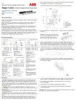
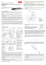
General description
Magne is an electromagnetic process lock that locks a door or hatch with a holding
force of up to 1500 N.
Magne 3 keeps a door locked to protect a process from unwanted interruptions. It
needs to be complemented by external interlocking devices if used in safety
applications.
Magne 4 has an integrated Eden sensor, which provides a high safety level of guard
interlocking protection. Magne 4 is available with built-in Adam DYN (DYNlink) or
Adam OSSD using an M12-5 or M12-8 connector.
Magne can be mounted on a door or a hatch with a JSM mounting kit, available for
either sliding doors or conventional doors (5–15 mm door gap). Y-connectors can be
used to connect several units. Magne 4 requires an Eva (which uses either a general or
unique code), an anchor plate “32B” (with built-in permanent magnet) or “32A”
(without permanent magnet) and a cellular rubber.
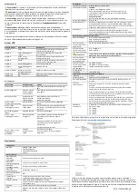
Electrical connections
M12 5-pole connector
M12 8-pole connector
1) Brown: Locking 24 VDC
1) White: DYNlink signal in
2) White: Not used
M12 5-pole connector
1) Brown: +24 VDC
2) White: DYNlink signal in
2) Brown: +24 VDC
3) Blue: 0 V
3) Blue: 0 V
3) Green: Locking 24 VDC
4) Black: Not used
4) Black: DYNlink signal out
4) Yellow: 0 V
5) Grey: Info output, locked
5) Grey: Locking 24 VDC
5) Grey: Info output (Eden &
locked)
6) Pink: DYNlink signal out
7) Blue: 0 V
8) Red: Not used
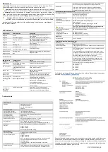
M12 8-pole connector
1) White: OSSD1 Out
2) Brown: +24 VDC
3) Green: OSSD1 in
4) Yellow: OSSD2 in
5) Grey: Info output (Eden &
Locked)
6) Pink: OSSD2 Output
7) Blue: 0 V
8) Red: Locking 24 VDC
Installation
Warning!
Magne shall be installed by a trained electrician following the Safety
regulations, standards and the Machinery directive. Installation shall be done in
accordance with a risk assessment for the individual application. Failure to comply
with instructions, operation that is not in accordance with the use prescribed in the
instructions, improper installation or handling of the device can affect the safety of
people and the plant.
Warning!
All safety functions shall be tested before starting up the system.
Warning!
Do not tamper or bypass the safety function. Failure can result in death
or serious injury.
Warning!
The M12 connector shall be connected after Magne has been installed
on the intended surface.
Caution!
Magne must be installed as close to the door handle as possible. The
distance between the lock and the handle creates a lever effect, reducing the holding
force.
Note!
Do not connect Magne to power supply before Eva is within sensing
distance. The Adam sensor within Magne 4 needs to learn the Eva code. Make sure
that no power supply is connected when the cable is fitted to the Magne PIN out.
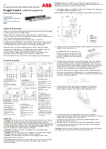
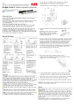
1.
Mount Magne and accessories,
as close to the door handle as possible. See the
Installation guide,
included in each JSM mounting kit.
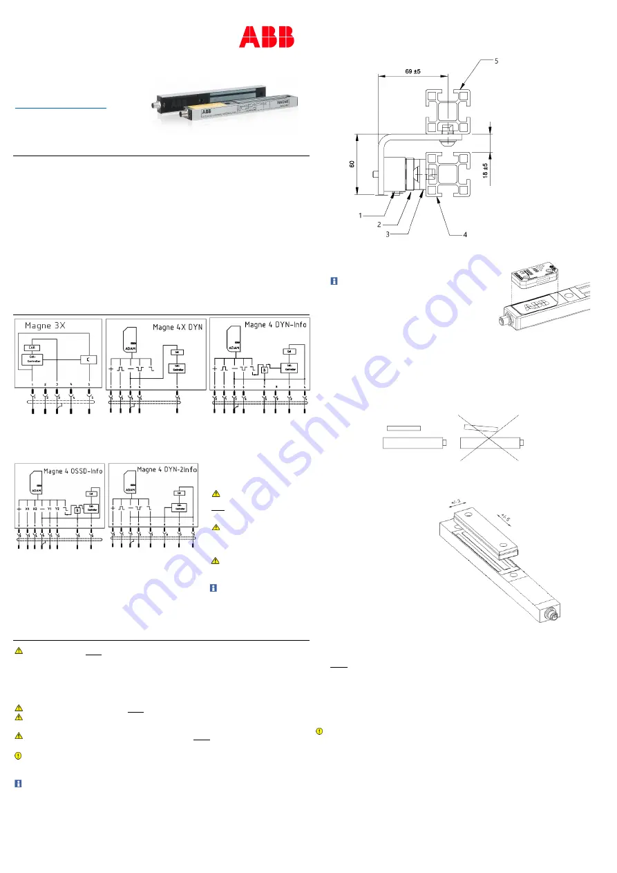
Installation tolerances (in mm) for Magne 3 and JSM D23 on a sliding door:
2.
Make sure that Eva is correctly positioned in relation to the built-in Adam sensor
in Magne 4.
Note!
It is very important that the units
are correctly positioned and that the safety
functions are tested. Magne 4’s safety
functionality is based on the Eden sensor.
3. Mount the anchor plate with 2 × M8 screws
with cellular rubber between the
anchor plate and the door. Do not compress the cellular rubber to a thickness less
than 8 mm. Recommended tightening torque is 7 ±2 Nm. Do not overtighten the
screws. This can deform the anchor plate, causing reduced or no holding force.
4. Check that the surfaces of the magnet and the anchor plate are completely
parallel, so that full contact is obtained when the door is closed. If the anchor
plate tilts, the holding force of the lock can be significantly reduced or eliminated
entirely.
5. Calibrate the position of the anchor plate with Magne. Maximum installation
tolerance between electromagnet and anchor plate is ±5 mm lengthways and ±3
mm sideways to Magne.
6. Connect the pin out according to section Electrical connections. Make sure that
no power supply is connected when the cable is fitted to the Magne PIN out.
7.
After Magne has been installed on the intended surface, connect the M12
connector to Magne.
8. Close the door to put Eva within sensing distance of Adam.
9. Connect Magne to the power supply. Green LED and blue LED should now
illuminate (solid light).
Caution!
After installation, check the looking function and check that the surfaces
of the magnet and the anchor plate are parallel.
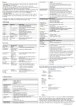
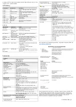
M12 8-pole connector
1) White: DYNlink signal in
2) Brown: +24 VDC
3) Green: Locking 24 VDC
4) Yellow: 0 V
5) Grey: Info output (Eden)
6) Pink: DYNlink signal out
7) Blue: 0V
8) Red: Info output (Locked)
Warning!
The info output is
non-failsafe and shall therefore
never
be used to control a safety
application.
Warning!
The safe signals
from the interlocking device Eden
are used to control the safety
application.
Warning!
Always use shielded
cables to connect the unit to the
rest of the safety circuit.
Note!
Several Magne 3X units
(using a M12-3A) or Magne OSSD-
Info units (using a M12-3G) can be
connected, but the info-signal will
not be available.
1.
Magne
2.
Anchor plate
3. Cellular rubber
4. Sliding door
5. Fence


