background image

LLT SIL FUNC TION A L S A FE T Y GU IDE

LLT100

Laser level transmitter

Summary of Contents for LLT100

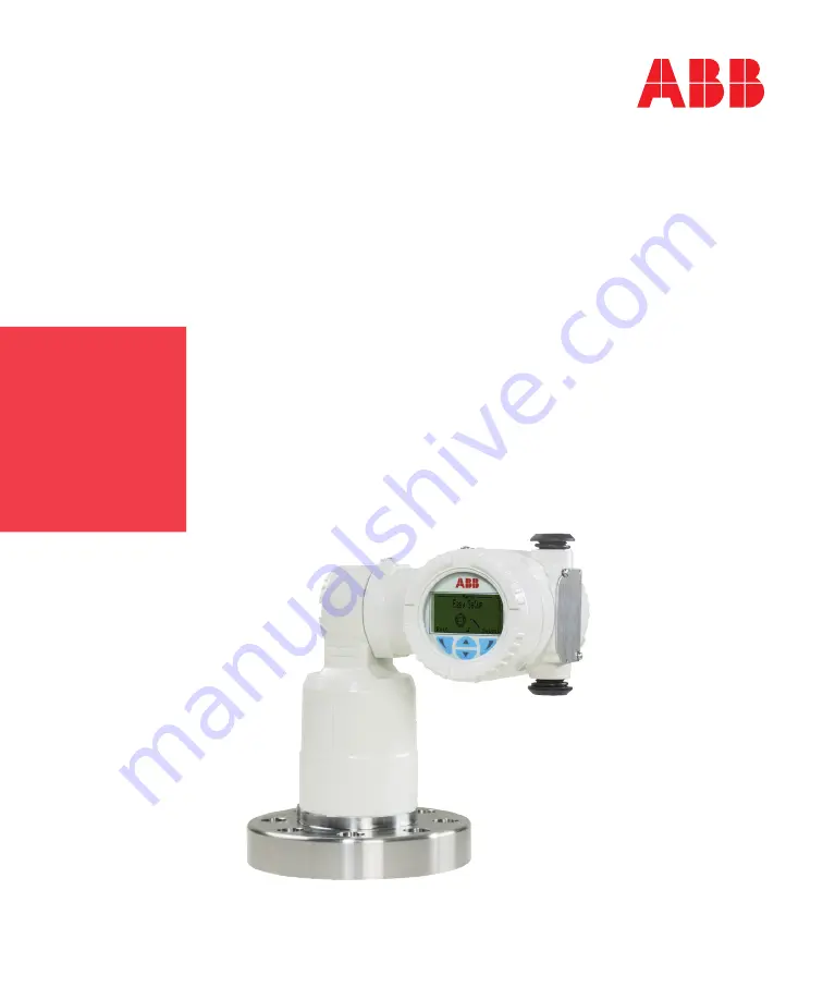
Page 1: ...LLT SIL FUNCTIONAL SAFET Y GUIDE LLT100 Laser level transmitter...

Page 2: ...in this document is current and accurate However no guarantee is given or implied that the document is error free or that the information is accurate ABB makes no representations or warranties with re...

Page 3: ...ilities 15 Systematic integrity 15 Random integrity 15 Safety parameters 15 General requirements 17 4 Installation and commissioning Installation 19 Physical location and placement 19 Electrical conne...

Page 4: ...Page intentionally left blank...

Page 5: ...ss of an automatic diagnostic and is not detected by another diagnostic Fail Dangerous Failure that does not respond to a demand from the process i e being unable to go to the defined fail safe state...

Page 6: ...r HFT Hardware Fault Tolerance Ability of a functional unit hardware to continue to perform a required function when faults or errors are prevailing HMI Human Machine Interface In this case the HMI is...

Page 7: ...ev D Operating Instruction http new abb com products measurement products level laser level transmitters llt100 AD2 DS_LLT100 EN_Rev C Datasheet http new abb com products measurement products level la...

Page 8: ...Page intentionally left blank...

Page 9: ...re and high temperature applications Ordering specifications are described in the LLT100 data sheet AD2 Refer to this data sheet to get exact measuring range operating temperature and accuracy specifi...

Page 10: ...to date revision in this table Safety Release Number Release Date Software Version FPGA Version Release Notes 1 15 June 2018 1 01 03 1 01 03 Initial safety version Restriction for combination of vesse...

Page 11: ...0 can be performed directly on its HMI or with HART communication protocol through a computer or handheld terminal The LLT100 connects to the user logic device to control one or multiple actuators for...

Page 12: ...2 of span 2 of 16 mA The safe state output current can be configured to be 3 6 mA low alarm or 21 0 mA high alarm with the exception of CPU faults where the current output is in low alarm mode 3 6 mA...

Page 13: ...en 10 s and 20 s due to internal power management constraints If a CPU fault occurs at startup during the instrument self test the current output is in low alarm mode 3 6 mA Power Failure Alarm Behavi...

Page 14: ...All other instrument configurations can be used for a Safety Instrumented Function Behavior for undetected faults If a LLT100 fault occurs and is not detected through its internal diagnostics the saf...

Page 15: ...ecific failure rates of all products included in the SIF Each subsystem must be checked to ensure compliance with minimum hardware fault tolerance requirements The safety parameters used for SIL calcu...

Page 16: ...3 All safety related parameters are calculated using the Exida Electrical and Mechanical Component Reliability Handbooks 4th edition The Exida environmental profile chosen for this FMEDA was Exida Pr...

Page 17: ...nfirming that the LLT100 nameplate contains the CS label as part of the model identification code An example of such a valid identification code is shown below LLT100 AIAH10L5 E03 CS P901 Personnel pe...

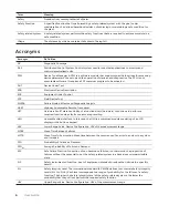
Page 18: ...18 User Guide...

Page 19: ...In solid applications if the laser is installed with an angle the setting level calibration points in AD1 shall be executed to calibrate the actual depth of the monitored vessel with the measured dept...

Page 20: ...ge or configuration of safety parameters the safety function of the device shall be verified see Verify safety function on page 21 After the safety function has been checked device operation must be l...

Page 21: ...A 1 From the Process Alarm menu select Process Alarm Limits Current Out Low Alarm or High Alarm 2 From there edit the value as necessary based on the information above 3 Press OK Verify safety functio...

Page 22: ...Page intentionally left blank...

Page 23: ...be performed by following the steps described below Testing the instrument To check the safety function of the device proceed as follows 1 Verify and record the conditions as they are found prior to c...

Page 24: ...12 Restart the device by powering it down 13 Check the measured distance or ullage against a secondary standard on an installed device which could be a calibrated reference device a mobile calibration...

Page 25: ...instrument is taken out of service Replacing modular components by original ABB spare parts is permitted if personnel was trained by ABB for this purpose Before sending the unit to ABB it must be clea...

Page 26: ...Page intentionally left blank...

Page 27: ...Chapter 6 Document status Change record Version Date Change Description A 18 June 2018 Initial release...

Page 28: ...Architecture Constraints must be verified for each application Safety Function The 4 to 20 mA current output will reflect the calibrated range in level volume or ullage as selected by the user within...

Page 29: ...C001 Certificate Certificat Zertifikat Series LLT100 Lidar Sensors Systematic Capability SC 2 SIL 2 Capable Random Capability Type B Element SIL 2 HFT 0 Route 1H PFH PFDavg and Architecture Constraint...

Page 30: ...Page intentionally left blank...

Page 31: ......

Page 32: ...dify the contents of this document without prior notice With regard to purchase orders the agreed particulars shall prevail ABB does not accept any responsibility whatsoever for potential errors or po...

Reviews: