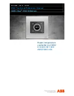
background image

1473-1-7819  

│  

Rev. 01  

│  

12.2012 

KNX Technical Reference Manual 

ABB-i-Bus

®

-KNX Millenium 


Room temperature 

controller incl. BAU


6124/20-981-500 

AMD70053-AN 


Summary of Contents for -i-Bus-KNX Millenium

Page 1: ...1473 1 7819 Rev 01 12 2012 KNX Technical Reference Manual ABB i Bus KNX Millenium Room temperature controller incl BAU 6124 20 981 500 AMD70053 AN...

Page 2: ...lectrical connection 16 7 Commissioning 17 7 1 Software 17 7 1 1 Preparatory steps 17 7 1 2 Assigning a physical address 17 7 1 3 Assigning the group address es 18 7 1 4 Selecting the application prog...

Page 3: ...l 1473 1 7819 3 11 3 2 Parameters for Control function Heating 30 11 3 3 Parameters for Control function Cooling 36 11 3 4 Parameters for Control function Heating and cooling 42 11 3 5 Parameters for...

Page 4: ...and adhered to Modifications and repairs to the product must only be undertaken if the manual expressly permits this It is only the adherence to the safety instructions and all safety and warning sym...

Page 5: ...signal word Caution indicates a possibly dangerous situation which could lead to slight or moderately serious injury Attention damage to property This symbol indicates a possibly harmful situation Non...

Page 6: ...ilator convector with a fan coil actuator or a conventional heating and cooling system Extensive functions are available for the room temperature controller The scope of the application is contained i...

Page 7: ...odification excludes the liability of the manufacturer for the damages caused It voids the warranty of the manufacturer 2 5 Environment Consider the protection of the environment Used electric and ele...

Page 8: ...This makes it possible to very quickly adjust the temperature in a hotel room to the individual wishes of the guests The device supports the full function for international hotel applications It can f...

Page 9: ...nical Reference Manual 1473 1 7819 9 3 2 Overview of devices 3 2 1 Front Position Function 1 Push buttons 2 Rotary control element 3 Display 3 2 2 Rear Position Function 1 KNX connection Note Observe...

Page 10: ...on KNX Technical Reference Manual 1473 1 7819 10 3 3 Cover frame and support ring Note A cover frame and a support ring from the Millenium program are additionally required see the following illustrat...

Page 11: ...ne 24 V DC Bus subscribers 1 12 mA KNX connection Bus connecting terminal screwless Protection type IP20 according to DIN EN 60529 Ambient temperature range 5 45 C Storage temperature range 20 70 C Di...

Page 12: ...rrect installation endangers your life and that of the user of the electrical system Incorrect installation can cause serious damage to property e g due to fire The minimum necessary expert knowledge...

Page 13: ...eight of approximately 150 cm from the floor and 50 cm from a door frame The room temperature controller should be installed on a wall opposite a radiator The angles of room architecture should not se...

Page 14: ...lectrical connection KNX Technical Reference Manual 1473 1 7819 14 Wetting the room temperature controller with fluids is to be avoided Just as heat radiated from electric loads can impair the tempera...

Page 15: ...g on page 10 1 The side of the support ring with the marking TOP must be aligned toward the top Now insert the device into the support ring in such a way that both sides with the marking TOP on the de...

Page 16: ...Manual 1473 1 7819 16 3 Then plug the cover frame onto the support ring Separate order see also chapter Cover frame and support ring on page 10 Fig 6 Attaching the cover frame 6 4 Electrical connecti...

Page 17: ...Software ETS from version ETS 3 0 f Use the appropriate commissioning tool Power Tool for the parameter settings 7 1 1 Preparatory steps 1 Connect a PC via the KNX interface e g the commissioning int...

Page 18: ...the application program Please contact our Internet support unit www Busch Jaeger com The application is loaded into the device via the ETS 7 1 5 Differentiating the application program Various funct...

Page 19: ...on for activating deactivating the room temperature controller Note The basic setting of the display always indicates the set point temperature or the fan speed level Starting from paragraph General c...

Page 20: ...ntilation Ventilation deactivated or on standby Fan speed level during manual ventilation Room temperature controller On or Off Eco mode 8 3 LED colour concept 8 3 1 Explanation Colour Meaning White S...

Page 21: ...functions of the buttons in connection with the rotary control element and the display are described in the following The precise function is fixed via the assigned application function and their par...

Page 22: ...perature is shown in the display Whenever the set point temperature is unequal to the actual temperature the indication changes from white to orange or blue Here the background is appropriately colour...

Page 23: ...esired fan speed level or the desired operating status is displayed 3 Press the button Fan speed levels or wait until the set time expires The adjustment is stored Fig 13 Device in fan speed level set...

Page 24: ...the ECO mode absence state 2 After a renewed press of the ECO mode button the device returns to the settings that were active prior to the activation of ECO mode Fig 14 Device in ECO mode Note During...

Page 25: ...th slightly moistened with a soap solution can be used Caustic cleaning agents or solvents must not be used 10 Maintenance The unit is maintenance free In case of damage e g during transport or storag...

Page 26: ...mperature controller contains the applications listed in the following KNX application Page Temperature reading 27 RTC settings 29 Operating mode settings 61 Depending on which device and application...

Page 27: ...s not even Parameters General parameter Settings Comments Internal temperature measurement activated deactivated Cycle time for sending of the actual temperature mm ss 00 25 90 00 Additional parameter...

Page 28: ...e Manual ABB i Bus KNX Millenium Description of applications objects KNX Technical Reference Manual 1473 1 7819 28 Objects No Object name Data type Flags 0 Output 2 Byte EIS5 DPT 9 001 C T 1 Alarm 1 B...

Page 29: ...l parameter Settings Comments Operating as RTC extension unit activated deactivated Parameters for Temperature reading Settings Comments Operating mode for fault Heating Cooling Only available when pa...

Page 30: ...ttings Comments Additional heating stage deactivated activated Parameters for Setting operating modes Settings Comments Operating mode after reset Standby Comfort ECO mode Frost heat protection Genera...

Page 31: ...ea for manual set value setting is set on 1 K 15 K Resetting of the manual adjustment for receipt of a basic set value deactivated activated Resetting of the manuel adjustment for change of operation...

Page 32: ...heating Normal inverse Hysteresis heating 1 10 K 3 255 Only available when parameter Control type heating is set on 2 point 1 bit Off On or 2 point 1 byte 0 100 cyclical sending of the control value...

Page 33: ...et on PI continuous or on FanCoil Additional parameters for Control function Heating Settings Comments Control value difference PI continuous for sending of the control value heating deactivated 2 5 1...

Page 34: ...ted Position output only manuel manual and auto Format of the stage output 0 5 0 255 1 bit m of n 1 bit 1 of n Control value output for fan stage 1 heating 0 255 0 255 Control value output for fan sta...

Page 35: ...set on activated Additional parameters for Control function Heating Settings Comments Output additional stage heating 2 point 1 bit Off On 2 point 1 byte 0 100 Mode of the control value of the additi...

Page 36: ...ents Operating mode after reset Standby Comfort ECO mode Frost heat protection Parameters for Alarm function Settings Comments Condensate water alarm deactivated activated Dew point alarm deactivated...

Page 37: ...r manual set value setting is set on 1 K 15 K Resetting of the manual adjustment for receipt of a basic set value deactivated activated Resetting of the manuel adjustment for change of operation mode...

Page 38: ...Mode of the control value for cooling Normal inverse Hysteresis cooling 1 10 K 3 255 Only available when parameter Control type cooling is set on 2 point 1 bit Off On or 2 point 1 byte 0 100 cyclical...

Page 39: ...et on PI continuous or on FanCoil Additional parameters for Control function Cooling Settings Comments Control value difference PI continuous for sending of the control value cooling deactivated 2 5 1...

Page 40: ...eps 5 steps Evaluation stage status deactivated activated Control value output for fan stage 1 cooling 0 255 0 255 Control value output for fan stage 2 cooling 0 255 0 255 Control value output for fan...

Page 41: ...set on activated Additional parameters for Control function Cooling Settings Comments Output additional stage cooling 2 point 1 bit Off On 2 point 1 byte 0 100 Mode of the control value of the additi...

Page 42: ...ects Output control value additional stage heating and cooling via 1 object via 2 objects Additional heating stage deactivated activated Additional cooling stage deactivated activated Parameters for S...

Page 43: ...r Set values manual Settings Comments Area for manual set value setting deactivated 1 K 2 K 3 K 4 K 5 K 6 K 7 K 8 K 9 K 10 K 11 K 12 K 13 K 14 K 15 K max manual lowering during cooling mode 0 15 K 0 1...

Page 44: ...ndby heating setting dependent K 0 15 Setpoint temperature ECO heating setting dependent K 0 15 Setpoint frost C 5 40 Parameters for Dead zone Settings Comments Distance heating cooling comfort K 1 10...

Page 45: ...Mode of the control value for heating Normal inverse Hysteresis heating 1 10 K 3 255 Only available when parameter Control type heating is set on 2 point 1 bit Off On or 2 point 1 byte 0 100 cyclical...

Page 46: ...l value heating 0 255 Additional parameters for Control function Cooling Settings Comments Control parameter via system type Free paramaterization P amount cooling 1 10 K 10 100 Only available when pa...

Page 47: ...te The following parameters are available only when parameter Control type heating or Control type cooling is set on PI continuous or PI PWM 1 bit Additional parameters for Control function Heating Se...

Page 48: ...stages 3 steps 5 steps Evaluation stage status deactivated activated Control value output for fan stage 1 heating 0 255 0 255 Control value output for fan stage 2 heating 0 255 0 255 Control value ou...

Page 49: ...vated Control value output for fan stage 1 cooling 0 255 0 255 Control value output for fan stage 2 cooling 0 255 0 255 Control value output for fan stage 3 cooling 0 255 0 255 Control value output fo...

Page 50: ...e additional stage heating Normal inverse Temperature difference additional stage heating x 0 1K 0 255 upper hysteresis of the additional stage heating x 0 1K 0 255 cyclical sending of the control val...

Page 51: ...ects Output control value additional stage heating and cooling via 1 object via 2 objects Additional heating stage deactivated activated Additional cooling stage deactivated activated Parameters for S...

Page 52: ...r Set values manual Settings Comments Area for manual set value setting deactivated 1 K 2 K 3 K 4 K 5 K 6 K 7 K 8 K 9 K 10 K 11 K 12 K 13 K 14 K 15 K max manual lowering during cooling mode 0 15 K 0 1...

Page 53: ...K 0 15 Setpoint temperature ECO heating setting dependent K 0 15 Setpoint frost C 5 40 Parameters for Dead zone Settings Comments Distance heating cooling comfort K 1 10 min dead zone heating cooling...

Page 54: ...Mode of the control value for heating Normal inverse Hysteresis heating 1 10 K 3 255 Only available when parameter Control type heating is set on 2 point 1 bit Off On or 2 point 1 byte 0 100 cyclical...

Page 55: ...ntrol parameter via system type Free paramaterization P amount cooling 1 10 K 10 100 Only available when parameter Control parameter is set on Free paramaterization I component cooling min 0 255 max c...

Page 56: ...te The following parameters are available only when parameter Control type heating or Control type cooling is set on PI continuous or PI PWM 1 bit Additional parameters for Control function Heating Se...

Page 57: ...vated activated Position output only manuel manual and auto Format of the stage output 0 5 0 255 1 bit m of n 1 bit 1 of n Control value output for fan stage 1 heating 0 255 0 255 Control value output...

Page 58: ...vated Control value output for fan stage 1 cooling 0 255 0 255 Control value output for fan stage 2 cooling 0 255 0 255 Control value output for fan stage 3 cooling 0 255 0 255 Control value output fo...

Page 59: ...e additional stage heating Normal inverse Temperature difference additional stage heating x 0 1K 0 255 upper hysteresis of the additional stage heating x 0 1K 0 255 cyclical sending of the control val...

Page 60: ...U 19 Reset onsite operation 1 Bit EIS1 DPT 1 001 C W U 20 Heating and cooling control value 1 Byte EIS6 DPT 5 001 C W T U 21 Cooling control value 1 Byte EIS6 DPT 5 001 C W T U 22 Cooling control val...

Page 61: ...mp back time into primary function 5 s 10 s 20 s 30 s 1 min 2 min 4 min Temperature adjustment in ECO mode deactivated activated Display of actual temperature deactivated activated Parameters for Temp...

Page 62: ...ake technical changes as well as changes to the contents of this document without prior notice The detailed specifications agreed to at the time of ordering apply to all orders ABB accepts no responsi...

Reviews: