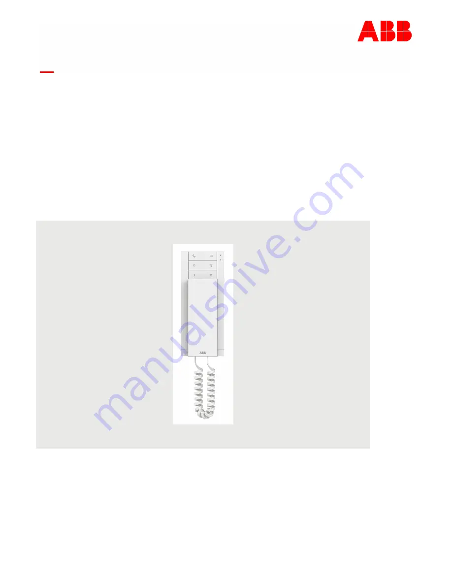
background image

2TMD042200D0001

  31.08.2022

Product manual

ABB-Welcome IP

H82001-W Audio IP

Summary of Contents for H82001-W

Page 1: ...2TMD042200D0001 31 08 2022 Product manual ABB Welcome IP H82001 W Audio IP ...

Page 2: ... 2 Adding Audio IP via App 17 8 1 3 Importing a building structure via App 19 8 1 4 Accessing the setting screen 22 8 1 5 Basic information 23 8 1 6 Call button setting 24 8 1 7 Unlock button setting 26 8 1 8 Light button setting 28 8 1 9 Programmed button setting 29 8 1 10 Guard unit setting 33 8 1 11 Physical address IP address setting 34 8 1 12 Logical address setting 38 8 1 13 Ringtone setting...

Page 3: ...0001 3 9 1 2 Intercom 55 9 1 3 Unlock 56 9 1 4 Turn on a light 57 9 1 5 SOS 58 10 Cyber security 59 10 1 Disclaimer 59 10 2 Performance and service 60 10 3 Deployment guideline 60 10 4 Upgrading 61 10 5 Malware prevention solution 61 11 Notice 62 ...

Page 4: ...ith it ABB accepts no liability for any failure to observe the instructions in this manual 2 Safety Warning Electric voltage Dangerous currents flow through the body when coming into direct or indirect contact with live components This can result in electric shock burns or even death Disconnect the mains power supply prior to installation and or disassembly Permit work on the 100 240 V supply syst...

Page 5: ...y 4 1 ABB devices All packaging materials and devices from ABB bear the markings and test seals for proper disposal Always dispose of the packing materials and electric devices and their components via an authorized collection facility or disposal company ABB products meet the legal requirements in particular the laws governing electronic and electrical devices and the REACH ordinance EU Directive...

Page 6: ...ription Product manual 2TMD042200D0001 6 5 Product description 5 1 Device type Article number Order number Product name Colour Size DxHxW Unit mm H82001 W 2TMA130011W0001 Audio IP induction loop White 81 x 198 x 43 ...

Page 7: ... for the functions below Intercom to same unit default Intercom to another unit Call guard unit Open door with Outdoor station Open door with IP actuator Turn on the designated light SOS function 4 Light button In standby status press the button to turn on the designated light In standby status hold the button for 5 seconds to set the ringtone type During communication hold the button for 5 second...

Page 8: ...e Automatic unlock function and the LED red will turn off The Automatic unlock function means the door will be unlocked automatically during a call request This function will be disabled automatically after 10 hours 7 LED red 8 LED blue 9 Mute button In standby status press the button to mute the ringtone In standby status hold the button for 3 seconds to mute the ringtone for all the indoor stati...

Page 9: ...owly Red LED flashes fast Blue LED flashes fast LED status LED status Description Auto unlock function is enabled Mute the speaker or the microphone Unsigned status or enters the setting mode During an incoming call Operation failed Operation success IP address conflicts or network connection is not working properly Two LEDs flash alternative update the firmware ...

Page 10: ...anual 2TMD042200D0001 10 5 3 Terminal description No Description 1 A potential free contact such as a doorbell 2 Micro SD card slot only for factory use 3 LAN PoE PoE is the only power supply for this device 4 Reset button 1 2 3 4 ...

Page 11: ...001 11 6 Technical data Designation Value Rating voltage 48 V Operating voltage 38 57 V Rating current 48 V 40 mA Operating temperature 10 C 55 C Storage temperature 25 C 70 C PoE standard IEEE802 3 af IP level IP 30 Size DxHxW 81 x 198 x 43 mm ...

Page 12: ...edge and experience Incorrect installation endangers your life and that of the user of the electrical system Incorrect installation can cause serious damage to property e g due to fire The minimum necessary expert knowledge and requirements for the installation are as follows Apply the five safety rules DIN VDE 0105 EN 50110 1 Disconnect 2 Secure against being re connected 3 Ensure there is no vol...

Page 13: ...Mounting Installation Product manual 2TMD042200D0001 13 7 2 Product dimensions Unit mm 7 3 Installation height 198 81 20 9 43 1 5 m 5 feet ...

Page 14: ...lation 1 Disassemble the upper part from the bottom part by using a screwdriver 2 A Affix the bottom part on the wall 2 B Affix the bottom part on the box 3 Connect the wires 4 Latch the upper part onto the bottom part 174 60 60 83 3 79 2 Global VDE BS CN NEMA Italy Swiss 1 2 A 2 B 3 4 maximum length 100 mm Optional ...

Page 15: ...rsion should be 5 92 or later Audio IP should not be signed by other Smart Access Point If Audio IP has been signed by other Smart Access Point you need to clear the signature e g reset the Audio IP by pressing and holding the reset button for 3 seconds on the back Please follow the steps below 1 On the configuration screen of Smart Access Point click Door entry system to access the corresponding ...

Page 16: ...number 5 Enter floor number 6 Enter room number 7 Enter device ID Master indoor station device ID is 1 Slave indoor station If Audio IP is connected to the common network device ID can be 2 3 If Audio IP is connected to the home network device ID can be 2 32 8 Enter the serial number pasted on the back of the device 9 Click Save ...

Page 17: ...reset the Audio IP by pressing and holding the reset button for 3 seconds on the back Select Setup Welcome IP when login into App A project has been created on the App this project includes the designated buildings floors and rooms Please follow the steps below 1 Open the App go to a designated room screen click 2 Scan the QR code on the back of Audio IP and then continue from step 4 3 Or click Se...

Page 18: ...the home network device ID can be 2 32 5 Enter the location information 6 Set the device type to Indoor station 7 Click Add 8 On the designated room screen the result is displayed on the screen PoEswitch Smart Access Point Outdoor station Master IS Master IS Standalone Home router Slave 1 Slave 2 Slave1 Slave2 Apartment1 Apartment2 Apartment3 Max32 indoor stations inthesameapartment Max3 indoor st...

Page 19: ...le buildings as a batch Importing rule Building structure will be overwritten according to the building number App buildings Smart Access Point original buildings Smart Access Point final buildings B A B C A B C B C A B C A B C D E F A B C A B C D E F means the building structure has been changed Precondition App must be on the same network with the router connected to Smart Access Point SmartAP R...

Page 20: ...Commissioning Product manual 2TMD042200D0001 20 Please follow the steps below 1 On the Main menu screen of Smart Access Point click 2 A pop up window will be displayed on the screen Now turn to the App ...

Page 21: ...nated project screen swipe the project to the right 4 Click 5 Click the designated Smart Access Point 6 Enter the admin name and password which is used to login Smart Access Point 7 Click OK 8 Click OK 9 On the Main menu screen of Smart Access Point click to finish the importing ...

Page 22: ...0D0001 22 8 1 4 Accessing the setting screen Please follow the steps below 1 On the Main menu screen of Smart Access Point Click Door entry system 2 Click Indoor stations 3 Go to Audio Indoor Station section 4 Click the designated Audio IP ...

Page 23: ...n On the designated Audio IP screen No Description 1 View the physical address 2 View the logical address 3 View the IP address 4 View the first name and the last name of the resident or the tenant 5 View the serial number 6 View the firmware version 7 View the signature ...

Page 24: ...low 1 On the designated Audio IP screen go to the Button settings section 2 Click Call options The call button can be set to 3 types of functions Intercom to same unit Please follow the steps below 1 On the Call options screen select Intercom to same unit 2 Select the target it can be Group call or designated call 3 Click Save ...

Page 25: ...ions screen select Intercom to other unit 2 Set the position for the designated indoor station e g building floor and apartment 3 Click Save Call guard unit Please follow the steps below 1 On the Call options screen select Call guard unit 2 Click Save Note Guard unit address needs to be set before calling a guard unit ...

Page 26: ... Button settings section 2 Click Door lock settings The unlock button can be set to 2 types of functions Open door with Outdoor station Please follow the steps below 1 On the Door lock settings screen select Open door with Outdoor station 2 Select the designated outdoor station or gate station 3 Select the lock type it can be set to Default lock or Subsidiary lock 4 Click Save ...

Page 27: ... with IP actuator Please follow the steps below 1 On the Door lock settings screen select Open door with IP actuator 2 Select the designated IP actuator connected by the lock 3 Select the lock type it can be set to Default lock or Subsidiary lock 4 Click Save ...

Page 28: ...042200D0001 28 8 1 8 Light button setting Please follow the steps below 1 On the designated Audio IP screen go to the Button settings section 2 Click Light switch 3 Select the designated IP actuator connected by the light 4 Click Save ...

Page 29: ...below 1 On the designated Audio IP screen go to the Button settings section 2 Click Button 1 2 The programmed button can be set to 7 types of functions Intercom to same unit Please follow the steps below 1 On the Button 1 2 screen select Intercom to same unit 2 Select the target it can be Group call or designated call 3 Click Save ...

Page 30: ... 1 2 screen select Intercom to other unit 2 Set the position for the designated indoor station e g building floor and apartment 3 Click Save Call guard unit Please follow the steps below 1 On the Button 1 2 screen select Call guard unit 2 Click Save Note Guard unit address needs to be set before calling a guard unit ...

Page 31: ...esignated outdoor station or gate station 3 Select the lock type it can be set to Default lock or Subsidiary lock 4 Click Save Open door with IP actuator Please follow the steps below 1 On the Button 1 2 screen select Open door with IP actuator 2 Select the designated IP actuator connected to by the lock 3 Select the lock type it can be set to Default lock or Subsidiary lock 4 Click Save ...

Page 32: ...e steps below 1 On the Button 1 2 screen select Light switch 2 Select the designated IP actuator connected by the light 3 Click Save SOS call Guard unit address needs to be set before SOS call Please follow the steps below 1 On the Button 1 2 screen select SOS call 2 Click Save ...

Page 33: ... manual 2TMD042200D0001 33 8 1 10 Guard unit setting Please follow the steps below 1 On the designated Audio IP screen go to Guard unit settings section 2 Click Guard unit settings 3 Set the default Guard unit 4 Click Save ...

Page 34: ...ndoor station Master mode Subsidiary mode only one indoor station can be set to master mode in the same apartment other indoor stations must be set to the subsidiary mode Independent mode if an indoor station is set to independent mode no other devices can be supported PoE switch SmartAccess Point Outdoor station Master IS Master IS Stand alone Home router Slave 1 Slave 2 Slave1 Slave 2 Apartment1...

Page 35: ...o Additional settings section 2 Click Physical address IP address Master mode Only the Audio IPs connect to common network can be set to Master mode Please follow the steps below 1 On the Physical address IP address screen select Master mode 2 Enter the physical address 3 IP address is generated automatically and cannot be modified 4 Click Save ...

Page 36: ...cal address IP address screen select Subsidiary mode 2 Enter the physical address 3 IP address setting If Audio IP connects to common network then IP address is generated automatically and cannot be modified If Audio IP connects to home network then IP address can be set to DHCP or Static address 4 Click Save ...

Page 37: ...he Audio IPs connect to common network can be set to Independent mode Please follow the steps below 1 On the Physical address IP address screen select Independent mode 2 Enter the physical address 3 IP address is generated automatically and cannot be modified 4 Click Save ...

Page 38: ...t manual 2TMD042200D0001 38 8 1 12 Logical address setting Please follow the steps below 1 On the designated Audio IP screen go to Additional settings section 2 Click Logic address 3 Enter the logical address 4 Click Save ...

Page 39: ...ings section 2 Click Ringtone 3 Select the designated ringtones for different types of devices 5 types of ringtones can be selected 4 Repeated tone function Tick the check box to enable the function the ringtone will ring repeatedly within 30 seconds during an incoming call Untick the check box to disable the function the ringtone will ring only once 5 Click Save ...

Page 40: ...l 2TMD042200D0001 40 8 1 14 Renaming the device Please follow the steps below 1 On the designated Audio IP screen go to Additional settings section 2 Click Resident s Tenant s 3 Enter the last name and the first name 4 Click Save ...

Page 41: ...Commissioning Product manual 2TMD042200D0001 41 5 The name is displayed on the screen ...

Page 42: ...ate Please follow the steps below 1 On the designated Audio IP screen go to Additional settings section 2 Click Local firmware update 3 Click Browser to add the firmware update file 4 Click Browser to add the firmware signature file 5 Click Save to upload the updating files ...

Page 43: ...Commissioning Product manual 2TMD042200D0001 43 6 Click after uploading the update files successfully 7 Click Save 8 Click to accept the End User License Agreement ...

Page 44: ...1 44 9 A pop up window appears to indicate the updating details e g Device ID updating progress The pop up window can be hidden by clicking Minimize The updating will be stop if Cancel the update is clicked 10 Click Close to complete the update ...

Page 45: ...e designated Audio IP screen go to Additional settings section 2 Click Online firmware update Smart Access Point must be connected to the Internet 3 Current firmware version is displayed on the screen 4 New firmware version is detected automatically from the website 5 Click Save to update the firmware automatically ...

Page 46: ...roduct manual 2TMD042200D0001 46 8 1 17 Multiple devices setting Please follow the steps below 1 On the Indoor stations screen go to Audio Indoor Station section 2 Click 3 Select the designated Audio IPs 4 Click Next ...

Page 47: ...Commissioning Product manual 2TMD042200D0001 47 5 Select the designated function and carry on the same setting for multiple devices 6 Click Save ...

Page 48: ...Commissioning Product manual 2TMD042200D0001 48 8 2 Setting on local device 8 2 1 Ring volume setting Adjust the three level selector maximum medium low to set the ringtone volume ...

Page 49: ... button for 5 seconds to enter the setting mode Red LED and blue LED flash slowly at the same time 2 Press the lock button to play the current ringtone 3 Press the lock button repeatedly until the designated ringtone sounds 5 types of ringtones can be selected 4 Press and hold the light button for 5 seconds to exit the setting mode Red LED and blue LED turn off at the same time ...

Page 50: ...econds to enter the setting mode Red LED and blue LED flash slowly at the same time 2 Press the mute button to play the current ringtone 3 Press the mute button repeatedly until the designated ringtone sounds 5 types of ringtones can be selected 4 Press and hold the light button for 5 seconds to exit the setting mode Red LED and blue LED turn off at the same time ...

Page 51: ...ng During communication press and hold the light button for 5 seconds to access the setting mode and then select the designated volume by pressing this button repeatedly 5 levels of volume can be selected Press and hold the light button for 5 seconds again to exit the setting ...

Page 52: ...tion will be disabled automatically after 10 hours In standby status press and hold the lock button for 10 seconds to enable the Automatic unlock function Red LED illuminates to indicate that the Automatic unlock function is enabled The same operation will disable the Automatic unlock function and Red LED will turn off Note Slave Audio IP does not support Automatic unlock function ...

Page 53: ...e steps below 1 Disassemble the upper part from the bottom part by using a screwdriver 2 Pressing and holding the reset button on the upper part 3 seconds to reset the device Note Building address signature and all parameters will be restored to factory settings after the reset operation 1 2 ...

Page 54: ... 54 9 Operation 9 1 1 Incoming call During a call request pick up the handset within 30 seconds to accept the call During communication hang up the handset to terminate the call During a call request press the mute button to mute the ringtone ...

Page 55: ...ing on page 24 Operation In standby status pick up the handset and press the call button to initiate an intercom 2 Intercom via programmed button Precondition Programmed button should be set before use Please see chapter 8 1 9 Programmed button setting on page 29 Operation In standby status pick up the handset and press the designated programmed button to initiate an intercom ...

Page 56: ...Unlock button setting on page 26 Operation In standby status press the unlock button to release the designated lock 2 Unlock via programmed button Precondition Programmed button should be set before use Please see chapter 8 1 9 Programmed button setting on page 29 Operation In standby status press the designated programmed button to release the designated lock ...

Page 57: ... button setting on page 28 Operation In standby status press the light button to turn on the designated light 2 Turn on light via programmed button Precondition Programmed button should be set to Turn on light before use Please see chapter 8 1 9 Programmed button setting on page 29 Operation In standby status press the designated programmed button to turn on the designated light ...

Page 58: ...n Programmed button should be set to SOS call before use Please see chapter 8 1 9 Programmed button setting on page 29 Operation In standby status press and hold the designated programmed button at least 2 seconds to send an alarm to Guard unit or Smart Access Point ...

Page 59: ...e H82001 W product the network its system and interfaces against any kind of security breaches unauthorized access interference intrusion leakage and or theft of data or information ABB Ltd and its affiliates are not liable for damages and or losses related to such security breaches unauthorized access interference intrusion leakage and or theft of data or information Although ABB provides functio...

Page 60: ... for connectivity detection 7006 TCP To be used for connectivity detection 10777 TLS Secure channel for device management 10 3 Deployment guideline Please do not install it within a public place and ensure that physical access to the devices is granted only to trusted personal All devices on one system shall be signed by a public CA at the commissioning stage in normal situations the management so...

Page 61: ... their devices using firmware that has not been officially released by ABB 10 5 Malware prevention solution All official firmware versions of the device are scanned for malware before release and the firmware upgrade mechanism ensures that only the legally released firmware can be upgraded While ABB provides maximum security for its products it strongly advises users not to disassemble the devices...

Page 62: ...ed specifications agreed to at the time of ordering apply to all orders ABB accepts no responsibility for possible errors or incompleteness in this document We reserve all rights to this document and the topics and illustrations contained therein The document and its contents or excerpts thereof must not be reproduced transmitted or reused by third parties without prior written consent by ABB ...

Page 63: ...nt We reserve all rights to this document and the topics and illustrations contained therein The document and its contents or extracts thereof must not be reproduced transmitted or reused by third parties without prior written consent by ABB ABB Xiamen Smart Technology Co Ltd No 881 FangShanXiEr Road Xiang An Industrial Area Torch Hi Tech Industrial Development Zone Xiamen Tel 86 592 295 9000 Fax ...

Reviews: