background image

Options for ABB drives, converters and inverters

User’s manual

FDIO-01 digital I/O extension module

Summary of Contents for FDIO-01

Page 1: ...Options for ABB drives converters and inverters User s manual FDIO 01 digital I O extension module ...

Page 2: ...hardware manual 3AXD50000022021 ACS880 17 drives hardware manual 3AXD50000020436 ACS880 37 drives hardware manual 3AXD50000020437 ACS880 107 inverter units hardware manual 3AUA0000102519 ACS880 207 IGBT supply units hardware manual 3AUA0000130644 ACS880 307 A003 diode supply units hardware manual 3AUA0000102453 ACS880 307 A018 diode supply units hardware manual 3AXD50000011408 ACS880 607 1 phase b...

Page 3: ...FDIO 01 digital I O extension module 3AUA0000124966 Rev B EN EFFECTIVE 2015 11 30 2015 ABB Oy All Rights Reserved 1 Safety instructions Table of contents 4 Mechanical installation 5 Electrical installation 6 Start up ...

Page 4: ......

Page 5: ... Product overview 13 Layout 14 Hardware filtering for DC input signals 15 4 Mechanical installation Contents of this chapter 17 Necessary tools and instructions 17 Unpacking and examining the delivery 17 Installing the module 18 onto the drive control unit 18 onto an extension adapter module 19 5 Electrical installation Contents of this chapter 21 Warnings 21 Necessary tools and instructions 21 Ad...

Page 6: ...Ds 27 8 Technical data Contents of this chapter 29 Dimension drawing 30 Data 31 Installation 31 Degree of protection 31 Ambient conditions 31 Package 31 Hardware settings 31 Isolation areas 32 Digital inputs XDI1 1 2 XDI2 3 4 XDI3 5 6 32 Relay outputs XRO1 11 13 XRO2 21 23 33 Power supply 33 General 33 Further information Product and service inquiries 35 Product training 35 Providing feedback on A...

Page 7: ...the warning symbols used in this manual and the safety instructions which you must obey when you install or connect an optional module to a drive converter or inverter If you ignore the safety instructions injury death or damage can occur Read this chapter before you start the installation ...

Page 8: ...also tell you how to prevent the danger The manual uses these warning symbols Electricity warning tells you about hazards from electricity which can cause injury or death or damage to the equipment General warning tells you about conditions other than those caused by electricity which can cause injury or death or damage to the equipment ...

Page 9: ...sconnect the drive converter or inverter from all possible power sources After you have disconnected the drive converter or inverter always wait for 5 minutes to let the intermediate circuit capacitors discharge before you continue Disconnect all dangerous voltages connected to other control signal connectors in reach For example it is possible that 230 V AC is connected from outside to a relay ou...

Page 10: ...10 Safety instructions ...

Page 11: ...se and service the extension module Before you do work on the module read this manual and the applicable drive converter inverter manual that contains the hardware and safety instructions for the product in question You are expected to know the fundamentals of electricity wiring electrical components and electrical schematic symbols The manual is written for readers worldwide Both SI and imperial ...

Page 12: ...e Electrical installation contains instructions on adjusting hardware filtering for DC input signals and wiring the extension module Start up contains instructions on starting up the extension module Diagnostics shows how to trace faults with the status LED on the extension module Technical data contains the technical data of the extension module Terms and abbreviations Later in this manual term d...

Page 13: ...s and two relay outputs Compared to the FIO 01 digital I O extension module FDIO 01 has a wider input voltage range and basic insulation between all inputs outputs and the drive control unit interface If you connect one or more inputs outputs to the AC power line you can still safely connect the other inputs outputs and the drive control unit inputs outputs to SELV or PELV circuits The extension m...

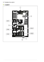
Page 14: ...14 Hardware description Layout 3 5 1 1 XRO1 XRO2 XDI1 XDI2 XDI3 4 2 ...

Page 15: ...e filtering time of the digital input in question to 1 ms Shortening the filtering time to 1 ms will however reduce the noise immunity of the input Note You must always use a 10 millisecond filtering time with an AC input signal Item Description Additional information 1 Retaining clips Page 18 2 Lock 3 Mounting screw 4 DIP switches for hardware filtering Page 15 22 XDI1 2 pin detachable terminal b...

Page 16: ...16 Hardware description ...

Page 17: ...and instructions on installing the extension module Necessary tools and instructions See the applicable drive hardware manual Unpacking and examining the delivery 1 Open the option package 2 Make sure that the package contains FDIO 01 digital I O extension module this manual 3 Make sure that there are no signs of damage ...

Page 18: ...o its position on the drive until the retaining clips lock it into position 3 Push in the lock 4 Tighten the screw to 0 8 N m Note The screw tightens the connections and grounds the module It is necessary for fulfilling the EMC requirements and for proper operation of the module WARNING Do not tighten the screw tighter than 0 8 N m Too big torque value breaks the thread See the applicable drive ma...

Page 19: ... installation 19 onto an extension adapter module For instructions on how to install the module onto an extension adapter module see FEA 03 F series extension adapter user s manual 3AUA0000115811 English 4 2 3 1 ...

Page 20: ...20 Mechanical installation ...

Page 21: ... for DC input signals and wiring the extension module Warnings WARNING Obey the safety instructions See chapter Safety instructions on page 7 If you ignore the safety instructions injury or death can occur If you are not a qualified electrician do not do electrical work Necessary tools and instructions See the applicable drive hardware manual ...

Page 22: ...signals Set the DIP switches see page 14 to the applicable positions for the necessary inputs This table shows the possible positions for each input Filtering time DIP switch setting XDI1 XDI2 XDI3 10 ms default 1 ms 1ms 10ms 1ms 10ms 1ms 10ms 1ms 10ms 1ms 10ms 1ms 10ms ...

Page 23: ...g Description XDI1 1 1 Digital input 1 terminal 1 2 2 Digital input 1 terminal 2 XDI2 3 3 Digital input 2 terminal 3 4 4 Digital input 2 terminal 4 XDI3 5 5 Digital input 3 terminal 5 6 6 Digital input 3 terminal 6 Marking Description XRO1 11 NC Relay output 1 normally closed 12 COM Relay output 1 common 13 NO Relay output 1 normally open XRO2 21 NC Relay output 2 normally closed 22 COM Relay outp...

Page 24: ... Electrical installation Wiring Connect the external control cables to the applicable module terminals Digital input wiring example XDIx 1 2 XDIx 1 2 110 230 V AC 10 24 250 V DC polarity unimportant FDIO ...

Page 25: ...t Make sure that you have completed these start up tasks for the drive Checks and settings with no voltage connected Powering up the drive Setting up the drive control program See the applicable drive hardware manual Setting the parameters The extension module is started up through drive parameters See the applicable firmware manual ...

Page 26: ...26 Start up ...

Page 27: ...ts and warning messages For the fault and warning messages concerning the extension module see the drive firmware manual LEDs The extension module has one diagnostic LED Color Description Green The extension module is powered up Red There is no communication with the drive control unit or the extension module has detected some other error ...

Page 28: ...28 Diagnostics ...

Page 29: ...Technical data 29 Technical data Contents of this chapter This chapter contains the technical data of the extension module ...

Page 30: ...30 Technical data Dimension drawing The dimensions are in millimeters ...

Page 31: ...nsion adapter module FEA 03 Degree of protection IP20 Ambient conditions The applicable ambient conditions specified for the drive in its manuals are in effect Package Cardboard Plastic wrapping Antistatic air bubble sheet PE Hardware settings One DIP switch per digital input for hardware filtering ...

Page 32: ...AC Logic levels DC 0 5 V 1 15 V Logic levels AC 110 230 V 10 0 5 Vrms 1 20 Vrms Input currents 10 mA at 24 V DC 3 mA at 230 V AC Filtering times selectable for all channels 10 ms default 1 ms Inputs isolated from each other the relay outputs power supply and ground earth Varistor protected 250 V Insulation strength 4 kV Symbol Description Basic insulation IEC 61800 5 1 2007 ...

Page 33: ...mum current 10 mA 24 V DC Contact material AgNi Outputs isolated from each other the digital inputs power supply and ground earth Contact protection Varistor 250 V Insulation strength 4 kV Power supply 3 3 V and 24 V supplied by the drive control unit or the FEA 03 extension adapter module Max power consumption 100 mA at 3 3 V 25 mA at 24 V General Complies with standards EN 61800 3 EN 61800 5 1 U...

Page 34: ...34 Technical data ...

Page 35: ...ntacts can be found by navigating to www abb com searchchannels Product training For information on ABB product training navigate to new abb com service training Providing feedback on ABB Drives manuals Your comments on our manuals are welcome Navigate to new abb com drives manuals feedback form Document library on the Internet You can find manuals and other product documents in PDF format on the ...

Page 36: ...Contact us www abb com drives www abb com solar www abb com windconverters www abb com drivespartners 3AUA0000124966 Rev B EN 2015 11 30 ...

Reviews: