Programming guide COI/AZ30E–EN Rev. D
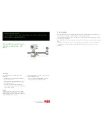
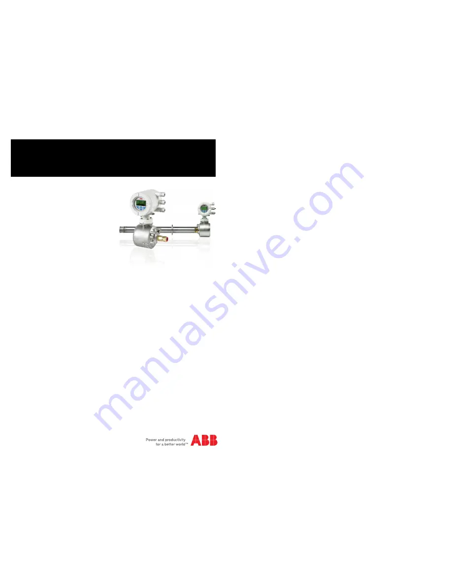
Endura AZ30 series integral probe and remote transmitter
Combustion oxygen monitor
Proven technology for use in
hazardous area gases and
dusts
Introduction
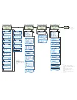
This Programming Guide provides the following
information:
–
installation details for a remote AZ30 transmitter –
see section 4, page 11
–
probe cable, power supply and output connection
details for remote and integral AZ30 transmitters –
see section 5, page 18
–
programming, calibration and troubleshooting
information for remote and integral AZ30 transmitters
– see Section 6, page 30
Warning
The AZ30 combustion oxygen monitor is a certified
product suitable for use in hazardous area locations.
Before using this product refer to the product labeling for
details of hazardous area certification.
This Programming Guide should be used in conjunction
with the following publications:
–
Probe User Guide OI/AZ30P–EN (remote probe)
–
Probe Maintenance Guide (MI/AZ30M–EN)
The Company
We are an established world force in the design and manufacture of instrumentation for industrial process
control, flow measurement, gas and liquid analysis and environmental applications.
As a part of ABB, a world leader in process automation technology, we offer customers application expertise,
service and support worldwide.
We are committed to teamwork, high quality manufacturing, advanced technology and unrivalled service and
support.
The quality, accuracy and performance of the Company’s products result from over 100 years experience,
combined with a continuous program of innovative design and development to incorporate the latest
technology.


