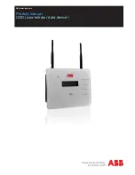
background image

ABB solar inverters

Product manual

CDD (concentrator data device)

Summary of Contents for CDD

Page 1: ...ABB solar inverters Product manual CDD concentrator data device ...

Page 2: ...d the user authority to operate the equipment FCC REMARKS The equipment has been tested and found to comply with the limits for a Class B digital device pursuant to Part 15 of the FCC Rules These limits are designed to provide reasonable protection against harmful interference in a residential installation This equipment generates uses and can radiate radio frequency energy and if not installed an...

Page 3: ...e 1 Introduction and safety 2 Plan the installation 3 CDD display operations 4 Connect and configure the CDD 5 Acquire the MICRO inverters 6 System monitoring 7 Appendix CDD Product manual BCG 00613 1_AA NA Rev 1 0 Copyright 2014 ABB All Rights Reserved ...

Page 4: ...e networks without a MAC address filter 17 Secure networks with a MAC address filter 17 Autoconnection configuration 17 DHCP configuration 18 IP address view 18 Ethernet connection to the internet 19 Firmware upgrade 20 CDD display operations 21 LED and display operations 21 Description of the display menus 22 General Information cyclical display 24 Basic information menu 24 Main menu Statistics 2...

Page 5: ...D web server 36 HOME page 36 VIEW menu 37 CONFIG menu 38 EVENTS menu 40 UPGRADE menu 40 REGISTRATION menu 42 HELP menu 42 Appendix 43 The MICRO inverter system 43 Characteristics of MICRO inverters 43 Description of the CDD 44 Alarm messages and codes 44 Making a service call 49 Routine maintenance 49 Technical data and types 49 Wireless routers compatible with CDD 50 ...

Page 6: ... 6 002TC ...

Page 7: ...L60950 1 Safety of Information Technology Equipment General Requirements Part 1 CSA 60950 1 07 Safety of Information Technology Equipment General Requirements Part 1 Intended use This equipment is a device designed to configure and control a network of ABB MICRO inverters using radio communication and to supply data relating to the system using a wireless connection or an Ethernet port to an inter...

Page 8: ...n MAC address Ethernet MAC address When registering the CDD on the Easy View portal the MAC RF radio frequency address is used as the product identification code see System monitoring Part 6 Regulatory nameplate The nameplate shown is affixed to the inverter and provides the following information Technical data reported in this manual does not replace the data on the labels affixed to the equipmen...

Page 9: ...g in the display menu Operating status and statistics of each MICRO inverter Operating status of the connection to the internet local network Alarm messages and fault indicators The menus are navigated by means of buttons on the side of the CDD 01 Wireless antenna 02 Status LED not on all models 03 Radio antenna MICRO inverter 04 Display 05 Button pad 06 Ethernet port 07 Power connector 08 Etherne...

Page 10: ...parameters Setting of grid standard for the country region of installation These operations can be carried out using the CDD display or the Web Server integrated in the CDD When configuring using the Web Server it is necessary to connect the CDD to a PC via Ethernet or Wireless see configuration and connection details in part 4 Once the configuration has been completed the device can be registered...

Page 11: ...s available on the compatibility list found in the appendix part 7 and available online at www abb com solarinverters For Ethernet communication there must be an unused Ethernet port on the router For installations with multiple CDDs it is recommended to acquire all MICRO inverters before mounting them on the roof using the MICRO preinstallation kit and related guidelines Choose a place close to a...

Page 12: ...in the CDD display see part 3 An extension cable for the antenna can also be installed The cable allows the antenna to be installed at a distance from the CDD to go over or around possible obstacles to the radio signal The extended antenna can be installed in an outdoor rated plastic box see technical note online Improving CDD Wireless Signal Reception for detailed instructions 15cm 6in above a ro...

Page 13: ...ooden Wooden Concrete Windows Wooden Distance less than 7 5m 25ft Distance less than 10m 33ft Distance less than 30m 100ft Metal or reinforced concrete Metal or reinforced concrete Distance more than 7 5m 25ft Evaluate the RF signal quality and the possibility to extend the RF antenna externally Evaluate the RF signal quality and the possibility to extend the RF antenna externally or to install th...

Page 14: ... part 5 it can be determined if reception from the inverters and router is sufficient or if the final position or location of the CDD should be changed Make the two holes necessary using a drill with a 5 mm diameter bit The depth of the holes must be around 30 mm Insert plugs in the holes and tighten the countersunk screws supplied Fasten the CDD by putting the head of the screws in the two holes ...

Page 15: ...em to access the CDD internal configuration pages local web server and for data transmission to the web portal in order to monitor the system The wireless connection of the CDD to the computer requires the use of a wireless router acting as a bridge for the transmission of data The configuration of the wireless network is done on the CDD display using the panel buttons described below Turn on the ...

Page 16: ...ted network Open WPA WPA2 If no wireless networks are found it may be necessary to change the DHCP settings page 24 Open networks with a MAC address filter The MAC address is used to set up the configuration menu of the router which is not supplied by ABB Refer to documentation from the manufacturer of the router for instructions to add the CDD to the list of enabled MAC addresses on the router Th...

Page 17: ...tered correctly it will be necessary to configure the MAC address filter with the same procedure set out on the previous page for Open networks with a MAC address filter Open Autoconnection configuration The CDD automatically memorizes the parameters of the last wireless connection made SSID and network key TheAutoconnect feature enables the CDD to automatically connect tothelastwirelessnetworksel...

Page 18: ... ENTER Scroll DOWN to the Network submenu Press ENTER and scroll to DHCP Enabled Press ENTER and choose to Enable or Disable the DHCP function YES NO Press ENTER to confirm Step 3 Re Enable the wireless following Step 1 above Press ENTER to remove the arrow next to NO Use the UP or DOWN button to choose the option YES Press ENTER to confirm If the DHCP function is Disabled it is necessary to set u...

Page 19: ...st character input When the password has been entered scroll to the CHANGE SETTINGS menu and press ENTER Scroll to Network and press ENTER to select Scroll to select Select Network WLess and press ENTER Scroll to Ethernet and press ENTER to select The CDD will automatically restart to reset the connection settings Connect the Ethernet cable if not already connected Two possibilities for cabled con...

Page 20: ...y address is 192 168 0 100 type 192 168 0 101 and click OK The IP Gateway address of the CDD is shown on the display by pressing any button and scrolling DOWN the basic list Once these parameters are changed input the IP Gateway address of the CDD in the address bar of the Internet Browser to proceed with the acquisition of the plant To reset the wireless connection on the computer follow the step...

Page 21: ...GREEN No errors or alarms generated Installation of CDD and MICRO inverters is operational STEADY GREEN Reporting of radio communication problems between MICRO inverters and CDD or between CDD and Router A transitional or permanent state caused by the failure to receive data by the CDD or by an absent or bad connection between the CDD and the router FLASHING RED Minor warnings Warning message code...

Page 22: ...en the main menus for statistics data display and default settings An outline of the menu structure is shown below A detailed description of the menu items can be found in the table on page 14 Total Energy KWh Tot output power W System quality MICRO X EXTRA Y Alarm status DD MM YY HH MM SS Network Web Server IP MAC Addr WLess Subnet Mask St View Info Chan Sett IP Gateway Primary DNS Secondary DNS ...

Page 23: ...sk Tot output Power W Statistics Total Energy kWh Inverter data PN View Information SN Firmware rel Date DD MM YY Time HH MM SS Events Alarm Present Change Language Change Settins Set Date Time Set Time Zone Display Timeout Network Reset Ground Fault ateway ary DNS dary DNS Enabled Yes AutoConn Yes Server Password s SSID on during normal access to set up e BASIC menu of the CDD The three MAIN menu...

Page 24: ...ss connectivity is enabled by default Press ENTER to remove arrow press DOWN to scroll to NO press ENTER to select NO and disable wireless connectivity Wless AutoConn Yes auto connection to last network connected is recommended and enabled by default press ENTER to remove arrow press DOWN to scroll to NO press ENTER to select NO and disable Web Server Reset Password default password admin of the l...

Page 25: ...nd locked To change to Ethernet wireless must first be disabled from BASIC menu Network once wireless is disabled press ENTER to change to Ethernet Reset Ground Fault Reset Are you sure press ENTER to reset Geo Position of the plant press ENTER to change use UP DOWN to enter latitude and longitude press ENTER to accept change Lat Long N S xx xx E W xx xx Country STD grid country standard of the in...

Page 26: ... 26 010CC4 4 CDD display operations ...

Page 27: ... the menus Use the UP and DOWN buttons to navigate to the CHANGE SETTINGS menu Press ENTER and scroll to DOWN to Micro Manager The MicroManager ADD Inverter screen opens Press ENTER and the Lat Long screen opens Use the UP and DOWN keys to enter the latitude and longitude of the system Press ENTER to confirm and the Set Timezone screen opens Use the UP and DOWN keys to select the applicable time z...

Page 28: ...ress ENTER to confirm completion OK Country Standard screen opens and displays the first grid country standard in the list Press ENTER to remove the arrow and scroll DOWN the list of available country grid standards Press ENTER to select the applicable standard to be passed to the acquired inverters When complete the CDD returns to the MicroManager Add Inverters screen Press ESC to exit the MAIN m...

Page 29: ... drop down CONFIG menu on the Home page Authentication is required Enter the default access credentials Username admin Password admin Press OK Click to view a drop down list of timezones Use the drop down list to view grid country standards Click confirm to make changes ...

Page 30: ...e is no timeout for the acquisition procedure Click on STOP ACQUISITION to manually terminate the procdure once all the inverters are displayed Inverters are identified by MAC address MACRF and or serial number SN Use check box to select inverters for acquisition Press CONFIRM to complete ...

Page 31: ...stration procedure is described in part 6 System monitoring If the the registation has been bypassed until later the Home page will be displayed Click on HOME in the menu to exit Micro Manager Upon successful completion of the configuration procedures the CDD can be mounted to the wall as described in section 2 Select this link to register the CDD on the web portal Click here to complete the acqui...

Page 32: ... 32 011CC5 5 Acquire the MICRO inverters ...

Page 33: ...ration procedure described below Self registration procedure To start the self registration process go to https register auroravision net cdd mac AA BB CC DD EE FF GG II The page will automatically open at the end of the acquisistion process for the MICRO inverter when CLICK HERE TO REGISTER YOUR CDD XX XX XX XX XX XX XX XX is selected 6 System monitoring Read through the overview to understand th...

Page 34: ...and contact information to help direct current and future homeowners to the installer for any future project and service needs Siteinformationdefaultstothehomeowner address but can updated to a different address for alternate locations such as a second home Step 3 Link and validate the CDD to the solar power site Make sure the CDD is connected to the internet Enter the CDD s RF MAC address MAC RF ...

Page 35: ...raph of total production of energy for a period which can be set from a single day up to 365 and the output power of each MICRO inverter On the bottom are the Environmental Benefits based on the total energy produced by the plant In addition to monitoring the portal offers automatic upgrade of the firmware installed in the MICRO inverters and the CDD When new firmware is available an e mail is sen...

Page 36: ...me of the display Fw RF Radio frequency firmware version INV STAT allows 3 states RUN booster generating power START UP inverter awakening and PROT inverter into protection uP inverter firmware version VOUT Output voltage IDs IOUT Output current DSP DSP firmware version FREQ Frequency IDi VIN Input voltage PN part number POUT Output power MODEL DESC inverter model EN TOT Total energy produced SIGN...

Page 37: ...are refreshed every 15 minutes Each MICRO Inverter sends a package of data to the CDD once a minute In order to accurately evaluate a CDD positioning wait 15 minutes from the power on of the device Average signal strength Messages received by the CDD from each inverter in the last 15 minutes RSSI received signal strength indicator a measurement of the power present in a received radio signal from ...

Page 38: ...e zone and country standard Config Network provides basic information of the connected network Config Date Time used to adjust date and time Config CDD clone allows configuration of a new CDD with the same settings as a previous CDD by using the last 4 pairs of digits of the old CDD s MAC address Click to view a drop down list of timezones Use the drop down list to view grid country standards Clic...

Page 39: ...country standard Config Ground Fault Energy options to reset ground fault and or reset energy history for statistical views Config Change Pass use to change the default password admin Enter default password enter and retype new password and click Confirm to change ...

Page 40: ...cludes errors Exxx and alarms Wxxx codes see Appendix Part 5 for a complete description of these events UPGRADE menu The Upgrade menu can be used to upgrade firmware of the CDD and MICRO inverter and load an updated country standard list CDD Remote Upgr Updates must be enabled on the Config Network menu to be available for upgrade ...

Page 41: ...d select Upload Step 2 Load wireless firmware Select click here link to reboot CDD and apply update confirm firmware revision from View Info menu or the CDD display Step 3 final Reboot CDD CDD Local Upgr The CDD firmware is available on the web site https registration ABBsolarinverters com or by contacting customer service Download the files and save them on a computer to perform a local updgrade ...

Page 42: ...ountry standards The firmware must first be downloaded and saved on a computer in order to browse and select the files for upload see CDD Local upgrade above REGISTRATION menu This menu will launch the Aurora Vision welcome page See Remote monitoring Self Registation on page 33 for instructions to complete the process HELP menu Identified by a question mark on the menu bar the help menu contains t...

Page 43: ...y system then powers all connected electrical devices from lighting to household appliances etc When the photovoltaic system is not supplying sufficient power the power needed to ensure normal operation of the connected electrical devices is drawn from the utility grid If on the other hand excess power is produced this is fed directly into the grid becoming available to other consumers In accordan...

Page 44: ...he error appears when the inverter input current exceeds the set overcurrent threshold This may be caused by a sudden sunlight changes that may generate input current surges into the MICRO inverter b PV module incompatible with the MICRO inverter input charac teristics c Faulty MICRO inverter a The error occurs sporadically and no action is required as the MICRO in verter will automatically reset ...

Page 45: ...erTemp High internal temperature record ed by the inverter This parameter depends in part on the power that the inverter must supply as the internal inverter temperature is affected by the heat dissipated internally by its components This may be caused by a Failure to observe the installa tion conditions b Internal inverter fault a Verify the installation conditions exposure to sunlight and check ...

Page 46: ...on s applicable regula tion In any case the inverter will automatically try to reconnect to the grid This may be caused by a Sporadic recurrence of this error is a sign of large grid dis tortions or sudden changes in irradiance b Systematic recurrence of this error may be due to an inverter fault a Verify the grid parameters and if the grid voltage is strongly distorted please contact your grid op...

Page 47: ...re better radio signal quality b System configuration must be carried out in good irradiance condi tions in order to guarantee the correct operation of the MICRO inverter and to prevent the risk of shut downs due to insufficient input voltage generated by the PV module E501 Blinking green Communica tion fault The alarm is generated when the CDD device does not receive messages from the MICRO in ve...

Page 48: ...oltage for instabilities in any of the 4 parameters monitored by the inverter If anomalous values are de tected verify the sizing of the AC line conductors In case of correct sizing please contact your grid operator to address the problem W011 Solid red Vbulk UV Internal fault of the booster circuit inverter Contact customer service W032 Blinking green Pgrid limita tion MICRO is limiting AC power ...

Page 49: ...unication Radio IEEE 802 11 b 2 4GHz 10Mbps Wired communication Ethernet RJ45 10 100Mbps Connectivity Wired ports 1x RJ45 Ethernet Features Operation Integrated web server Power supply Type External plug in adapter Adaptor input 100 to 240Vac 50 60Hz Adaptor output 5Vdc 1A Power consumption typ 2 5W max 5W Environmental IP degree IP20 NEMA 1 Ambient temperature 4 F to 131 F 20 C to 55 C Relative h...

Page 50: ... 1 18 1 05 Buffalo WHR HP G54 1 40 1 0 37 1 08 1 04 Buffalo WHR HP GN DD WRT v24SP2 EU US 08 19 10 std Cisco E1000 2 0 00 build 14 May 13 2010 Cisco E3000 1 0 03 build 2 Sep 7 2010 Cisco E4200 1 0 02 build 13 May 24 2011 Cisco M20 v1 0 01 build 7 Apr 15 2010 Cisco Vallet M10 v1 0 00 build 018 Jan 26 2010 Corega CG WLBARGO 1 05 D Link DI 524 3 23 Wed 28 Jun 2006 D Link DIR615 5 00NA D Link DIR 615 ...

Page 51: ...R854T 1 4 34NA PCI MZK W04NU 1 00 03 Wed Nov 28 21 03 53 JST 2007 SMC SMCWBR14S N4 V0 0 4 4 Dec 8 2009 SMC SMCWBR14T G V2 02 May 16 2005 5 09 36 TP Link TL WR340G 4 7 11 Build 101102 Rel 60376n TP Link TL WR541G TL WR542G 4 0 1 Build 08 1021 Rel 48660n TP Link TL WR740N 3 12 4 Build 100910 Rel 57694n TP Link TL WR741ND 3 12 4 Build 100910 Rel 57694n TP Link TL WR841ND 3 12 5 Build 100929 Rel 57776...

Page 52: ...Further information For more information onABB products and services for solar applications navigate to www abb com solarinverters ...

Page 53: ...Contact us www abb com solarinverters CDD Product Manual BCG 00613 1_AA NA REV 1 0 Copyright 2014 ABB All Rights Reserved ...

Reviews: