background image

ABB drives

Supplement

ACX580-01 R1-R3 Flange mounting kit installation

Summary of Contents for ACX580-01 R1

Page 1: ...ABB drives Supplement ACX580 01 R1 R3 Flange mounting kit installation ...
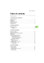
Page 2: ...s and guides Code English Flange mounting kit quick installation guide for ACX580 01 frames R1 to R3 3AXD50000119172 ACS580 01 0 75 to 250 kW hardware manual 3AXD50000018826 ACS580 01 quick installation and start up guide for frames R1 to R5 3AXD50000044838 ACH580 01 0 75 to 250 kW hardware manual 3AUA0000076331 ACH580 01 quick installation and start up guide 3AUA0000076330 ACQ580 01 0 75 to 250 k...

Page 3: ...Supplement Flange mounting kit installation 3AXD50000119189 Rev A EN EFFECTIVE 2017 10 10 2017 ABB Oy All Rights Reserved Table of contents 3 Mechanical installation ...

Page 4: ......

Page 5: ...site 14 Additional requirements for cabinet installations 14 Necessary tools 14 Moving the drive 14 Unpacking and examining the delivery 15 Transport package contents 15 ACX580 01 frames R1 to R3 15 Flange mounting kit package contents 16 ACX580 01 frames R1 to R3 16 Example mounting template 17 Installing the drive 18 Free space requirements 18 Installing drives above one another 19 Installation ...

Page 6: ...mensions 35 ACX580 01 frame R3 36 Flange mounting kit 36 Attaching points and hole dimensions 38 Further information Product and service inquiries 39 Product training 39 Providing feedback on ABB Drives manuals 39 Document library on the Internet 39 ...

Page 7: ...ructions in this supplement Target audience This supplement is intended for people who plan the installation and install the drive with the flange mounting kit Read the supplement before you work on the drive You are expected to know the fundamentals of electricity wiring electrical components and electrical schematic symbols The supplement is written for readers worldwide Both SI and imperial uni...

Page 8: ...lement introduces the supplement Hardware description describes the flange mounting kit Mechanical installation describes how to install the drive with the flange mounting kit mechanically Dimension drawings contains dimension drawings of the flange mounting kit Related documents See List of related manuals on the inside of the front cover ...

Page 9: ... mounting kit is a plus code option C135 or can be ordered with these ordering codes also separately For R1 and R2 the degree of protection of a flange mounted IP21 drive unit is IP20 on the front side and IP55 on the backside For R3 the degree of protection of a flange mounted IP55 IP21 drive is IP55 IP21 on the front side and IP55 on the backside Special requirements For R1 and R2 cable boxes ar...

Page 10: ...u must leave the drive cover in place See the tables for more information Frame size ACX580 01 IP21 ACX580 01 IP55 R1 Delivered with cover Insert sealing plug Exception In dry environment you can leave the cover in place without inserting a sealing plug R2 R3 Delivered with cover Insert sealing plug You can leave the cover in place ...

Page 11: ...p flange bracket 3 Lifting hole 4 Side flange bracket 5 Cable shelf 6 Bottom flange bracket 7 Grouding plate 8 Drive heat sink in the cooling air channel 1 3 4 2 4 3 5 Note If flanges are mounted cable boxes are removed from R1 and R2 drive modules 6 7 8 ...

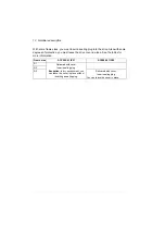
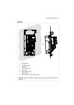
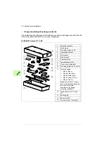
Page 12: ...12 Hardware description ...

Page 13: ...Mechanical installation 13 3 Mechanical installation Contents of this chapter This chapter describes how to install the drive with the flange mounting kit mechanically ...

Page 14: ...e material below the installation is not flammable There is enough free space above and below the drive for cooling air flow service and maintenance There is enough free space in front of the drive for operation service and maintenance See section Free space requirements on page 18 and Dimensions weights and free space requirements in the hardware manual Additional requirements for cabinet install...

Page 15: ...gns of damage Read the data on the type designation label of the drive to make sure that the drive is of the correct type ACX580 01 frames R1 to R3 The flange mounting kit package is tied onto the drive package To unpack Cut the straps Remove the flange mounting kit package For the contents of the kit package see Flange mounting kit package contents on page 16 Open the drive cardboard box For the ...

Page 16: ...ightening brackets 5 Top bracket 6 Side brackets 7 Cardboard tray 8 Top cardboard cover 9 Option kit package label 10 Grounding plate for R1 or R2 11 Screw package M4 nut 4pcs M4 8 screw 2pcs M5 20 screw 4pcs M6 25 screw 14pcs M6 nut 19pcs Note The amount of screws and nuts delivered in package are more than actual requirement for flange mounting installation 12 Hood required for UL type 12 13 Sea...

Page 17: ... size for drilling the attaching holes and cutting the holes in the mounting plate For drilling the holes see the installation procedures for ACX580 01 frames R1 to R3 Note The delivery does not include the Rivet or Kalei nuts for the M6 screws Consider the hole size for the nuts An example template is shown below ...

Page 18: ... space requirements The flange mounted drives can be installed side by side For free space requirements above and below the drives see the table ACX580 01 Above Below mm in mm in R1 200 7 87 200 7 87 R2 200 7 87 200 7 87 R3 200 7 87 200 7 87 Above Below ...

Page 19: ...hanical installation 19 Installing drives above one another Make sure that the outlet cooling air flows away from the drive above 200 mm 7 87 in 120 mm 4 72 in 120 mm 4 72 in 300 mm 11 81 in 250 mm 9 84 in ...

Page 20: ...tion procedure ACX580 01 frames R1 to R3 1 Frames R1 and R2 To remove the cable box front cover is removed firstly Reinstall the cover and screws 2 Frames R1 to R3 To remove the fan assembly push the retaining clips Lift the assembly up ...

Page 21: ...Mechanical installation 21 3 Frames R3 Insert the sealing plug to the hole shown in the figure Note For IP55 UL Type 12 unit only 4 Frames R1 to R3 Reinstall the fan assembly ...

Page 22: ...st attach the side brackets a to the top and bottom U brackets with M6 nuts Then attach the tightening brackets b to the both ends with M5 20 screws 4 M6 nut 6 N m 4 M5 20 screw 3 N m R1 R3 4 M6 nut 6 N m a a b b Note Attach this end of the side brackets to the bottom U bracket to make sure that the sealing is tight ...

Page 23: ...Attach the top c and bottom d brackets to the side brackets first the inner sides of the top and bottom brackets the sides that touch the drive then the outer sides Remove the tightening bracket e from the front of the fan 8 M6 nut 6 N m c d c d e ...

Page 24: ... install the power cable shelf lower on the bottom bracket first remove the cover and lead through plate Then detach the power cable shelf and attach it to the bottom bracket with M4 nuts Frame R3 2 M4 nut 1 5 N m Note Use the uninstalled screw from drive for grouding Frames R1 R2 2 M4 nut 1 5 N m 2 M4 8 Combi screw 1 5 N m ...

Page 25: ...al installation 25 Note Frame R3 is shown here as an example The cable shelf varies in different frame sizes 2 M4 nut 1 5 N m Note Reinstall the screws to avoid moisture exchange through the empty holes 1 5 N m ...

Page 26: ...the flange mounting kit package onto the mounting plate Note Mounting templates are different size number and position of holes for different frame sizes Note The delivery does not include Rivet or Kalei nuts for the M6 mounting screws Make the opening and drill the holes for the mounting screws Consider the hole size for the Rivet or Kalei nuts Remove the mounting template ...

Page 27: ... drives Attach the hood to the cooling channel Note UL Type 12 is fulfilled on the drive backside when the flange and hood are installed Step 10 is not required for IP55 Bottom Top Back Back Front R1 R2 2 M6 nuts R3 3 M6 nuts 6 N m Front Back ...

Page 28: ...ng device onto the opening in the mounting plate 12 Attach the bottom bracket with one screw 13 Attach the top bracket with one screw 14 Attach the rest of the mounting screws Remove the chains 11 12 13 14 1 M6 25 screw 6 N m 1 M6 25 screw 6 N m R1 8 M6 25 screw R2 10 M6 25 screw R3 12 M6 25 screw 6 N m ...

Page 29: ...Dimension drawings 29 4 Dimension drawings Contents of this chapter This chapter contains the dimension drawings of the flange mounting kits and required openings in the mounting plate ...

Page 30: ...30 Dimension drawings ACX580 01 frame R1 Flange mounting kit 3AXD50000131310 ...

Page 31: ...Dimension drawings 31 Hood is needed for UL Type 12 drives 3AXD50000131242 ...

Page 32: ...32 Dimension drawings Attaching points and hole dimensions 3AXD50000038098 ...

Page 33: ...Dimension drawings 33 ACX580 01 frame R2 Flange mounting kit 3AXD50000131327 ...

Page 34: ...34 Dimension drawings Hood is needed for UL Type 12 drives 3AXD50000130863 ...

Page 35: ...Dimension drawings 35 Attaching points and hole dimensions 3AXD50000038111 ...

Page 36: ...36 Dimension drawings ACX580 01 frame R3 Flange mounting kit 3AXD50000131143 ...

Page 37: ...Dimension drawings 37 Hood is needed for UL Type 12 drives 3AXD50000130870 ...

Page 38: ...38 Dimension drawings Attaching points and hole dimensions 3AXD50000038117 ...

Page 39: ...ntacts can be found by navigating to www abb com searchchannels Product training For information on ABB product training navigate to new abb com service training Providing feedback on ABB Drives manuals Your comments on our manuals are welcome Navigate to new abb com drives manuals feedback form Document library on the Internet You can find manuals and other product documents in PDF format on the ...

Page 40: ...Contact us www abb com drives www abb com drivespartners 3AXD50000119189 RevA EN 2017 10 10 ...

Reviews: