background image

ABB INDUSTRIAL DRIVES

ACS880-604 3-phase brake units as modules

Hardware manual

Summary of Contents for ACS880-604

Page 1: ... ABB INDUSTRIAL DRIVES ACS880 604 3 phase brake units as modules Hardware manual ...

Page 2: ......

Page 3: ... 604 3 phase brake units as modules Hardware manual Table of contents 4 Cabinet construction 6 Electrical installation 9 Start up 2019 ABB Oy All Rights Reserved 3AXD50000022033 Rev D EN EFFECTIVE 2019 09 30 ...

Page 4: ......

Page 5: ...nectors X50 X53 19 Fibre optic connectors 20 Overview circuit diagram of the brake unit 21 Frame R8i layout 22 Overview of power and control connections 23 Brake unit control devices 23 Overview of the control connections of the BCU control unit 24 The control panel 24 Control by PC tools 24 Fieldbus control 24 DC switch and charging switch 25 Inverter module type designation label 26 Type designa...

Page 6: ...rake resistors 46 Selecting and routing the brake resistor cables 46 Typical resistor cable sizes 46 Minimizing electromagnetic interference 46 Maximum cable length 46 EMC compliance of the complete installation 46 Placing the brake resistors 47 Selecting the resistor thermal switch circuit cable 47 Protecting the system against thermal overload 47 Operation principle 47 Protecting the system agai...

Page 7: ...procedure 10 Fault tracing 71 Contents of this chapter 71 Fault indications 72 LEDs 72 Control panel and panel platform holder LEDs 72 Control unit LEDs 73 R8i module LEDs 73 Warning and fault messages 73 7 segment display of the brake control unit 11 Maintenance 75 Contents of this chapter 75 Maintenance intervals 75 Maintenance instructions 12 Ordering information 77 Contents of this chapter 77 ...

Page 8: ...ble sizes 103 Typical resistor cable sizes 103 Maximum cable length 104 Fuses 104 Allowable mounting orientations 104 Dimensions and weights 105 Free space requirements 105 Losses cooling data and noise 106 Input power DC connection 106 Resistor connection 106 Efficiency 106 Degree of protection 106 Ambient conditions 108 Materials 108 Standards 108 Markings 109 Auxiliary circuit current consumpti...

Page 9: ...G01 122 Charging controller 123 Miscellaneous components 123 Quick connector for frame R8i 125 Insertion extraction ramp for frame R8i modules 127 CRBB 4 400 188 cooling fan 15 Example circuit diagrams 129 Contents of this chapter 129 Component designations used in the diagrams 130 Frame 1 R8i with DC switch disconnector Sheet 001 Main circuit 130 Frame 1 R8i with DC switch disconnector Sheet 020 ...

Page 10: ...10 ...

Page 11: ...tware function specific warnings and notes before changing the default settings of a function For each function the warnings and notes are given in the section describing the related user adjustable parameters Read the task specific safety instructions before starting the task See the section describing the task Target audience This manual is intended for people who plan the installation install s...

Page 12: ...primary control program quick start up guide Brake module and DC DC converter module manuals 3AUA0000106244 ACS880 604 1 phase brake chopper modules hardware manual 3AXD50000022033 ACS880 604 3 phase brake modules hardware manual 3AXD50000020967 ACS880 3 phase brake control program firmware manual 3AXD50000023642 ACS880 1604 DC DC converter modules hardware manual 3AXD50000024671 ACS880 DC DC conv...

Page 13: ...trolled cooling fan BFPS Conducts the surplus energy from the intermediate circuit of the drive to the brake resistor when necessary The chopper operates when the DC link voltage exceeds a certain maximum limit The voltage rise is typically caused by deceleration braking of a high inertia motor Brake chopper Brake chopper enclosed in a metal frame or housing Intended for cabinet installa tion Brak...

Page 14: ...same ma chinery Includes one supply unit and one or several inverter units Multidrive In the drive control program user adjustable operation instruction to the drive or signal measured or calculated by the drive In some for example fieldbus contexts a value that can be accessed as an object eg variable constant or signal Parameter Drive for controlling one motor Single drive Supply module s under ...

Page 15: ... controlled in a particular way the input of the module is connected to the DC bus like in the inverter use but each output phase connects to a resistor of its own Operating principle The brake chopper handles the energy generated by a decelerating motor The extra energy increases the DC link voltage The chopper connects the brake resistors to the intermediate DC circuit whenever the voltage in th...

Page 16: ...Supply unit 3 DC bus 4 Inverter DC fuses with or without a DC switch disconnector 5 Inverter units in this example one of the two units consists of two inverter modules connected in parallel 6 Brake chopper fuses 7 Brake unit 8 Brake resistors 9 Brake resistor fuses 10 Motor s 11 DC switch disconnector 12 Charging circuit switch with fuses 13 Charging resistors 14 16 Operation principle and hardwa...

Page 17: ...nally available Internal du dt filtering is included as standard Each parallel connected brake module is controlled by a dedicated control unit The control unit is installed separately from the module The control unit is connected to each brake module by a fiber optic link The control unit can be powered from a brake module from an external 24 V DC supply or both for redundancy Each control unit c...

Page 18: ...pply to power the BCU control unit If a direct on line fan option C188 is used the user must connect the fan supply 400 V AC 50 Hz or 60 Hz to the module control connector X50 1 If an internal heating element option C183 is used the user must connect the supply for the heating element to the module control connector X50 7 Connector X50 Not in use 9 115 230 V AC 50 60 Hz input for optional heating ...

Page 19: ...t be used in supply rectifier DC DC converter and brake units In these units de energizing any connection of STO IN X52 connector stops the unit Note that this stop is not safety related and must not be used for safety function purposes Fibre optic connectors Description Name BSFC V50 V60 BFPS V30 V40 BCU V10 V20 Charging controller connection Must be connec ted by the installer BSFC Fan control c...

Page 20: ...unit Available through Explanation Item Brake unit cabinet A DC link 1 ABB or third party DC fuses 2 ABB or third party DC fuses 3 ABB or third party Brake resistor fuses 4 ABB Brake chopper module R8i 5 Brake resistors cabinet B ABB or third party Brake resistors 6 20 Operation principle and hardware description ...

Page 21: ...le as option C188 4 Quick connector three phases The counterpart is fastened to the cabinet behind the module 5 Wheels 6 Type designation label 7 Terminal block X50 power supply for internal boards and module heating element option C183 DOL fan supply option C188 8 Connectors X51 X52 X53 9 The unpainted grounding point PE between module frame and cabinet frame 10 Lifting eyes 11 Circuit board comp...

Page 22: ... 3 phase brake module For parallel connected brake modules the brake resistors are connected to each brake module also as shown below 9 8 3 t t t 5 5 5 9 9 7 9 5 9 9 5 5 5 Brake module cubicle 1 DC switch disconnector with charging circuit 2 Control unit 3 Brake module 4 Brake resistors 5 22 Operation principle and hardware description ...

Page 23: ...hows the control connections and interfaces of the BCU control unit 1 2 3 4 5 6 7 FXX FXX FXXX 8 CLOSE 9 10 Control panel 7 Analog and digital I O extension modules and fieldbus communication modules can be inserted into slots 1 2 and 3 1 2 3 Fiber optic links to power modules inverter supply brake or converter 8 Memory unit 4 Ethernet port Not in use 9 Slot 4 for RDCO 0x 5 Safety option interface...

Page 24: ...dapter and when the control program has been configured for fieldbus control by parameters For information on the parameters see the firmware manual DC switch and charging switch DC switch disconnector The brake unit can optionally be equipped with DC switch disconnectors which allow the isolation of the brake chopper modules from the DC bus The status of the DC switch disconnector is connected to...

Page 25: ...esignation 1 Frame size 2 Degree of protection additional UL CSA specifications 3 Ratings The labels show ratings for inverter module INVERTER IGBT supply module LINE CONVERT ER brake chopper module BRAKE CHOPPER regenerative rectifier module REGENERATIVE RECTIFIER and DC DC converter module DC DC CONVERTER 4 Valid markings 5 Serial number The first digit refers to the manufacturing plant The next...

Page 26: ...uction Inverter supply converter or brake module 104 Size Refer to the ratings table in the technical data xxxxx Voltage range 513 566 V DC This is indicated in the type designation label as typical input voltage level 566 V DC 3 513 707 V DC This is indicated in the type designation label as typical input voltage levels 566 679 707 V DC 5 709 976 V DC This is indicated in the type designation lab...

Page 27: ...ransport package in a horizontal position Use soft lifting slings Unpacking The module is delivered on a wooden base boxed in corrugated cardboard The cardboard box is tied to the base with PET bands 1 Cut off the bands 2 Lift off the cardboard box 3 Remove any filling material 4 Cut open the plastic wrapping of the module 5 Lift off the module 6 Check that there are no signs of damage Dispose of ...

Page 28: ...Moving the modules WARNING For general safety instructions for moving the module see ACS880 multidrive cabinets and modules safety instructions 3AUA0000102301 English 28 Moving and unpacking the module ...

Page 29: ... not followed the drive may experience problems that the warranty does not cover Installation of the brake control unit BCU See BCU 02 12 22 control units hardware manual 3AUA0000113605 English for the mechanical installation of the brake control unit and chapter Electrical installation for the electrical installation Installation examples WARNING The code labels attached to mechanical parts such ...

Page 30: ...y step instructions and kit information on the Internet Go to https sites apps abb com sites lvacdrivesengineeringsupport content If needed contact your local ABB representative The example includes also cabinet assembly drawings that show each stage listed in the table More detailed steps of each stage are described in the kit specific assembly drawings For general instructions see Drive modules ...

Page 31: ...isconnector 4 2 1 3 6 7 5 BCU 02 brake control unit 5 DC fuses 1 Terminals for brake resistor cable connection 6 Brake chopper module 2 Cable entries for brake resistor and control cables 7 Brake chopper module cooling fan 3 Brake resistor fuses 4 Cabinet construction 31 10 ...

Page 32: ...nd control cables 6 DC fuses 1 Terminals for brake resistor cable connection 7 Brake chopper module 2 DC switch disconnector behind the plate 8 Brake chopper module cooling fan 3 Charging switch with fuses behind the plate 9 Brake resistor fuses 4 Charging resistors behind the plate 10 BCU 02 brake control unit 5 32 Cabinet construction ...

Page 33: ...50000504596 A 6 8 217 VX 3AXD50000493395 DC switch charging mechanics 3AXD50000337453 A 46 8 207 VX 3AXD50000345458 Busbars Quick connector outgoing resistor busbars cable connection 3 3AUA00000119227 A 468 8 100 3AUA0000118667 Quick connector 3AXD50000489213 A 6 8 147 VX 3AXD50000493388 Outgoing resistor bus bars and shrouds DC connection 2 of 2 from DC bus to output DC fuses to resistor connecti...

Page 34: ...Overview of kits 34 Cabinet construction ...

Page 35: ...Stage 1 Installation of common parts Cabinet construction 35 10 ...

Page 36: ...Stage 2A Installation of DC busbars 1 without DC switch or charging 36 Cabinet construction ...

Page 37: ...Stage 2B Installation of DC busbars 1 with DC switch and charging Cabinet construction 37 10 ...

Page 38: ...Stage 3 Installation of quick connector and outgoing resistor busbars cable connection 38 Cabinet construction ...

Page 39: ...Stage 4 Installation of incoming resistor busbars cable connection Cabinet construction 39 10 ...

Page 40: ...Stage 5 Installation of mounting plates and cable entries 40 Cabinet construction ...

Page 41: ...Stage 6 Installation of support plate Cabinet construction 41 10 ...

Page 42: ...Stage 7 Installation of shrouding 42 Cabinet construction ...

Page 43: ...Stage 8 Installation of brake chopper module Cabinet construction 43 10 ...

Page 44: ...44 ...

Page 45: ...by ABB are not followed the drive may experience problems that the warranty does not cover Generic guidelines See ACS880 multidrive cabinets and modules electrical planning instructions 3AUA0000102324 English for the generic guidelines for planning the electrical installation selecting cables routing cables etc Selecting the brake resistors WARNING ABB is not responsible for user resistor selectio...

Page 46: ...s Shield the braking power line completely either by using shielded cable or a metallic enclosure Unshielded single core cable can only be used if it is routed inside a cabinet that efficiently suppresses radiated emissions Install the cables away from other cable routes Avoid long parallel runs with other cables The minimum parallel cabling separation distance is 0 3 meters 1 ft Cross the other c...

Page 47: ...rature Protecting the system against thermal overload The brake control program includes a resistor and resistor cable thermal protection function which can be tuned by the user The brake chopper protects itself and the resistor cables against thermal overload Make sure that the resistor assembly is equipped with a thermal switch which is connected to chopper control unit input For more informatio...

Page 48: ...48 ...

Page 49: ...Electrical installation Contents of this chapter This chapter contains instructions on wiring the brake units 6 Electrical installation 49 11 ...

Page 50: ...ces that isolate the drive from dangerous voltage sources If you have a permanent magnet motor connected to the drive disconnect the motor from the drive with a safety switch or by other means Disconnect any dangerous external voltages from the control circuits After you disconnect power from the drive always wait 5 minutes to let the intermediate circuit capacitors discharge before you continue 3...

Page 51: ...is 35 mm 1 4 Measuring the insulation of brake resistor and resistor cable WARNING Obey the safety instructions of the drive If you ignore them injury or death or damage to the equipment can occur If you are not a qualified electrical professional do not do installation or maintenance work 1 Stop the drive and do the steps in section Electrical safety precautions page 50 before you start the work ...

Page 52: ...nnection of the thermal switches The diagram also shows the internal connections of the brake chopper module cubicle to be done by the system integrator 9 8 3 t t t 5 5 5 9 9 7 9 5 9 9 5 5 5 Brake chopper cubicle 1 DC switch disconnector including charging circuit 2 Control unit 3 Brake chopper module 4 Brake resistors 5 52 Electrical installation ...

Page 53: ...ctrical installation 3 Lead the cables into the cubicle Make the 360 earthing arrangement at the cabl entry as shown 4 Cut the cables to suitable length Strip the cables and conductors 5 Twist the cable screens into bundles and connect the bundles to the PE busbar in cubicle 6 Connect any separate ground conductors cables to the PE busbar in the cubicle 7 Connect the phase conductors to the output...

Page 54: ...ground them via a capacitor eg 3 3 nF 630 V Connecting the fiber optic cables Connect the fiber optic cables to the brake modules Installing optional modules WARNING Obey the safety instructions of the drive If you ignore them injury or death or damage to the equipment can occur Note Pay attention to the free space required by the cabling or terminals coming to the optional modules 1 Repeat the st...

Page 55: ...nel holder or platform or by using an Ethernet eg Cat 5e networking cable 2 Remove the USB connector cover on the front of the control panel 3 Connect an USB cable Type A to Type Mini B between the USB connector on the control panel 3a and a free USB port on the PC 3b 4 The panel will display an indication whenever the connection is active 5 See the documentation of the PC tool for setup instructi...

Page 56: ...56 ...

Page 57: ...nputs and outputs of the control unit General Each brake module is controlled by a dedicated BCU control unit The control unit consists of a BCON 12 control board and a BIOC 01 I O connector board and power supply board built in a metal housing The control unit is connected to the brake module by fiber optic cables 7 Control unit 57 ...

Page 58: ...elector for analog input AI2 I current U voltage AI2 Termination switch for drive to drive link D2D D2D TERM Ground selection Determines whether DICOM is separated from DIOGND ie the common reference for the digital inputs floats See the ground isolation diagram DICOM DIOGND 7 segment display Multicharacter indications are displayed as repeated se quences of characters U is indicated briefly befor...

Page 59: ...ection to modules 1 and 2 VxT transmitter VxR receiver V1T V1R V2T V2R Fiber optic connection to modules 3 7 BCU 12 22 only VxT transmitter VxR receiver V3T V3R V7T V7R Fiber optic connection to modules 8 12 BCU 22 only VxT transmitter VxR receiver V8T V8R V12T V12R Data logger memory card for inverter module communication SD CARD Real time clock battery voltage is higher than 2 8 V If the LED is ...

Page 60: ...ND 3 IN1 4 IN2 5 IN1 Not in use 6 SGND 7 IN2 8 SGND XDI Digital inputs 1 DI1 Temp fault 1 0 overtemperature 2 DI2 Not in use by default 3 DI3 Not in use by default 4 DI4 Not in use by default 5 DI5 Not in use by default 6 DI6 Reset 1 0ĺ1 fault reset 7 DIIL Not in use by default XDIO Digital input outputs 1 DIO1 Not in use by default 2 DIO2 Not in use by default 3 DIOGND Digital input output ground...

Page 61: ... powered from a 24 V DC 2 A supply through terminal block XPOW With a type BCU control unit a second supply can be connected to the same terminal block for redundancy DI6 as a PTC sensor input A PTC sensor can be connected to this input for motor temperature measurement as follows The sensor can alternatively be connected to FEN xx encoder interface module At the sensor end of the cable leave the ...

Page 62: ...ram in parameter group 12 Standard AI 2 Select the excitation mode in parameter group 13 Standard AO of inverter unit control program WARNING As the inputs pictured above are not insulated according to IEC EN 60664 the connection of the motor temperature sensor requires double or reinforced insulation between motor live parts and the sensor If the assembly does not fulfill the requirement the I O ...

Page 63: ...ELD 1 2 3 4 B A BGND SHIELD 1 2 3 4 B A BGND SHIELD Termination ON Termination ON Termination OFF Safe torque off XSTO XSTO OUT Note The XSTO input only acts as a true Safe torque off input on the inverter control unit De energizing the IN1 and or IN2 terminals of other units supply DC DC converter or brake unit will stop the unit but not constitute a true safety function FSO xx safety functions m...

Page 64: ...ch 5 mm wire size 2 5 mm2 Start interlock input DIIL XDI 7 24 V logic levels 0 5 V 1 15 V Rin 2 0 kohm Input type NPN PNP Hardware filtering 0 04 ms digital filtering up to 8 ms Connector pitch 5 mm wire size 2 5 mm2 Digital inputs outputs DIO1 and DIO2 XDIO 1 and XDIO 2 As inputs 24 V logic levels 0 5 V 1 15 V Rin 2 0 kohm Fil tering 1 ms Input output mode selection by paramet ers As outputs Tota...

Page 65: ...y switch Connector pitch 5 mm wire size 2 5 mm2 RS 485 connection X485 Physical layer RS 485 Connector pitch 5 mm wire size 2 5 mm2 Safe torque off connection XSTO Input voltage range 3 30 V DC Logic levels 0 5 V 1 17 V Note For the unit to start both connections must be 1 This applies to all control units including drive inverter supply brake DC DC converter etc control units but true Safe torque...

Page 66: ...VD 7 DIOGND 8 XDIO DIO1 1 DIO2 2 DIOGND 3 DIOGND 4 XDI DI1 1 DI2 2 DI3 3 DI4 4 DI5 5 DI6 6 DIIL 7 XSTO OUT 1 SGND 2 IN1 3 IN2 4 XSTO OUT IN1 5 SGND 6 IN2 7 SGND 8 Common mode voltage between each AI input and AGND is 30 V Ground Ground selector DICOM DIOGND settings DICOM DIOGND ON All digital inputs share a common ground DICOM connected to DIOGND This is the default setting DICOM DIOGND OFF Groun...

Page 67: ...ance work WARNING Stop the drive and do the steps in section Electrical safety precautions page 50 before you start the work Make sure that The ambient operating conditions meet the drive ambient conditions specification and enclosure rating IP code or UL enclosure type The supply voltage matches the nominal input voltage of the drive See the type designation label The drive cabinet is attached to...

Page 68: ...ghtened to the correct torque The motor cable is routed away from other cables No power factor compensation capacitors are connected to the motor cable If an external brake resistor is connected to the drive There is an adequately sized protective earth ground conductor between the brake resistor and the drive and the conductor is connected to the correct terminal and the terminals are tightened t...

Page 69: ...1 English If you ignore the safety instruc tions injury or death or damage to the equipment can occur If you are not a qualified electrical professional do not do installation or maintenance work Note Some brake resistors are coated with oil film for protection The protective oil will burn off when the brake resistor is used for the first time Make sure that there is proper ventilation Installatio...

Page 70: ...ly unit charges the capacitors of all inverters and brake units connected to the DC bus Brake units with DC switch disconnector Connecting the brake unit to the DC bus To charge the brake unit capacitors close the charging switch Q10 1 When the green light P11 1 on the cabinet door illuminates close the DC switch disconnector Q11 1 of the brake unit Open the charging switch Q10 1 Note The brake un...

Page 71: ...o Cause Fault indication Fault Let equipment cool Chopper or resistor overheated Fault indication relay output switches off the main power or gives a fault indication to an overriding control system Check temperature sensor connections both at the brake control unit end and at the temperature sensor end Digital input for the temperature fault is at value 0 overtemperature al though there is no ove...

Page 72: ...arning in the unit Blinking green There is an active fault in the unit Continuous red There is a fault that requires the stopping and restarting of the drive converter inverter Blinking red The Bluetooth interface is enabled in discoverable mode and ready for pairing Blinking blue ACS AP W only Data is being transferred through the Bluetooth interface of the control panel Flickering blue ACS AP W ...

Page 73: ...or use ENABLE STO continuous green XSTO connectors are de energized ENABLE STO continuous yellow Supply voltage of the internal circuit boards is OK 21 V POWER OK continuous green Warning and fault messages See the firmware manual for the descriptions causes and remedies of the control program warning and fault messages 7 segment display of the brake control unit See the control unit description F...

Page 74: ...74 ...

Page 75: ... to the maintenance instructions of the brake unit Maintenance intervals See ACS880 104 inverter modules hardware manual 3AUA0000104271 English Maintenance instructions See ACS880 104 inverter modules hardware manual 3AUA0000104271 English 11 Maintenance 75 ...

Page 76: ...76 ...

Page 77: ...content For access contact your local ABB representative Parts that are labeled suitable for generic enclosures are not designed for any specific enclosure system These parts are intended as a basis for further engineering and may require additional parts to be fully usable Installation accessories designed for generic enclosures are in fact designed for an inside width of 50 mm less than the nomi...

Page 78: ...or example busbars Kits with connection to AC 100 129 Kits with connection to module 130 149 Other kits related to AC connection 150 199 200 299 Kits related to DC connection for example busbars Kits with connection to common DC 200 229 Kits with connection to module 230 249 Other kits related to DC connection 250 299 300 399 Kits related to module installation for example mechanical supports Modu...

Page 79: ...ange 380 500 V R8i ACS880 604 0630 5 R8i ACS880 604 0940 5 2 R8i ACS880 604 1260 5 2 R8i ACS880 604 1880 5 3 R8i ACS880 604 2830 5 4 R8i ACS880 604 3770 5 5 R8i ACS880 604 4710 5 UN 690 V Range 525 690 V R8i ACS880 604 0870 7 R8i ACS880 604 1300 7 2 R8i ACS880 604 1730 7 2 R8i ACS880 604 2600 7 3 R8i ACS880 604 3900 7 4 R8i ACS880 604 5200 7 5 R8i ACS880 604 6500 7 Note The following components ar...

Page 80: ...ee ACX AP x assistant control panels user s manual 3AUA0000085685 English Illustration Ordering code Description Type 3AXD50000025965 Control panel with Bluetooth ACS AP W 3AUA0000108878 Door mounting kit IP55 DPMP 01 The door mounting kit contains front cover flat cable between DDPI 01 board and the panel DDPI 01 board cover and M4 8 combi screw for the cover EMC shield control panel mounting pla...

Page 81: ... 5 4 4 R8i ACS880 604 3770 5 5 5 R8i ACS880 604 4710 5 UN 690 V Range 525 690 V 3AXD50000020676 1 Control unit R8i ACS880 604 0870 7 BCU 02 kit ACS880 604 1300 7 2 2 R8i ACS880 604 1730 7 ACS880 604 2600 7 3 3 R8i ACS880 604 3900 7 4 4 R8i ACS880 604 5200 7 5 5 R8i ACS880 604 6500 7 The BCU 02 control unit kit contains BCU 02 control unit memory unit with brake control program You must connect the...

Page 82: ...m 58948268 NLWC 07 7 m 58948276 NLWC 10 10 m Control circuit plug connectors The control circuit plug for connector X50 is not included in the module kit and you must order it separately Note Plug connectors for X51 X52 and X53 are included in the module kit Illustration Ordering code Qty Data Connector 1 9 3AUA0000059813 1 per module STV S 9 SB 500 V 32 A 9 pole 6 KV 3 female 4 mm2 1 X50 for R8i ...

Page 83: ... manual for Rittal VX25 enclosures employ the Rittal Flat PLS busbar system Make sure that the current carrying capability of the busbars is not exceeded at any point of the drive system Illustration Kit code Ordering code Qty Enclosure Frame size A 6 8 330 VX 3AXD50000489060 1 600 mm R8i Instruction code 3AXD50000492145 A 468 8 441 3AXD50000004385 2 600 mm R8i Instruction code 3AXD50000004817 Ord...

Page 84: ...ty Enclosure Frame size A 6 8 358 VX 3AXD50000504725 1 600 mm R8i Instruction code 3AXD50000492947 Ramp The ramp can be used when installing or removing an R8i module Note Do not use the ramp with plinth heights over 100 mm The ramp is designed for a plinth height of 100 mm the standard plinth height of Rittal VX25 enclosures Illustration Kit code Ordering code Qty Used with A 468 8 304 VX 3AXD500...

Page 85: ...ity of the busbars is not exceeded at any point of the drive system Illustration Kit code Ordering code Qty Used with A 468 X 001 VX 3AXD50000333387 1 kit per cu bicle 400 600 800 mm VX25 enclosure Instruction code 3AXD50000333639 DC connection flanges and busbars These DC busbars provide connection from the common DC bus to the module DC input Illustration Kit code Ordering code Qty Enclosure Fra...

Page 86: ...M6414 ACS880 604 3010 3 68333296 1000 A 690 V 2 10 170M6414 ACS880 604 3770 3 UN 500 V 68335418 630 A 690 V 2 2 170M6410 ACS880 604 0630 5 68333296 1000 A 690 V 2 2 170M6414 ACS880 604 0940 5 68335418 630 A 690 V 2 4 170M6410 ACS880 604 1260 5 68333296 1000 A 690 V 2 4 170M6414 ACS880 604 1880 5 68333296 1000 A 690 V 2 6 170M6414 ACS880 604 2830 5 68333296 1000 A 690 V 2 8 170M6414 ACS880 604 3770...

Page 87: ... 3 2 2 R8i 1730 7 1260 5 1000 3 2 2 R8i 2600 7 1880 5 1510 3 3 3 R8i 3900 7 2830 5 2260 3 4 4 R8i 5200 7 3770 5 3010 3 5 5 R8i 6500 7 4710 5 3770 3 UL CSA 110 V 60 Hz Switch type Ordering code Qty Frame Brake unit type ACS880 604 OT1200U11 3AXD50000009540 1 R8i 0870 7 0630 5 0500 3 1 R8i 1300 7 0940 5 0750 3 2 2 R8i 1730 7 1260 5 1000 3 2 2 R8i 2600 7 1880 5 1510 3 3 3 R8i 3900 7 2830 5 2260 3 4 4...

Page 88: ...70 7 0630 5 0500 3 1 R8i 1300 7 0940 5 0750 3 2 2 R8i 1730 7 1260 5 1000 3 2 2 R8i 2600 7 1880 5 1510 3 3 3 R8i 3900 7 2830 5 2260 3 4 4 R8i 5200 7 3770 5 3010 3 5 5 R8i 6500 7 4710 5 3770 3 Kit contents Contents Ordering code Switch fuse OS160GD04F with terminal shrouds OSS160GT1S 4 shaft 6 290 mm handle OHB65J6 normally closed auxiliary contacts OA3G01 2 pcs 170M2676 fuses charging controller 3A...

Page 89: ...i 4710 5 3770 3 ZRF 30X165 SIK 10028531 4 R8i 0870 7 4 R8i 1300 7 8 2 R8i 1730 7 8 2 R8i 2600 7 12 3 R8i 3900 7 16 4 R8i 5200 7 20 5 R8i 6500 7 Resistor side components Quick connector and outgoing resistor busbars This quick connector and the busbars are used for the output of the module Illustration Kit code Ordering code Qty Enclosure Frame size A 468 8 100 3AUA0000119227 1 600 mm R8i Instructi...

Page 90: ...ction code 3AXD50000493388 Incoming resistor busbars These busbars are used for connecting the returning resistor cables to the DC input of the module Illustration Kit code Ordering code Qty Enclosure Frame size A 6 8 215 VX 3AXD50000489107 1 600 mm R8i Instruction code 3AXD50000493357 90 Ordering information ...

Page 91: ... 690 V 3 170M6408 ACS880 604 0630 5 68731640 800 A 690 V 3 170M6412 ACS880 604 0940 5 3AUA0000136232 500 A 690 V 6 170M6408 ACS880 604 1260 5 68731640 800 A 690 V 6 170M6412 ACS880 604 1880 5 68731640 800 A 690 V 9 170M6412 ACS880 604 2830 5 68731640 800 A 690 V 12 170M6412 ACS880 604 3770 5 68731640 800 A 690 V 15 170M6412 ACS880 604 4710 5 UN 690 V 3AXD50000021111 500 A 1250 V 3 170M6542 ACS880 ...

Page 92: ...ty Enclosure Degree of pro tection A 6 X 022 3AUA0000117003 1 600 mm IP20 Instruction code 3AUA0000116880 A 6 X 025 3AUA0000117008 1 600 mm IP42 Instruction code 3AUA0000116874 A 6 X 028 3AXD50000009185 1 600 mm IP54 Instruction code 3AXD50000009990 92 Ordering information ...

Page 93: ...ection A 6 X 043 3AUA0000125204 1 600 mm IP20 Instruction code 3AXD50000001981 A 6 X 041 3AUA0000114789 1 600 mm IP42 Instruction code 3AUA0000115166 A 6 X 065 3AXD50000009189 1 600 mm IP54 IEC Instruction code 3AXD50000010004 Note Fan to be ordered separately Ordering information 93 ...

Page 94: ...nt cooling of the cabinet Ordering code Qty Component Enclosure width De gree of protection Data Name IEC 3AXD50000006111 1 CRBB 4 400 188 Fan 600 mm IP54 3AXD50000006885 1 MSB MKP 12 603 E1679 Capacitor 3AXD50000000723 1 SPB2 5 7 2 5 mm2 12AWG Connector 3AXD50000000724 1 SC 2 5 RZ 7 2 5 mm2 12AWG Connector UL 3AXD50000006111 1 CRBB 4 400 188 Fan 600 mm IP54 3AXD50000006885 1 MSB MKP 12 603 E1679 ...

Page 95: ...Technical data Contents of this chapter This chapter contains the technical data for the brake units 13 Technical data 95 ...

Page 96: ...00 V 800 351 999 370 630 310 781 2 6 2 2 R8i 0630 5 1210 527 1499 555 940 465 1171 1 7 1 4 R8i 0940 5 1610 702 1998 740 1260 621 1562 2 6 2 2 2 R8i 1260 5 2410 1053 2997 1110 1880 931 2342 1 7 1 4 2 R8i 1880 5 3620 1580 4496 1665 2830 1396 3514 1 7 1 4 3 R8i 2830 5 4820 2106 5994 2220 3770 1862 4685 1 7 1 4 4 R8i 3770 5 6030 2633 7493 2775 4710 2327 5856 1 7 1 4 5 R8i 4710 5 UN 690 V 1110 351 999 ...

Page 97: ... V 670 293 835 312 630 284 781 2 6 2 2 R8i 0630 5 1030 449 1277 468 940 430 1171 1 7 1 4 R8i 0940 5 1340 587 1671 625 1260 568 1562 2 6 2 2 2 R8i 1260 5 2060 898 2555 937 1880 860 2342 1 7 1 4 2 R8i 1880 5 3080 1347 3832 1405 2830 1289 3514 1 7 1 4 3 R8i 2830 5 4110 1795 5110 1874 3770 1719 4685 1 7 1 4 4 R8i 3770 5 5140 2244 6387 2342 4710 2149 5856 1 7 1 4 5 R8i 4710 5 UN 690 V 920 293 833 312 8...

Page 98: ...type designation label I1 Output current This is indicated in the type designation label as 3x the value with Rmin given in this table I2 Maximum continuous braking power per brake unit Pcont max PEUFRQW IPD IUPV Apparent power Sn Cyclic load 1 min 5 min Peak brake current DC per brake chopper module phase Imax Input current Idc Total rms DC current per brake unit phase during a period of 1 minute...

Page 99: ... U2 0 U1 3 phase symmetrical ie resistor AC connection Input voltage U1 DC UN V AC 3 0 566 V DC 513 566 V DC 400 This is indicated in the type designation label as typical output voltage level 566 V DC This is indicated in the type designation label as typical input voltage level 566 V DC 3 0 707 V DC 513 707 V DC 500 This is indicated in the type designation label as typical output voltage levels...

Page 100: ... 0630 5 R8i ACS880 104 0810A 5 0940 5 2 R8i ACS880 104 0590A 5 1260 5 2 R8i ACS880 104 0810A 5 1880 5 3 R8i ACS880 104 0810A 5 2830 5 4 R8i ACS880 104 0810A 5 3770 5 5 R8i ACS880 104 0810A 5 4710 5 UN 690 V R8i ACS880 104 0410A 7 0870 7 R8i ACS880 104 0600A 7 1300 7 2 R8i ACS880 104 0410A 7 1730 7 2 R8i ACS880 104 0600A 7 2600 7 3 R8i ACS880 104 0600A 7 3900 7 4 R8i ACS880 104 0600A 7 5200 7 5 R8i...

Page 101: ...1376 1637 1881 2237 2740 3229 262 318 368 425 486 572 659 1182 1492 1776 2042 2422 2967 3478 210 256 297 343 392 462 533 2 32 2 38 2 41 2 44 2 49 2 54 2 58 2 3 70 21 Cu 2 3 95 29 Cu 2 3 120 41 Cu 2 3 150 41 Cu 2 3 185 57 Cu 2 3 240 72 Cu 2 3 300 88 Cu 1881 2237 2740 3229 638 728 859 989 2042 2422 2967 3478 514 588 693 800 3 44 3 49 3 54 3 58 3 3 150 41 Cu 3 3 185 57 Cu 3 3 240 72 Cu 3 3 300 88 Cu ...

Page 102: ...0 3329 4073 4779 274 334 386 446 510 602 696 2 32 2 38 2 41 2 44 2 50 2 55 2 58 2 3 70 35 2 3 95 50 2 3 120 70 2 3 150 70 2 3 185 95 2 3 240 120 2 3 300 150 1859 2139 2525 3099 3636 723 837 957 1128 1304 2441 2820 3329 4073 4779 579 669 765 903 1044 3 41 3 44 3 50 3 55 3 58 3 3 120 70 3 3 150 70 3 3 185 95 3 3 240 120 3 3 300 150 2139 2525 3099 3636 1116 1276 1504 1304 2820 3329 4073 4779 892 1020...

Page 103: ... 2793 5 R8i 3770 3 UN 500 V 3 3 240 120 3 2 3 120 70 372 R8i 0630 5 3 2 3 150 70 3 2 3 240 120 559 R8i 0940 5 2 3 3 240 120 2 3 2 3 120 70 745 2 R8i 1260 5 2 3 2 3 150 70 2 3 2 3 240 120 1117 2 R8i 1880 5 3 3 2 3 150 70 3 3 2 3 240 120 1676 3 R8i 2830 5 4 3 2 3 150 70 4 3 2 3 240 120 2234 4 R8i 3770 5 5 3 2 3 150 70 5 3 2 3 240 120 2793 5 R8i 4710 5 UN 690 V 3 3 240 120 3 2 3 120 70 372 R8i 0870 7...

Page 104: ... A 690 V 170M6412 4 1000 A 690 V 170M6414 1880 5 9 800 A 690 V 170M6412 6 1000 A 690 V 170M6414 2830 5 12 800 A 690 V 170M6412 8 1000 A 690 V 170M6414 3770 5 15 800 A 690 V 170M6412 10 1000 A 690 V 170M6414 4710 5 UN 690 V 3 500 A 1250 V 170M6542 2 630 A 1250 V 170M6544 0870 7 3 800 A 1250 V 170M6546 2 1000 A 1100 V 170M6548 1300 7 6 500 A 1250 V 170M6542 4 630 A 1250 V 170M6544 1730 7 6 800 A 125...

Page 105: ...h kW dB A UN 400 V 765 1300 3 1 72 0500 3 765 1300 4 8 72 0750 3 1530 2600 6 3 74 1000 3 1530 2600 9 7 74 1510 3 2295 3900 14 5 76 2260 3 3060 5200 19 3 76 3010 3 3825 6500 24 1 77 3770 3 UN 500 V 765 1300 3 3 72 0630 5 765 1300 5 0 72 0940 5 1530 2600 6 6 74 1260 5 1530 2600 10 0 74 1880 5 2295 3900 15 0 76 2830 5 3060 5200 20 0 76 3770 5 3825 6500 25 1 77 4710 5 UN 690 V 765 1300 4 2 72 0870 7 7...

Page 106: ...6 679 707 VDC For ACS880 104 xxxx 7 modules This is indicated in the type designation label as typical output voltage levels 3x 0 742 849 976 849 UL CSA VDC 300 m 984 ft Maximum resistor cable length Busbars to quick connector M12 Torque 50 N m 37 lbf ft Terminals outgoing Busbars to support insulators M8 Torque 9 N m 6 5 lbf ft Cables to busbars M12 Torque 70 N m 52 lbf ft Cables to busbars M12 T...

Page 107: ...eather protected locations Contamination Class 2C2 Class 1C2 Class 3C2 Chemical gases Class 2S2 Class 1S3 packing must support this otherwise 1S2 Class 3S1 Solid particles No conductive dust al lowed IEC EN 60721 3 1 1997 IEC EN 60721 3 1 1997 IEC 61800 5 1 Vibration IEC 60068 2 6 2007 EN 60068 2 6 2008 Envir onmental testing Part 2 Tests Test Fc Vibration sinusoidal 10 57 Hz max 0 075 mm amplitud...

Page 108: ...loys and precious metals can be recycled as material Plastics rubber cardboard and other packaging material can be used in energy recovery Printed circuit boards and large electro lytic capacitors need selective treatment according to IEC 62635 guidelines To aid recycling plastic parts are marked with an appropriate identification code Contact your local ABB distributor for further information on ...

Page 109: ...f Calculated continuous load current Icont Calculated load current at start Istart Continuous input power Pcont Nominal voltage UN Tightening torques Unless a tightening torque is specified in the text the following torques can be used Electrical connections Note Torque Size Strength class 4 6 8 8 0 5 N m 4 4 lbf in M3 Strength class 4 6 8 8 1 N m 9 lbf in M4 Strength class 8 8 4 N m 35 lbf in M5 ...

Page 110: ... wear and tear Cybersecurity disclaimer This product is designed to be connected to and to communicate information and data via a network interface It is Customer s sole responsibility to provide and continuously ensure a secure connection between the product and Customer network or any other network as the case may be Customer shall establish and maintain any appropriate measures such as but not ...

Page 111: ...nts of this chapter This chapter contains dimension drawings of the brake module as well as auxiliary components Dimensional drawings of most installation accessories are available from ABB on request 14 Dimension drawings 111 ...

Page 112: ...Frame R8i 112 Dimension drawings ...

Page 113: ...Dimension drawings 113 ...

Page 114: ...Control electronics BCU control unit 114 Dimension drawings ...

Page 115: ...t ACX AP x_dimensions control panel with door mount kit pdf 86 5 3 41 81 0 3 19 123 1 4 85 125 0 4 92 101 5 4 00 239 5 9 43 261 8 10 31 259 2 10 20 24 8 0 97 39 5 1 56 11 0 43 Cutting in the cabinet door 109 mm 223 mm 4 29 in 8 78 in Plate thickness 1 5 2 5 mm 0 06 0 10 in Dimension drawings 115 ...

Page 116: ...G mm inch F E mm inch D mm inch B mm inch A mm inch Size 30 1 18 10 0 39 M12 76 2 99 92 3 62 53 2 09 51 2 01 3 1000 1250 V fuses as used with 690 V units H mm inch G mm inch F E mm inch D mm inch B mm inch A mm inch Size 30 1 18 10 0 39 M12 76 2 99 92 3 62 83 3 27 81 3 19 3 116 Dimension drawings ...

Page 117: ...6x161 5 35 8 07 81 3 19 69 2 72 60 2 36 36 1 42 2 5 0 10 38 1 50 220 8 66 172 6 77 min 14 0 55 104 5 4 11 65 2 56 125 5 4 94 138 5 5 45 mm in 45 1 77 6 0 24 33 4 1 31 20 0 79 8 5 0 33 T O 0 ON T O 0 ON T O 0 ON C1 25 0 98 84 3 31 B1 17 5 0 69 110 4 33 114 4 49 A1 10 0 39 mm in 181 5 7 15 A 160 6 30 A1 175 6 89 B1 190 7 48 C1 Dimension drawings 117 ...

Page 118: ... 114 5 M5 46 35 A C 65 45 81 138 205 OXP 6x161 38 2 5 24 2 5 46 140 14 B 6 Ø9 10 20 T O ON T O ON T O ON 10 114 A1 B1 110 17 5 C1 84 25 Back connection types mm in 181 5 7 15 A 130 5 12 B 100 3 94 C 160 6 30 A1 175 6 89 B1 190 7 48 C1 118 Dimension drawings ...

Page 119: ...06 8 11 189 7 44 A 50 1 97 M00136 OT800U 1600E G M8 5 16 B 223 2 122 B1 8 79 4 80 176 135 C1 5 31 6 93 232 107 A1 4 21 9 13 62 5 2 46 15 0 59 14 0 55 12 0 47 22 0 87 127 178 108 8 min 20 min 0 79 166 5 105 6 56 4 13 6 0 24 5 167 6 57 7 01 4 25 0 31 8 0 31 167 6 57 251 380 OXP12x280 9 84 14 96 131 5 5 18 54 80 70 274 10 79 2 13 2 76 3 15 N3 types mm in 254 50 10 02 A B 214 8 43 A1 244 9 61 B1 270 1...

Page 120: ...s B mm inch L mm inch Handle type Used with OS_ OT200_ 6 6 0 24 0 24 65 2 56 OHB65J6 OHB150J12P Ø31 Ø5 45 53 53 69 4 54 71 80 L ø Notes Shaft mm inch L mm inch Handle type Used with OT1200U11 and OT1600E11 12 12 0 47 0 47 300 11 81 OHB150J12P 120 Dimension drawings ...

Page 121: ...2 0 75 2 5 mm2 2 18 14 AWG 0 8 N m 7 lbf in Pozidriv M3 5 Form 2 Auxiliary contact OA1G10 www cooperindustries com mm in mm in mm in 145 5 71 43 1 69 50 5 1 97 2 0 75 2 5 mm2 2 18 14 AWG 0 8 N m 7 lb in Pozidriv M3 5 Form 2 Dimension drawings 121 ...

Page 122: ...DC MAX 10mA OPER TEMPERATURE MAX C BSFC 02C SWITCH FUSE CONTROLLER IND CONT EQ 1PD8 UDC UDC TO BE USED WITH ABB DRIVES ONLY MAXIMUM RATED SYSTEM VOLTAGE UL 600 V AC IEC 690 V AC UDC X5 1 L 2 N 3 PE 4 5 LSOL 6 NSOL X4 1 15V 2 AUX2 3 GND 4 GND STAT S3 V3 V4 S2 V1 V2 S1 DIS EN DIS EN DIS EN INV1 INV2 INV3 STAT STAT V5 V6 STAT 79 3 11 66 5 2 62 247 9 72 122 Dimension drawings ...

Page 123: ...Miscellaneous components Quick connector for frame R8i Dimension drawings 123 ...

Page 124: ...124 Dimension drawings ...

Page 125: ... Insertion extraction ramp for frame R8i modules Dimension drawings 125 ...

Page 126: ...126 Dimension drawings ...

Page 127: ... CRBB 4 400 188 cooling fan 218 Dimension drawings 127 ...

Page 128: ...128 Dimension drawings ...

Page 129: ...not in use and has been bridged at the factory as shown in the diagrams Component designations used in the diagrams Component Designation BCU control unit A41 FDPI board included in a DPMP 01 panel mounting platform kit to be ordered separately A48 ACS AP W control panel A49 DC fuses F11 xx Brake module T11 x External 24 V DC power supply T22 Example circuit diagrams 129 ...
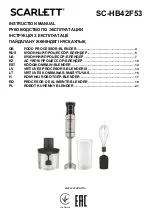
Page 130: ...08 06 2017 ABB Drives FAN V FAN U FAN W 1 2 3 K11 1 A2 A1 13 14 Q11 1 2 1 4 3 21 22 33 34 41 42 X13 3 2K X13 4 X13 5 2K X13 6 DC BUS Q10 1 1 3 5 7 8 6 4 2 1 2 P11 1 X1 X2 GREEN Load OK DOOR V1 1 U1 1 GND GND1 1 1PE 1PE I1V60 14J I1V50 X13 3 14D X13 4 X13 5 14D X13 6 R1 1 1 2 3 R3 1 1 2 3 R2 1 1 2 3 R4 1 1 2 3 Q10 1 2 4D Q10 1 1 2H Q10 1 2 7D Q10 1 1 8D MAIN CIRCUIT CHARGING CIRCUIT R10 1 X22 12 1 ...

Page 131: ...001 12G X21 5 1 040 3K X21 2 1 040 3K X22 1 15 1 13 X22 1 3 X22 1 11 2 12 X22 1 5 3AXD10000371496 020 040 020 DWG ACS880 604 0750 3 C183 1xR8i DBU with DC switch Aux voltage distribution Circuit Diagram EN Vanin Oleg 08 06 2017 Asikainen Mika 08 06 2017 ABB Drives EXTERNAL SUPPLY FOR MODULES HEATERS F95 2 4 3 1 I I 12 14 11 K95 22 24 21 12K HEAT CTRL L 6E HEAT CTRL N 6F 22 24 21 12J K95 A1 A2 HEAT...

Page 132: ...1 1 RUNNING RO1 RUNNING_60 RO2 1 NO FAULT RO2 FAULT_60 DEFAULT OUTPUT DESIGNATION AO1 AO2 0 4 20mA DEFAULT INPUT DESIGNATION AI1 0 2 10V 10V 10V AI2 0 4 20mA AO1 0 20mA RL 500 ohm AO1 NOT IN USE_60 AI1 0 2 10V AI1 NOT IN USE_60 DEFAULT INPUT DESIGNATION DI1 DI6 DIIL NOMINAL VOLTAGE 24VDC DEFAULT INPUT OUTPUT DESIGNATION DI2 DI2 NOT IN USE_60 DI4 DI4 NOT IN USE_60 DI5 DI5 NOT IN USE_60 DI6 1 RESET ...

Page 133: ... by navigating to www abb com searchchannels Product training For information on ABB product training navigate to new abb com service training Providing feedback on ABB manuals Your comments on our manuals are welcome Navigate to new abb com drives manuals feedback form Document library on the Internet You can find manuals and other product documents in PDF format on the Internet at www abb com dr...

Page 134: ...www abb com drives 3AXD50000022033D 2019 ABB Oy All Rights Reserved Specifications subject to change without notice 3AXD50000022033 Rev D EN EFFECTIVE 2019 09 30 ...

Reviews: