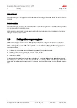
background image

ABB Turbocharging

Operation Manual

A145-M56

HT538538 English

Original Operation Manual

Chapter

Document-ID

1

Introduction

HZTL4005_EN_E

2

Safety

HZTL4022_EN_D

3

Safety data sheet

HT538538

4

Product description

HZTL4031_EN_E

Summary of Contents for A145-M56

Page 1: ...arging Operation Manual A145 M56 HT538538 English Original Operation Manual Chapter Document ID 1 Introduction HZTL4005_EN_E 2 Safety HZTL4022_EN_D 3 Safety data sheet HT538538 4 Product description HZTL4031_EN_E ...

Page 2: ...als and the corresponding operating limits in chapter 3 are jointly defined with the enginebuilder This information is specific to the product Non observance of the recommended replacement intervals and the operating limits increases the risk of unpre dictable component failures ...

Page 3: ...ents Page 1 8 Copyright 2016 ABB All rights reserved HZTL4005_EN Revision E July 2016 Introduction 1 Introduction 3 1 1 Purpose of the manual 3 1 2 Symbols definitions 4 1 3 Storage of new turbochargers and spare parts 6 1 4 Contact information 8 ...

Page 4: ......

Page 5: ...plains the turbocharger and contains instructions for safe operation The Operation Manual is a complement to and expansion of existing national regulations for occupational safety accident prevention and environmental protection Target group The Operation Manual is aimed at engineers and trained mechanics responsible for the proper operation of the engine and for the turbocharger connected to it A...

Page 6: ...rk Definition of mandatory signs Mandatory signs show the protective equipment to be worn for a task The mandatory signs are described in chapter Safety and must be complied with Definition of Caution Warning Caution and warning signs are described in chapter Safety ABB Turbo Systems ABB Turbo Systems Ltd is identified as ABB Turbo Systems in this document Official service stations of ABB Turbo Sy...

Page 7: ...eaning Pictogram Meaning Tighten with specified torque Affix Tighten over specified tightening angle Measure Hand tight tighten without tools Note Oil Visually inspect Apply screw locking paste e g Loctite Please note text for numbered work step Apply high temperature grease See document Apply other paste in accordance with specifications Dispose of in an environmentally compatible professional wa...

Page 8: ...of the Ordinance on Hazardous Substances Nevertheless the following points must be observed when handling VCI Observe the information in the material safety data sheet Ensure proper space ventilation Do not eat drink or store food at the workplace while working with VCI Clean hands and face after working with VCI For more information see www branopac com Wear safety gloves to protect against mecha...

Page 9: ...y an ABB Turbocharging Service Station Check the package for damage If the package is damaged the turbocharger or cartridge group must be checked and repackaged by an ABB Turbocharging Service Station After every 3 years the following steps must be carried out by an ABB Turbocharging Service Station Checking the component Replacing the desiccant Repackaging the component NOTICE Replacement compone...

Page 10: ...hts reserved HZTL4005_EN Revision E July 2016 1 4 Contact information Contact information of the ABB Turbocharging Service Stations is available online Scan the QR code to access our website ABB Turbo Systems Ltd Bruggerstrasse 71a CH 5401 Baden Switzerland www abb com turbocharging ...

Page 11: ...ion of mandatory signs 4 1 4 Definition of safety instructions 4 1 5 Intended use 5 1 6 Deflagration on gas engines 6 1 7 Warning plates on the turbocharger 7 1 8 Turbocharger rating plate 8 1 9 Periodic check of the pressure vessels 9 1 10 Lifting of loads 10 1 11 Prerequisites for operation and maintenance 11 1 12 Hazards during operation and maintenance 12 1 13 Safe operation 14 1 14 Safe maint...

Page 12: ......

Page 13: ...uence of insufficient compliance with safety instructions Are a consequence of insufficient or inappropriate performance of maintenance and in spection work The operating company is responsible for defining measures that regulate safe access to and safe handling of the turbocharger All instructions contained in this chapter must be observed for safe and trouble free operation of the turbocharger a...

Page 14: ...ask to protect against Dusts Gases Safety helmet Ear protection Table 2 Personal protective equipment to be worn specific to the respective task 1 4 Definition of safety instructions WARNING Definition of Warning Non compliance or inaccurate compliance with working or operating instruc tions indicated by this symbol and the word WARNING can lead to serious injuries to personnel and even to fatal a...

Page 15: ... pressure required for operation The turbocharger is solely intended to be operated with a clockwise direction of rotation as viewed from the turbine end The specific operating limits of the turbocharger were determined on the basis of information from the enginebuilder about the intended use These data are given on the rating plate ABB accepts no liability and rejects all warranty claims for any ...

Page 16: ...charger or improper operation 1 6 Deflagration on gas engines ABB turbochargers can tolerate a deflagration with a transient pressure increase of 12 bar After a deflagration event ABB Turbo Systems recommends verifying the following points on the turbocharger Position of the turbine and compressor casings to the bearing casing Shifting of the bearing casing in relation to the bracket Cracks in cas...

Page 17: ... be present in the intended locations and must be legible Figure 1 Warning plate If warning plates are not present in the intended locations or are not legible they must be re placed with new warning plates The necessary information can be found in the Operation Manual Chapter 4 Product description Turbochargers supplied to the enginebuilder without insulation must be equipped later with warning p...

Page 18: ...reed with the en ginebuilder 02 Turbocharger operating limits during operation Recommended inspection and replacement intervals of turbocharger components 03 Inspection interval of plain bearings in 1000 h 04 Replacement interval of compressor in 1000 h 05 Replacement interval of turbine in 1000 h Further data 06 Customer part number 07 Designation for special design 08 Weight of turbocharger in k...

Page 19: ...x and tMmax is not permitted Non observance of the recommended inspection and replacement intervals increases the risk of unpredictable component failures Locations of the rating plates The locations of the rating plates are defined in the Operation Manual Chapter 4 Product de scription 1 9 Periodic check of the pressure vessels The pressure vessels used by ABB Turbocharging such as those for wet ...

Page 20: ...t against mechanical hazards Wear safety helmet Figure 3 Attachment of loads on the crane hook Figure 4 Attachment angle If there are two or more suspension points the attachment angle of 45 must not be exceed ed This prevents excessive loading due to diagonal pull Before looping around the components of the turbocharger let them cool down maximum 80 C Attach components of the turbocharger as desc...

Page 21: ...table working materials and personal protective equipment must be kept in a perfect condi tion Only authorised personnel may remain in the vicinity of the turbocharger when the engine is running Competence of personnel The turbocharger must only be operated and serviced by trained and authorised personnel Basic mechanical training is a prerequisite Modifications to the turbocharger Modifications t...

Page 22: ...g always wear ear protection Always wear ear protection if the sound pressure level exceeds 85 dB A Wear ear protection Hazards due to hot surfaces Surfaces of the turbocharger attached parts and operating fluids lubricating oil get hot during operation The surface temperature depends on the efficacy of the existing insulation The temperature may rise to a level that can cause burns WARNING Danger...

Page 23: ... protect against thermal hazards Hazards due to rotating parts WARNING Physical hazards Contact with rotating parts can cause severe injury The turbocharger must never be used without the filter silencer or the air suction branch With the engine stopped the rotor can rotate due to the stack draught alone Operate the turbocharger in compliance with the specifications Secure the rotor against uninte...

Page 24: ...lectrical installations Do not carry out any tests with regard to insulation resistance or voltage on the electrical components 1 13 Safe operation Mechanical hazards during operation During standard operation no mechanical hazards are caused by the turbocharger itself if it has been properly installed Safety during commissioning and operation Visually inspect your working environment before start...

Page 25: ...ion and insulation can cause serious injuries to persons or even fatal accidents Only operate the turbocharger with burst protection fitted and insulation fitted in one of the following permitted variants Figure 5 Variant A Insulation 01 with integrated burst protection from ABB Turbo Systems Variant B Burst protection 03 and insulation 02 from ABB Turbo Systems Variant C Burst protection 03 from ...

Page 26: ...ch you have received instruction or train ing Wear safety footwear to protect against mechanical hazard and risk of fall ing Wear protective clothing WARNING Risk of falling When working on the turbocharger there is a risk of falling Do not climb onto the turbocharger or onto attached parts and do not use them as climbing aids Use suitable climbing aids and working platforms for work above body he...

Page 27: ... Safety during disassembly assembly maintenance and repair Observe the procedures for set up service and inspection work and the inspection inter vals Inform the operating staff before starting any service or repair work Make sure the engine is not started while work is being conducted on the turbocharger Before taking off any cover or removing any guard from the turbocharger switch off the engine...

Page 28: ...have previously received instruc tion or training Hazards due to operating materials and supplies Operating materials and supplies are substances required for the operation of the turbo charger or for the performance of maintenance work Oils greases coolants detergents and solvents acids and similar substances can be classified as hazardous substances WARNING Handling operating materials and suppl...

Page 29: ...ation in the material safety data sheet for the operating materials and supplies Comply with local legislation Hazards due to the handling of insulation materials WARNING Danger from insulation materials Dust or fibres from insulation materials can have adverse effects on the health or cause irritations Unsuitable and combustible insulation materials are a fire hazard Only use suitable and non com...

Page 30: ......

Page 31: ...Operation Manual A145 M56 Safety data sheet Page 1 1 Safety data sheet Copyright 2017 ABB All rights reserved HT538538 February 2017 A145 M56 HT538538 A145 M56 HT538538 577 630 548 600 750 8 50 50 2013 ...

Page 32: ......

Page 33: ...urbocharger 12 2 3 Installing the turbocharger 16 3 Commissioning 23 3 1 Oil supply 23 3 2 Inspection procedures 25 3 3 Commissioning after taking out of operation 27 4 Monitoring operation 29 4 1 Oil pressure oil temperature 29 4 2 Exhaust gas temperature before turbine 31 4 3 Turbocharger speed 32 5 Operation and service 35 5 1 Noise emission 35 5 2 Service work 37 5 3 Expected replacement inter...

Page 34: ...vice support 90 8 11 Axial clearance A and radial clearance B 91 8 12 Nozzle ring compression PD 92 8 13 Installing nozzle ring 93 8 14 Installing the cartridge group 94 8 15 Installing the compressor casing 97 8 16 Radial clearances N and R 99 8 17 Installing air inlets 100 8 18 Installing the gas outlet flange 101 8 19 Installing the gas outlet casing 103 8 20 Table of tightening torques 105 9 T...

Page 35: ... Table of contents Page 3 121 Copyright 2017 ABB All rights reserved HZTL4031_EN Revision E January 2017 12 1 Ordering spare parts 115 12 2 Required customer spare part set 97070 115 12 3 View of turbocharger with part numbers 116 Figures 119 Tables 121 ...

Page 36: ......

Page 37: ... on questions regard ing a design variant see Contact information at www abb com turbocharging Accuracy of illustrations The illustrations in this document are general in nature and intended for ease of understand ing Differences in detail are therefore possible 1 2 Registered trademarks The trademarks of outside companies are used in this document These are marked with the symbol 1 3 Related docu...

Page 38: ...and function of the turbocharger Figure 1 Layout and function of the turbocharger 01 Filter silencer air suction branch 08 Gas outlet flange 02 Compressor casing 09 Nozzle ring 03 Diffuser 10 Turbine casing 04 Bearing casing 11 Turbine end bearing flange 05 Axial thrust bearing 12 Compressor end bearing flange 06 Radial plain bearing 13 Compressor wheel 07 Turbine ...

Page 39: ...gine cylinders The rotor runs in two radial plain bearings 06 which are located in the bearing casing 04 between compressor and turbine The axial thrust bearing 05 is located between the two radial plain bearings The plain bearings are connected to a central lubricating oil duct which is normally supplied by the lubricating oil circuit of the engine The oil outlet always lies at the deepest point ...

Page 40: ...plates are not present in the designated locations or not readable proceed as fol lows Order new warning plates from ABB Turbocharging Service Stations Remove any warning plates that have become unreadable Clean and degrease the areas designated for the warning plates Fit new warning plates and remove protective sheets Turbochargers supplied to the enginebuilder without insulation must be equipped...

Page 41: ...on Page 9 121 Copyright 2017 ABB All rights reserved HZTL4031_EN Revision E January 2017 1 6 Locations of the rating plates Figure 4 Locations of the rating plates One rating plate 01 each is attached on the left and the right side of the turbocharger bearing casing ...

Page 42: ......

Page 43: ...e turbo charger The following weight specification applies to the heaviest variant possible Depending on the specification the weight specified on the rating plate may be lower than the standard value specified here Product Weights kg A130 M 200 A135 M 280 A140 M 470 A145 M 770 Table 2 Weights of turbochargers A130 M A145 M Figure 5 Suspension of complete turbocharger unit A Turbocharger with oil ...

Page 44: ...om pressor wheel cooling opening with a screw plug 01 If present Disconnect the plug to the speed sensor 86505 and secure the rolled up cable on the turbocharger This protects the plug from being crushed Figure 6 Removing the turbocharger A Oil cooled bearing casing D Clamping nut B Water cooled bearing casing E Standard nut C Position of expansion sleeves Treat the stud 02 and nut with penetratin...

Page 45: ...ure must be chosen to undo the connection Oil cooled bearing casing A Attach lifting gear to the suspension eye Loosen and remove nuts E If clamping nut D is present Loosen in accordance with chapter Loosening the clamping nut 14 Positioning the turbocharger for storage 15 Water cooled bearing casing B Loosen and remove water connections Close the openings of the water connections with screw plugs...

Page 46: ...teps for loosening the pressure screws CAUTION Do not clean pressure screws The pressure screws are equipped with a permanent sliding layer that must not be removed Do neither clean nor lubricate the pressure screws In case of non compliance it cannot be ensured that the necessary tension force is reached Do not clean pressure screws Do not lubricate pressure screws Figure 7 Loosening the clamping...

Page 47: ...ed stably it may tip over This can result in serious personal injury Place the turbocharger on a clean level support Secure the turbocharger to prevent it from tipping over by using wooden beams and wedges and by taking the centre of gravity into account Figure 8 Turbocharger centre of gravity 01 Centre of gravity Remove turbocharger from engine support set it down properly in an appropriate place...

Page 48: ... is provided by O rings The O rings are not included in the ABB Turbo Systems scope of delivery Figure 9 Inserting gaskets into the bracket 01 Bracket 04 Slot for O ring 02 Oil supply 05 O rings 03 Oil drain 06 Pin optional Pin 06 as installation safety device Turbochargers can have an oil inlet either on their right or left side the oil inlet position can be different for the turbocharger fitted ...

Page 49: ...aded rods Figure 11 Requirements for threaded rods Product Diameter Threaded rod mm Material DIN ISO 898 Part 1 Thread length L1 mm Length of threaded rod Oil cooled L2 mm Water cooled L2 mm A130 Ø 16 M16 10 9 12 9 30 250 250 A135 Ø 20 M20 10 9 12 9 30 270 325 A140 Ø 24 M24 10 9 12 9 70 350 360 410 420 A145 Ø 30 M30 10 9 12 9 80 415 425 Table 3 Requirements for threaded rods Fastening material sco...

Page 50: ...shes 42190 4 Attach the lifting gear to the suspension eye of the bearing casing A B and loop around the gas outlet casing 61001 If the gas outlet casing is already fitted in the exhaust gas pipe the attachment of the lifting gear on the bearing casing is sufficient 5 Position the turbocharger on the bracket 04 and align it Pay attention to the positioning pins 05 in the bracket 6 When fixing with...

Page 51: ...tening the turbocharger with a standard nut Fit the nuts and tighten them according to variant 1 or 2 in the table below When the turbocharger is mounted on the engine support the bolt threads and screw heads must be lightly oiled assumed friction coefficient µ 0 12 for tightening torque Product Through hole in bearing casing mm Fixing screws mm Variant 1 Tightening torques Nm Variant 2 Hydraulic ...

Page 52: ... screws Do not lubricate pressure screws In order to correctly fit the clamping nuts the pressure screws 04 must not protrude from the clamping nuts 03 in the direction of the thrust washer 02 Make sure the pressure screws do not protrude in the direction of the thrust washer Figure 13 Preparing the clamping nut for the tightening procedure 1 Check whether the expansion bushes 42190 with recess ar...

Page 53: ...A145 M30 45 Table 5 Pressure screw tightening torques 1 Screw in pressure screws crosswise by hand until reaching the stop 2 Tighten pressure screws crosswise to 50 of the tightening torque specified in the table 3 Tighten pressure screws crosswise to 100 of the tightening torque specified in the table 4 Work in a circle to tighten all pressure screws to 100 of the tightening torque specified in t...

Page 54: ...instructions of the enginebuilder Version with compressor wheel cooling CAUTION Failure of compressor wheel cooling Any prolonged failure of the compressor wheel cooling will shorten the re placement interval of the compressor wheel Make sure there is an uninterrupted supply of cooling air during operation Figure 15 Connecting the compressor cooling air intake Remove the screw plug on the connecti...

Page 55: ...uilder s specifications regarding the selection of lubricating oil and the oil change intervals 3 1 2 Pre lubrication Pre lubrication must be carried out as follows Switch on the oil pump Build up oil pressure see Table 6 Do not exceed a pre lubrication time of 2 minutes Start the engine Let the oil pump run until the pump driven by the engine generates sufficient pressure 3 1 3 Oil filtering Filt...

Page 56: ...rved HZTL4031_EN Revision E January 2017 3 1 5 Oil orifice in the bearing casing Figure 17 Oil orifice 01 Bearing casing 02 Oil orifice 03 Circlip With an oil inlet pressure of more than 3 bar with engine under load before the turbocharger the bearing casings are equipped as standard with an orifice at the oil inlet ...

Page 57: ...perty can be caused by dirt and solid mate rial particles in the oil For the initial commissioning phase and after all service work flush the complete lubricating system with warm oil Use special running in filters when running in the engine and after all ser vice work on the lubricating system Check that the oil filter is clean before commissioning Check the oil pressure in the oil supply pipes W...

Page 58: ...inlet Keep to the lubricating oil temperature at the inlet Refer to chapter Monitoring operation 29 for admissible values Tightness of pipes Check all the pipes for tightness 3 2 4 Checks when starting up the engine Measure speed oil pressure and charging pressure at various engine performances Measure the exhaust gas temperature before and after the turbine Measure the air temperature before and ...

Page 59: ...rsion with compressor wheel cooling Remove the screw plug on the cooling air connection and fit the cooling air line General Check the exhaust gas pipe before and after the turbine for combustion residues or water residues and clean it Remove any foreign objects that may be present Check and clean filter silencer or air supply line and remove any foreign objects that may be present Put engine side...

Page 60: ......

Page 61: ...upstream of orifice bar Normal operation 2 0 poil 4 5 Engine start Cold oil admissible for maximal 15 minutes 8 0 Engine idling admissible for maximal 1 hour 0 5 poil 2 5 Pre lubrication and post lubrication engine stopped 0 5 poil 1 0 Warning signal n 0 5 x nBmax 1 25 Alarm signal Not admissible Stop the engine immediately 0 6 Table 6 Lubricating oil pressure oil inlet 01 Turbocharger contact sur...

Page 62: ...the outlet The oil temperature at the outlet is mainly dependant on Lubricating oil temperature and pressure at the oil inlet Engine load and turbocharger speed Exhaust gas temperature The maximum admissible oil temperature at the outlet is listed in the following table The spec ified oil outlet temperature is to be considered as alarm value for the turbocharger operation and must be monitored acc...

Page 63: ...lacement intervals Operation above the operating limits defined on the rating plate can shorten the recommended replacement intervals considerably Measure exhaust gas temperature upstream of turbine Comply with operating limits on rating plate Definition and explanations concerning rating plate refer to chapter 2 of Operation Manual Safety Operating limits refer to chapter 3 of Operation Manual Sa...

Page 64: ...bocharger speed CAUTION Do not strain cables If you pull the speed measurement cables too hard contacts can be pulled out Do not strain the speed measurement cables by pulling 4 3 2 Layout and overview Figure 18 Layout and overview of speed measurement system 86505 Speed sensor 42188 Screw plug 86515 Cable connector 42189 Gasket 86526 F I converter 01 Plug with integrated voltage limiter 86528 Tac...

Page 65: ...cannot be stopped it can continue to be driven at this reduced engine load or turbocharger speed If a turbocharger surges continuously the engine performance must be reduced further Measure the temperatures in the air lines and gas piping from and to the turbochargers and compare with normal values If clear deviations of temperature are found the nearest ABB Turbocharging Service Station has to be...

Page 66: ...and an O ring No additional gasket is required during assembly Figure 19 Replacing the speed sensor Part number A130 A135 A140 A145 86505 M12 x 1 5 15 Nm M12 x 1 5 15 Nm M12 x 1 5 15 Nm M12 x 1 5 15 Nm Table 9 Tightening torque 86505 Reduce the engine performance to idling and then stop the engine Pay attention to post lubrication Stopping the engine 43 Switch off the lubricating oil supply to the...

Page 67: ... is measured at a distance of 1 meter from the turbocharger The highest value of the emission sound pressure level1 reaches a maximum of 105 dB A near the filter silencer The following prerequisites must be fulfilled with regard to the turbo charger to observe this limit value Air inlet system has been fitted All standard noise reducing measures2 have been fitted Bellows at the air outlet has been...

Page 68: ...yright 2017 ABB All rights reserved HZTL4031_EN Revision E January 2017 Suggestion for noise insulation bellows Figure 20 Noise insulation bellows 01 Compressor casing 02 Bellows 03 Charge air duct scavenging air duct 04 Insulation cushion 05 Insulation mat at least 15 mm 06 Sheet metal cover ...

Page 69: ...d or performed too late can cause excessive contamination wear and operating failures Carry out the service work at the specified time intervals CAUTION Shortened service intervals Exceptional stresses such as several starts stops per day harsh environ mental conditions poor fuel quality or high system vibrations can lead to un timely machine damage even if the prescribed service intervals are ob ...

Page 70: ...urs after commissioning Clean or replace the oil filter located in the supply pipe to the turbocharger while the en gine is stopped 5 2 3 Service work according to instructions of enginebuilder Clean or replace the oil filter located in the supply pipe to the turbocharger while the en gine is stopped 5 2 4 Service work according to data on the rating plate Usually after 8000 12000 operating hours ...

Page 71: ... ABB All rights reserved HZTL4031_EN Revision E January 2017 5 2 5 Other service work If a protective grid is installed in the gas outlet casing 61001 by ABB Turbo Systems Figure 21 Replacing the protective grid Remove the protective grid 61205 after 50000 hours and replace it with a new protective grid ...

Page 72: ...charger The following operating data and measured values must be entered regularly in the engine logbook of the enginebuilder Rating and speed of the engine Air intake temperature Pressure of the charge air Pressure loss in the charge air cooler Lubricating oil pressure and lubricating oil temperature If present Speed of the turbocharger Air temperature after the compressor and after the charge ai...

Page 73: ...ing the bearing parts and replacing the non rotating components exposed to hot gas A decisive role is played by various influencing parameters which in extreme cases can dras tically shorten the replacement interval of these parts During the prescribed periodic service work the individual parts are examined for wear and replaced if necessary Expected replacement intervals h GAS MDO HFO Turbine cas...

Page 74: ...e following influences Fuel quality and fuel treatment Load profile thermal cycling also number of starts stops emergency shutdowns operat ing point Gas inlet temperature Frequency and execution of cleaning process during operation Turbocharger specification System specific operating conditions combustion quality exhaust gas composition For bearing parts Lubricating oil quality oil filtering oil c...

Page 75: ...d for engine idling see Table 6 Post lubricate water cooled bearing casings until the rotors come to a standstill Deactivate post lubrication as soon as the rotor comes to a standstill Deviating procedures must be coordinated with ABB Turbo Systems For oil cooled bearing casings post lubricate for 20 minutes if the turbine inlet temperature tTE exceeds the following values when the engine is stopp...

Page 76: ......

Page 77: ...to be kept low while ensuring maximum fuel efficiency Maintenance interval Maintenance work Operating status 24 72 h 1 Cleaning the compressor during operation 46 Engine load 50 85 50 200 h 1 Cleaning the turbine during operation 50 Engine load 20 40 guideline value Similar to the service interval usually every 8000 12000 h 2 Cleaning components mechanically 54 Engine stopped Table 11 Maintenance ...

Page 78: ...taminated components cleaned mechanically by an ABB Turbocharging Service Station Periodic cleaning during operation does not replace the service work where the turbocharger is completely dismantled and serviced by an ABB Turbocharging Service Station Causes and results of contamination Contamination of the compressor stage depends on the degree of purity of the sucked in air Deposits can form in ...

Page 79: ...perating periods in the lower range of performance that both turbocharger compressors are cleaned 6 2 4 Function and safety of wet cleaning CAUTION Volume of water Uncontrolled volumes of water can damage the turbocharger and the en gine Never connect injection tubes directly to a water pipe or a larger metering container other than that specified by ABB Turbo Systems WARNING Danger due to pressur...

Page 80: ... filter silencer or air suction branch 02 Pressurized air inlet pipe 03 Valve activator Pressurized air from the compressor casing 72000 of the turbocharger passes through the pipe 02 to the water pressure vessel 27000 As soon as the valve activator 03 is activat ed water is pressed into the pipe 01 and routed to the filter silencer or air suction branch The water does not act as a solvent The coa...

Page 81: ...Parameters for wet cleaning of compressor Remove sealing plug 27005 Fill container with 0 4 dm3 of pure water Screw in sealing plug 27005 again Push the valve activator 03 against the spring and hold for 10 15 seconds until the entire volume of water is injected Continue to operate the engine for at least five minutes to ensure that all of the water is flushed out of the system Not more than three...

Page 82: ...ace the service work where the turbocharger is completely dismantled and serviced by an ABB Turbocharging Service Station Cause and consequences of contamination ABB Turbo Systems recommends the use of fuels with low ash sulphur sodium and vanadi um contents The combustion of heavy fuel oil HFO in diesel engines causes contamination of the turbine stage Poor quality fuel in conjunction with high e...

Page 83: ...aning process with multiple short injection periods A turbine cleaning procedure with multiple short injection periods is recom mended only under certain circumstances If such a procedure is to be used this must be coordinated with ABB Turbo Systems Contact ABB Turbo Systems CAUTION Corrosion and deposits when cleaning Salt water and cooling water treatment substances damage and adversely affect t...

Page 84: ...s tem perature after the cylinder This must be taken into account when setting the operating point before cleaning If necessary the engine performance must be reduced to meet these conditions The cleaning cycle can be started when the above conditions are fulfilled 6 3 6 Carrying out wet cleaning of the turbine CAUTION Inadmissible thermal stress and flooding of the turbine Smaller amounts of wate...

Page 85: ... valve 02 after 10 minutes Wait for 10 minutes do not change the load during this stabilisation phase If the cleaning result is unsatisfactory or there is water leakage contact an ABB Turbocharg ing Service Station Product Temperature before turbine before clean ing C Maximum tempera ture before turbine during cleaning C Water volume flow VW dm3 min 1 Injection time min A130 350 430 530 4 0 10 A13...

Page 86: ...re sensitive and easily sustain mechanical dam age The use of needle descalers for example or other striking tools dam ages the components Depending on the specification nozzle rings or tur bine casings may have protective coatings which can also be damaged Use only soft tools such as rags brushes or wire brushes In case of heavy contamination the cleaning methods described in this chapter such as...

Page 87: ...filter ring if present Remove filter ring 81265 Clean filter ring 81265 as required or every 500 hours of operation and replace after the fifth cleaning process at the latest Contamination of the filter ring depends on the degree of purity of the sucked in air Rinse the filter ring 81265 with water and mild detergent or in the case of heavy contam ination soak and carefully push through Rinse in c...

Page 88: ...ion segments 81136 must only be cleaned lightly with compressed air a soft brush or a moist cleaning cloth Have any heavily contaminated absorption segments replaced by an ABB Turbocharging Service Station Fitting the filter silencer see Figure 24 Insert the absorption segments 81136 into the sheet metal coverings 81137 Bend the sheet metal coverings 81137 back to their original shape and insert i...

Page 89: ...rding to the material safe ty data sheet Comply with local legislation Wear safety goggles Wear safety gloves to protect against chemical hazards Wear a respiratory mask to protect against gases The following parts which are relevant in terms of performance can be cleaned in accordance with the description below Figure 25 Compressor end non rotating parts 72000 Compressor casing 77000 Wall insert ...

Page 90: ...ly with local legislation Wear safety goggles Wear safety gloves to protect against chemical hazards Wear a respiratory mask to protect against gases Baked layers of contamination for example from heavy fuel oil or coked oil occur at the tur bine end The following parts which are relevant in terms of performance can be cleaned in accordance with the description below Figure 26 Turbine end non rota...

Page 91: ...y after clean ing parts may corrode Immediately after cleaning install the cartridge group and put it back into operation There can be severe contamination of the compressor wheels due to badly filtered suction air and of the turbines because of heavy fuel oil operation or carbonized oil Cleaning during op eration may not suffice to remove such contamination instead it may need to be cleaned me ch...

Page 92: ...ntamination penetrates the cartridge group this can impair the function of the turbocharger and damage parts inside the cartridge group Make sure that no water or contamination can enter into the cartridge group Clean the compressor wheel with a rag or soft brush which has been soaked in water with a household cleaning agent Do not use wire brushes Dry the compressor wheel and the gap between the ...

Page 93: ...n the following Figure 27 Soaking the turbine end Product A mm B mm C mm A130 108 17 205 A135 128 20 245 A140 157 25 300 A145 187 30 357 Table 15 Value table for soaking To soak the layers of contamination on the turbine the cartridge group can be immersed verti cally in a container 02 with fluid Place the container 02 inside a larger container 03 so that the overflowing fluid can be collected CAU...

Page 94: ...harger and damage parts inside the cartridge group Place the cartridge group on suitable supports 01 made of wood or met al Observe dimension B for the supports 01 so that the cartridge group is not immersed too deeply Let the layers of contamination on the turbine soak for four hours Removing dirt WARNING Health hazard due to soot particles If soot particles enter the eyes or respiratory tract th...

Page 95: ...posits lead to rotor unbal ance This can result in bearing or turbocharger damage Remove all traces of contamination from the turbine After brushing off the dirt fill the container 02 with clean water and not with salt water Immerse the turbine of the cartridge group in clean water so that any loose dirt comes off Lift up the cartridge group and align it horizontally Clamp the partition wall to th...

Page 96: ......

Page 97: ... enginebuilder Turbocharger Rotor unbalance Contact ABB Turbocharging Service Station Turbine or compressor damaged Bearing damaged Table 17 Malfunctions when starting Vibrations Rubbing of rotating parts Normal behaviour not a malfunction Turbocharger A minimal and uniform wear at the circumference of the rotor components caused by slight local rubbing against adjacent components is permitted Thi...

Page 98: ...ace Manometer displays incorrectly Replace manometer Turbocharger Axial clearance of the rotor excessive Contact ABB Turbocharging Service Station Table 19 Malfunctions during operation Lubricating oil pressure too low Speed reduces Possible causes Remedy Engine Defect on the connected cylinders in pulse charging Contact enginebuilder Turbocharger Turbine and or nozzle ring severely con taminated ...

Page 99: ...ter too high Check clean cooling system Insufficient ventilation Improve ventilation Table 22 Malfunctions during operation Exhaust gas temperature too high Charge air pressure too low Engine performance and engine speed unchanged suction condition normal Possible causes Remedy Engine Air receiver not sealed Repair Gas piping between engine and turbine not sealed Injection mistimed Set correctly V...

Page 100: ...rely contaminated or corroded compressor wheel can reduce the compressor wheel s fatigue endurance limit and result in the turbocharger being damaged Rectify malfunction in accordance with the following table Possible causes Remedy Turbocharger Compressor components severely con taminated by the ventilation gases that have been fed in Clean see chapter Periodic maintenance work 45 Optimize oil sep...

Page 101: ...e clarified and remedied immediately by an ABB Turbo charging Service Station Have parts assessed for damage and if necessary replaced by an ABB Turbocharging Service Station Possible causes Remedy Engine Protective grating in front of the turbo charger contaminated or damaged Clean replace Turbocharger Filter silencer or diffuser contaminated Clean see chapter Periodic maintenance work 45 Heavy c...

Page 102: ...e 28 Malfunctions when stopping Runout noises Runout time too short The runout time must be noted down as a reference Because the runout time depends on the oil viscosity the runout time must always be measured at the same oil temperature If the runout time is significantly shorter in comparison to a previous measurement the follow ing table must be observed Possible causes Remedy Turbocharger Tur...

Page 103: ...o chapter Ordering spare parts 115 Replacing the speed sensor 34 Table 30 Malfunction of the speed measurement system No signal or poor signal amplitude Measured speed too high Possible causes Remedy Turbocharger Sensor tip contaminated since it is magnetic and can attract metallic particles This reduces the distance to the signal emitting sealing disc which can lead to amplification of the noise ...

Page 104: ......

Page 105: ...rbocharger to cool down before carrying out any work Wear safety gloves to protect against thermal hazards WARNING Cutting injuries when working on the turbocharger Some parts on the turbocharger may have sharp edges There is a risk of a cutting injury Wear safety gloves against mechanical risks when conducting assembly and disassembly work Wear safety gloves to protect against mechanical hazards ...

Page 106: ...amaged assembly devices must no longer be used and must be re placed Customer spare part set Before starting operations make sure the required customer spare part sets are available See chapter Spare parts 115 Oil orifice When disassembling the turbocharger an oil orifice fitted in the oil inlet must not be re moved see also chapter Removing the cartridge group 87 Tightening torques for components...

Page 107: ...on point Defined loading point on a component or an assembly blind hole thread eyelet lug Assembly device Devices that are fitted on the turbocharger in order to obtain a suspension point Assembly devices are specially constructed and designed for the defined use they are not commer cially available products Use assembly devices only for the described applications Lifting gear Equipment for the li...

Page 108: ... rights reserved HZTL4031_EN Revision E January 2017 Two ring nuts are required for safer lifting of the cartridge group which are not included in the ABB Turbo Systems scope of delivery Ring nuts to be used VRM Product Thread Starpoint ring nut VRM A130 M16 A135 M16 A140 M16 A145 M16 Table 34 Ring nuts to be used ...

Page 109: ...on A130 kg A135 kg A140 kg A145 kg 01 Filter silencer 19 30 40 65 02 Radial air suction branch 6 8 13 21 03 Axial air suction branch 4 5 6 9 04 Compressor casing 24 40 60 95 05 Wall insert 6 8 15 24 06 Diffuser 3 4 7 11 07 Cartridge group 40 60 110 180 08 Nozzle ring 2 2 4 6 09 Burst ring 2 3 5 12 10 Turbine casing 1 inlet 50 75 135 210 Turbine casing 2 inlets 45 65 125 190 Turbine casing 3 inlets...

Page 110: ... 3 Removing air inlets Mark the casing position for assembly Figure 29 Removing air inlets 1 Attach lifting gear to the filter silencer 81000 or air suction branch 82000 2 Loosen and remove V clamp 72020 3 Remove filter silencer 81000 or air suction branch 82000 set it down properly in an appropriate place and secure it 4 Remove and dispose of the O ring 81010 82010 ...

Page 111: ... 8 Dismantling and fitting Page 79 121 Copyright 2017 ABB All rights reserved HZTL4031_EN Revision E January 2017 8 4 Removing the gas outlet casing Removing the insulation Figure 30 Removing the insulation Remove the insulation of the gas outlet casing ...

Page 112: ...y 2017 Mark the casing position for assembly Figure 31 Removing the gas outlet casing 1 Attach lifting gear to the gas outlet casing 61001 2 Loosen and remove nuts 51009 3 If present Loosen the support 61301 from the bracket 4 Remove the gas outlet casing 61001 set it down properly in an appropriate place and secure it 5 Remove and dispose of the gasket 61002 ...

Page 113: ...gas outlet flange Depending on the way of fixing the gas outlet flange the appropriate Working Instruction has to be consulted pressing off using 3 or 6 press off screws If the following Working Instructions are not observed this can lead to cracks in the gas outlet casing The following variants are possible Pressing off using 3 press off screws Pressing off using 6 press off screws ...

Page 114: ...er ensure that the gas outlet flange does not cant If necessary Treat the centering seat with rust remover through the press off threads and the clearance holes Mark the casing position for assembly Figure 32 Dismantling the gas outlet flange Product Press off screws to be used strength 8 8 Tightening torque A130 3 x M 8 x 20 20 Nm A135 3 x M10 x 25 40 Nm A140 3 x M12 x 30 65 Nm A145 3 x M12 x 30 ...

Page 115: ...mer ensure that the gas outlet flange does not cant If necessary Treat the centering seat with rust remover through the press off threads and the clearance holes Mark the casing position for assembly Figure 33 Removing the gas outlet flange Product Press off screws to be used strength 8 8 Tightening torque A130 6x M6 x 20 10 Nm A135 6x M8 x 25 20 Nm A140 6x M10 x 30 40 Nm A145 6x M12 x 30 65 Nm Ta...

Page 116: ... 1 Loosen screws 72011 and remove together with fastening strips 72012 2 Attach swivel lifting eye S to the compressor casing and the lifting gear 3 Remove the compressor casing 72000 and turn it 180 4 Remove and dispose of the O ring 42012 5 Loosen screws 79041 and remove from the compressor casing 72000 with fixing discs 79040 and diffuser 79000 If the compressor casing cannot be loosened it can...

Page 117: ... Revision E January 2017 Dismantling the wall insert Figure 35 Dismantling the wall insert 1 Knock the wall insert 77000 out of the compressor casing 72000 with a plastic tip ham mer 2 Attach swivel lifting eye S to the compressor casing 72000 and the lifting gear 3 Lift up the compressor casing 72000 4 Remove and dispose of the O ring 77005 ...

Page 118: ...017 8 7 Pressing off the casing CAUTION Axial force of the press off tool Using the press off tool 90042 a high level of axial force can be generated If the casing is pressed off with too much force on one side the rotor can be damaged Use the tool on both sides in alternation and make sure not to press off too hard on either side Figure 36 Press off the casing ...

Page 119: ...eets 01 02 03 Mark the casing position for assembly Do not remove oil orifice if present To limit the oil flow rate through the bearing casing during operation engine under load to the admissible values an oil orifice is mandatory at the oil inlet of the bearing casing if the oil inlet pressure is 3 bar overpressure If an oil orifice is fitted in the oil inlet of the bearing casing it must not be ...

Page 120: ... Ripp washers 51003 together with the fas tening strips 51002 Figure 40 Removing cartridge group 2 3 Insert screws from service support into cartridge group 4 Secure ring nuts VRM onto the screws with washers 5 Secure the lifting gear to the ring nuts and suspension eye as shown 6 Remove the cartridge group vertically from the turbine casing 7 Turn the cartridge group into the horizontal rotor axi...

Page 121: ...ion E January 2017 8 9 Removing the nozzle ring Figure 41 Removing the nozzle ring 1 If present Remove the metal C ring 51105 2 Position the fastening strips 51002 in place 3 Pull out the nozzle ring 56001 with the two extraction devices 90070 and the service support base 90012 4 Remove the lamellar sealing ring 56005 5 Remove the burst ring 57210 ...

Page 122: ...eserved HZTL4031_EN Revision E January 2017 8 10 Installing the cartridge group on the service support Figure 42 Installing the cartridge group on the service support 1 Remove ring nuts VRM 2 Remove service support screws 3 Fit service support 90012 according to the illustration 4 Insert the cartridge group 5 Fit the nuts ...

Page 123: ...21 0 70 1 37 A145 0 15 0 25 0 88 1 56 Table 38 Permissible clearances A and B 1 Move the rotor to and fro up to the stop In order to obtain a correct measurement elevate the turbine a little 2 Measure clearance A and compare it with the permissible values in the table 3 Raise the compressor and push the turbine down at the same time 4 Raise the turbine and push the compressor down at the same time...

Page 124: ... the heat shield 42400 and the turbine casing 51000 Figure 44 Nozzle ring compression PD Product Compression PD mm A130 0 15 0 15 A135 0 16 0 16 A140 0 16 0 16 A145 0 16 0 16 Table 39 Permitted nozzle ring compression PD 42001 Bearing casing 51000 Turbine casing 42400 Heat shield 56001 Nozzle ring 1 Measure dimensions A B and S on cleaned surfaces 2 Calculate compression PD If the calculated value...

Page 125: ...ring 56005 in the correct slot see detail A1 A2 When doing this pay attention to correct winding of the lamellar sealing ring see detail B 2 Secure the lamellar sealing ring 56005 with adhesive tape 01 3 Place the burst ring 57210 in the turbine casing 4 Insert the nozzle ring 56001 with the cams facing downwards into the turbine casing as far as it will go Align the cams on the nozzle ring with t...

Page 126: ...the cartridge group and rotating it by 90 Figure 46 Lifting the cartridge group and rotating it by 90 1 Loosen and remove nuts 2 Lift the cartridge group out of the service support 90012 3 Insert the screws of the service support from above and fit ring nuts VRM with washers 4 Attach lifting gear to the ring nuts VRM 5 Lift cartridge group at the side of the ring nuts VRM and turn it into a vertic...

Page 127: ... number A130 A135 A140 A145 51007 M8 25 Nm M10 45 Nm M12 75 Nm M12 75 Nm Table 40 Tightening torque 51007 1 Coat the threads of the studs 51006 with high temperature grease 2 Align the casing position of the cartridge group with the marking 3 Lower the cartridge group into the turbine casing 4 Remove ring nuts and screws 5 Install the fastening strips 51002 with Verbus Ripp discs 51003 and hexagon...

Page 128: ...ved A burst protection is integrated in this turbine casing insulation supplied by ABB Turbo Systems For turbochargers which were ordered from ABB Turbo Systems without in sulation or which are equipped with the insulation 02 a separate burst pro tection 03 is fitted If the insulation from ABB Turbo Systems 01 is not installed the separate burst protection 03 plus either the insulation 02 or an ap...

Page 129: ...replace the O ring 77005 see section Spare parts A130 A140 1 Fit a new O ring 77005 2 Install the wall insert 77000 in the compressor casing 3 Fit the diffuser 79000 with fixing discs 79040 and screws 79041 Observe the tighten ing torque A145 1 Fit the lifting beam 90258 to the wall insert 77000 2 Fit the swivel lifting eye S to the lifting beam Secure lifting gear to the swivel lifting eye 3 Fit ...

Page 130: ...35 Nm M10 70 Nm M12 105 Nm M14 170 Nm Table 42 Tightening torque 72011 1 Fit a new O ring 42012 2 Thoroughly clean the fastening strips 72012 before assembly 3 Attach swivel lifting eyes S to compressor casing 72000 Secure lifting gear to the swiv el lifting eyes 4 Install the compressor casing 72000 5 Install the fastening strips 72012 with screws 72011 Observe the tightening torque If these scre...

Page 131: ... no clearance The upper direc tion N1 and lower direction N2 must be covered simultaneously 2 Calculate clearance N and compare it with the permissible values in the table 3 Push the feeler gauges 01 into the gap such that there is no clearance The upper direc tion R2 and lower direction R1 must be covered simultaneously 4 Calculate clearance R and compare it with the permissible values in the tab...

Page 132: ...Installing the air inlets Part number A130 A135 A140 A145 72020 M12 60 Nm M12 60 Nm M12 60 Nm M12 60 Nm Table 44 Tightening torque 72020 1 Secure lifting gear to filter silencer 81000 2 Fit a new O ring 81010 to the filter silencer 81000 or a new O ring 82010 to the air suction branch 82000 3 Fit the filter silencer 81000 or air suction branch 82000 with the V clamp 72020 4 Observe the tightening ...

Page 133: ...EN Revision E January 2017 8 18 Installing the gas outlet flange Figure 52 Installing the gas outlet flange 1 If present Insert the metal C ring 57003 into the turbine casing 51000 and secure with high vacuum grease 2 Install the gas outlet flange 57002 in the turbine casing 3 Measure radial clearance R see chapter Radial clearances N and R ...

Page 134: ...g Page 102 121 Copyright 2017 ABB All rights reserved HZTL4031_EN Revision E January 2017 Fitting the insulation of the turbine casing Figure 53 Fitting the insulation Fit the insulation according to the illustration Observe tightening torques see Table of tightening torques 105 ...

Page 135: ...130 A135 A140 A145 51009 M8 20 Nm M10 40 Nm M12 65 Nm M12 65 Nm Table 45 Tightening torque 51009 1 Insert a new gasket 61002 into the gas outlet casing 61001 2 Coat the threads of the studs 51008 with high temperature grease 3 Attach the lifting gear to the gas outlet casing 61001 and position the gas outlet casing in the correct position on the turbine casing 51000 4 If present Fit the support 61...

Page 136: ... and fitting Page 104 121 Copyright 2017 ABB All rights reserved HZTL4031_EN Revision E January 2017 Fitting the insulation Figure 55 Fitting the insulation Fit the insulation according to the illustration Observe tightening torques see Table of tightening torques 105 ...

Page 137: ...ns Position Part number A130 A135 A140 A145 02 72020 M12 60 Nm M12 60 Nm M12 60 Nm M12 60 Nm 04 79041 M6 8 Nm M6 8 Nm M6 8 Nm M6 8 Nm 08 51007 M8 25 Nm M10 45 Nm M12 75 Nm M12 75 Nm 09 51009 M8 20 Nm M10 40 Nm M12 65 Nm M12 65 Nm 11 72011 M8 35 Nm M10 70 Nm M12 105 Nm M14 170 Nm 15 86505 M12 x 1 5 15 Nm M12 x 1 5 15 Nm M12 x 1 5 15 Nm M12 x 1 5 15 Nm 16a M10 40 Nm M10 40 Nm M12 65 Nm M12 65 Nm Tab...

Page 138: ...connections Position Part number A130 A135 A140 A145 16a 16b 1 M10 40 Nm M10 40 Nm M12 65 Nm M12 65 Nm 16b 2 M8 20 Nm M8 20 Nm M10 40 Nm M10 40 Nm 18 M6 10 Nm M6 10 Nm M6 10 Nm M6 10 Nm 19 M8 25 Nm M8 25 Nm M8 25 Nm M8 25 Nm 20 M10 45 Nm M10 45 Nm M10 45 Nm M10 45 Nm Table 47 Tightening torques for insulation 1 Tightening torque for attaching the insulation with integrated burst protection at the ...

Page 139: ...ly compatible manner Wear safety gloves to protect against thermal hazards CAUTION Directives for taking out of operation Serious damage to engine or property can be caused by non compliance with the directives for blanking the turbocharger off the engine Follow the directives of the enginebuilder If the engine has to be operated again as quickly as possible following a turbocharger defect then th...

Page 140: ...orrect handling of a cartridge group can damage the turbocharger and cause injuries to persons Have repairs to the cartridge group carried out by an ABB Turbocharging Service Station only To enable you to quickly put an engine back into operation after a turbocharger has sustained damage ABB Turbo Systems recommends having a replacement cartridge group available in storage see chapter Storage of n...

Page 141: ...owing section Gas outlet casing not removed Fit the turbine casing into the gas pipe and on the gas outlet casing again Attach the cover plate see following section Figure 58 Fitting the cover plate Make sure that the oil connections in the bracket are equipped with gaskets 1 Close opening in turbine casing 51000 with cover plate 01 2 Thoroughly clean the fastening strips 51002 before assembly 3 C...

Page 142: ...y and must be manufactured by the operating company according to the following drawing Material General structural steel in compliance with DIN EN 10025 2 Figure 59 Cover plate drawing Product B1 0 5 B2 B3 B4 0 2 B5 B6 B7 ØD1 0 2 ØD2 R1 M A130 65 7 60 130 11 7 1 4 150 35 7 227 7 17 105 M8 A135 79 6 80 155 14 2 1 6 180 39 6 271 7 21 125 M8 A140 98 2 102 190 17 2 2 0 220 48 2 332 5 25 153 M10 A145 1...

Page 143: ...reparations for mothballing WARNING Handling operating materials and supplies Swallowing or inhaling vapours of operating materials and supplies or con tact with them may be harmful to health Do not breathe in these substances and avoid contact with the skin Ensure proper ventilation Observe the information in the material safety data sheet for the operating materials and supplies Wear personal pr...

Page 144: ...ed separately The turbocharger is completely removed either as a whole unit or in individual parts For the measures always necessary for preparing the turbocharger parts for mothballing see section Taking the engine out of operation for up to 12 months subsection Preparations for mothballing If the turbocharger remains attached to the engine see section Taking the engine out of oper ation for up t...

Page 145: ...r safety goggles Wear a respiratory mask to protect against dusts Wear safety gloves to protect against mechanical hazards Disposal must be environmentally compatible professional and in compliance with locally applicable regulations The turbocharger consists largely of metal cast iron materials steel nickel steel alloys alu minium and bearing brass Further components are Non metallic materials fi...

Page 146: ......

Page 147: ...odel variants are not taken into account in this document contact an ABB Turbocharging Service Station Dispose of placed and unusable parts in an environmentally friendly and professional manner in accordance with the local regulations Dispose of the packaging of new parts in an environmentally friendly and professional manner in accordance with the local regulations 12 2 Required customer spare p...

Page 148: ...130 M A145 M 12 Spare parts Page 116 121 Copyright 2017 ABB All rights reserved HZTL4031_EN Revision E January 2017 12 3 View of turbocharger with part numbers Figure 60 Overview of part numbers only available in customer spare part set 97070 ...

Page 149: ...ing 57210 Burst ring 61001 Gas outlet casing 61002 in the customer spare part set Gasket 61200 Burst protection 61205 Protective grid 61301 Support 72000 Compressor casing 72011 Hexagon head screw 72012 Fastening strip 72020 V clamp 77000 Wall insert 77005 in the customer spare part set O ring 79000 Diffuser 79041 in the customer spare part set Counter sunk screw 81000 Filter silencer 81010 in the...

Page 150: ......

Page 151: ...end non rotating parts 57 Fig 26 Turbine end non rotating parts 58 Fig 27 Soaking the turbine end 61 Fig 28 Weights of assemblies 77 Fig 29 Removing air inlets 78 Fig 30 Removing the insulation 79 Fig 31 Removing the gas outlet casing 80 Fig 32 Dismantling the gas outlet flange 82 Fig 33 Removing the gas outlet flange 83 Fig 34 Removing the compressor cas ing 84 Fig 35 Dismantling the wall insert ...

Page 152: ......

Page 153: ...alfunctions during operation Exhaust gas temperature too high 67 Table 23 Malfunctions during operation Charge air pressure too low 67 Table 24 Malfunctions during operation Charge air pressure too high 68 Table 25 Malfunctions during operation Engine performance losses 68 Table 26 Malfunction Turbocharger pumping 69 Table 27 Malfunction Sporadic surge blows 69 Table 28 Malfunctions when stopping ...

Page 154: ......

Reviews: