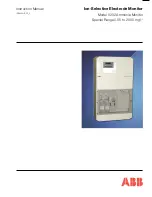
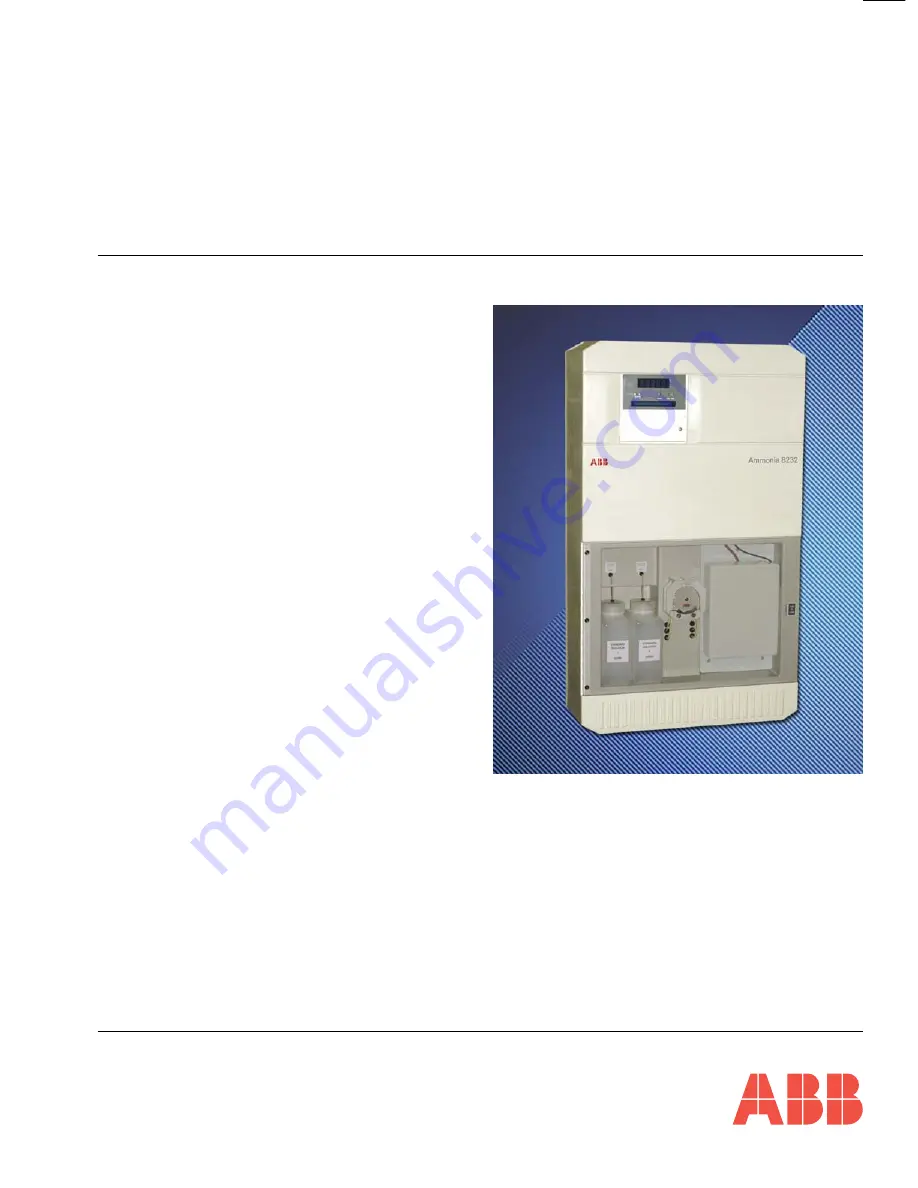
background image

Ion-Selective Electrode Monitor

Model 8232 Ammonia Monitor

Special Range 0.05 to 2000 mg l

–1

Instruction Manual

IM/8232–SO1_2

Summary of Contents for 8232

Page 1: ...Ion Selective Electrode Monitor Model 8232 Ammonia Monitor Special Range 0 05 to 2000 mg l 1 Instruction Manual IM 8232 SO1_2 ...

Page 2: ... these instructions must be read carefully before proceeding 2 Warning labels on containers and packages must be observed 3 Installation operation maintenance and servicing must only be carried out by suitably trained personnel and in accordance with the information given 4 Normal safety precautions must be taken to avoid the possibility of an accident occurring when operating in conditions of hig...

Page 3: ...6 2 11 Electrical Calibration Page 25 Section Page 7 CALIBRATION 28 7 1 Calibration Sequence 28 8 MAINTENANCE 29 8 1 Chemistry 29 8 1 1 Reagent Solutions 29 8 1 2 Standard Solutions 29 8 2 Scheduled Servicing 29 8 2 1 Regular Visual Checks 29 8 2 2 Four Weekly 30 8 2 3 Two Monthly 30 8 2 4 Twelve Monthly 30 8 2 5 Cleaning Sample Pipework 30 8 2 6 Consumables Spares Kit 31 8 2 7 Assembling Refurbis...

Page 4: ...rolling temperature and adjusting chemical composition prior to presentation of the sample to the point of measurement This monitor carries out these adjustments for each parameter in simple and easily understood steps The sample is presented from the user s pipework to a constant head unit and any excess is allowed to overflow This allows sample under controlled pressure conditions to be presente...

Page 5: ...d at the top of the flat panel to provide easy mounting on a wall or framework Two further fixing holes are provided at the bottom of the flat panel All holes are designed to take 8 mm bolts or studs Mains and signal cables are connected through cable glands in the User Junction Box on the right hand side with the exception of the optional serial interface which connects directly into the Micropro...

Page 6: ...of radio frequency interference r f i and correct operation of the power supply interference filter The external electrical connections are to be found in the User Junction Box with the exception of the optional serial interface which is connected directly into the Microprocessor Unit The cables are passed through the cable glands on the right hand side of the junction box which are adjacent to th...

Page 7: ...f the relay contacts can become eroded due to arcing Arcing also produces radio frequency interference r f i which can cause instrument malfunctions and incorrect readings To minimize the effects of r f i arc suppression components are required these are resistor capacitor networks for a c applications or diodes for d c applications These components can be connected either across the load or direc...

Page 8: ...controlled block requires up to half an hour to reach the normal control temperature During this time Temp Control Error is indicated on the display Any calibrations are prevented by the microprocessor during this time e Verify that there is an adequate supply of sample to the monitor constant head unit f Fit the pump platen on the peristaltic pumps see Section 8 2 8 and switch the pumps on with t...

Page 9: ...e connected as a pH measuring pair through an internal reservoir of filling solution containing ammonium ions The filling solution is 0 1 M ammonium chloride saturated with silver chloride and is separated from the sample by a gas permeable hydrophobic membrane fitted in the tip of the probe Sample is caused to flow past the probe membrane whereupon the partial pressures of ammonia gas in the two ...

Page 10: ...tential when exposed to the reacted sample which changes in proportion to changes in concentration of the ion being measured The probe is connected to the electronic section where after digital conversion the signal is processed by the microprocessor e After measurement the sample flows to waste via the contaminated drain connection f During calibration the monitor introduces two calibration solut...

Page 11: ...ote If the Hold facility is inadvertently left switched in it is automatically cancelled after a period of approximately 3 hours has elapsed Enter Used for storing the programmed function parameters and values in the instrument s nonvolatile memory Note The instrument responds instantly to any programme change but the new value is lost in the event of a power interruption if it has not been Entere...

Page 12: ...OP2 FSD OP2 Zero Test Output Zeros Test Output FSD Alter Sec Code Output SET UP ALARMS A1 Enabled A1 Action A1 Failsafe A1 Hysteresis A1 Delay A1 Setpoint A2 Enabled A2 Action A2 Failsafe A2 Hysteresis A2 Delay A2 Setpoint SET UP CLOCK Set Clock Set Year Set Month Set Day of Month Set Hours Set Minutes Cal Date Cal Time Cal Interval CALIBRATION mV Zero mV FSD Temp Zero Temp FSD Adjust Output 1 Zer...

Page 13: ...ages to be displayed Unauthorised entries to this page are inhibited by a 5 digit security code which is displayed immediately after the page header In the programming pages displayed values indicated xxxxx are for viewing only and cannot be altered by the operator Displayed values indicated can be altered using the and switches When the desired reading is displayed operate the Enter switch The l ...

Page 14: ...ntrol Temperature The heater block control temperature is displayed in degrees Celsius Advance to next parameter Slope Check Value The slope value should be between 80 and 110 If the value is outside these limits check the electrode Advance to next parameter Date The date is displayed Advance to next parameter Time The time is displayed Advance to next parameter Next Calibration Date The date when...

Page 15: ...tandard solution of lower concentration than 0 2 mg l 1 NH3 on this monitor Solutions as low as 0 2 mg l 1 can be prepared with care but must be used immediately making it an unsuitable concentration for long term use with the monitor Store Advance to next parameter Ion Standard 2 Set the value of the High standard solution Std 2 The concentrations of the two standard solutions must differ from ea...

Page 16: ... output is detected the display automatically advances to the next parameter Calibration Passed A satisfactory calibration has been carried out or Calibration Failed slope The monitor was unable to obtain an adequate slope value during calibration The slope value required is 80 to 110 or Calibration Failed slow The monitor was unable to obtain a stable output from the probe during calibration Retu...

Page 17: ...ay Type Ammonium Ammonia or Nitrogen Select display as ammonium NH4 ammonia NH3 or nitrogen N Store Advance to next parameter Ion Units Select the required display units for ammonia concentration Store Advance to next parameter Display Zero Set the required value for display within the range 0 05 to 20 00 Store Advance to next parameter Display Full Scale The full scale value is automatically set ...

Page 18: ...t YES or NO Store Advance to next parameter Output 1 Law Current Output 1 can be either logarithmic or linear Select Log or Lin Store Advance to next parameter Output 1 Full Scale Current Output 1 full scale range 0 5 to 2000 mg l 1 ammonia i e minimum span is 1 decade Set the required concentration value for Current Output 1 full scale Store Advance to next parameter Output 1 Zero Set the require...

Page 19: ... either logarithmic or linear Select Log or Lin Store Advance to next parameter Output 2 Full Scale Current Output 2 full scale range 0 5 to 2000 mg l 1 ammonia i e minimum span is 1 decade Set the required concentration value for Current Output 2 full scale Store Advance to next parameter Output 2 Zero Set the required concentration value for Current Output 2 zero Note If the Output 2 Law is line...

Page 20: ...ale The instrument automatically transmits a current output full scale test signal on both outputs Example For a 4 to 20 mA current output range 20 mA is transmitted Advance to next parameter Alter Security Code Set the Security Code required between 0 and 19999 This value must then be entered again to access the secure parameters from Operating Page 1 Store Advance to next parameter Proportional ...

Page 21: ...red select Yes otherwise select No see Table 6 1 Store Advance to next parameter Alarm A1 Hysteresis A differential set point can be set as a percentage of the set point value The differential setting operates about the set point Example A 5 differential setting operates 2 5 above and below the setpoint Select the differential required between 0 and 5 in 1 increments Store Advance to next paramete...

Page 22: ... l F f f O w o L S E Y t n i o p t e S e v o b A t n i o p t e S w o l e B d e s i g r e n E d e s i g r e n e e D f f O g n i h s a l F w o L O N t n i o p t e S e v o b A t n i o p t e S w o l e B d e s i g r e n e e D d e s i g r e n E f f O g n i h s a l F 6 PROGRAMMING Table 6 1 Relay Action and Alarm Indication 6 2 6 Set Up Alarms Page Continued from Previous page A1 Setpoint Set the require...

Page 23: ...Up Real Time Clock Select Yes to set up the clock otherwise select No Store Advance to next parameter Set Year Set the appropriate year Store Advance to next parameter Set Month Set the appropriate month Store Advance to next parameter Set Day Set the appropriate day of the month Store Advance to next parameter Set Hours Set the appropriate hour 24 hour clock Store Advance to next parameter Contin...

Page 24: ...econds Set the appropriate seconds Store Advance to next parameter Calibration Date day of the month Set the day of the month when the first automatic calibration is to be carried out Store and advance to next parameter Calibration Date month Set the month when the first automatic calibration is to be carried out Store and advance to next parameter Calibration Date year Set the year when the first...

Page 25: ...libration is to be carried out Store and advance to next parameter Calibration Interval Set the calibration interval required between automatic calibrations starting from the calibration date 6 hours 12 hours or 1 to 7 days in 1 day increments Store Return to top of Set Up Clock Page or Advance to Calibration User Code Page 6 2 8 Calibration User Code Page The calibration user code is required to ...

Page 26: ... switching off the instrument and switch on again If there is thought to be any risk that the original programme could be lost it is advisable to make a note of the normal parameter settings If the changed programme values are inadvertently Entered the instrument can be reprogrammed on completion of the calibration procedure Equipment Required Millivolt source range 400 to 400 mV Electrode coaxial...

Page 27: ...t Full Scale Set the millivolt source to 400 mV Set the display to 400 mV Store New value is accepted only when input is stable Advance to next parameter Temperature Zero Set the resistance box to 96 09 Ω resistive equivalent of 10 C Set the display to 10 C Store New value is accepted only when input is stable Advance to next parameter Temperature Full Scale Set the resistance box to 142 29 Ω resi...

Page 28: ...r a 4 to 20 mA output range 20 mA is transmitted Set the milliammeter reading to the current output 1 full scale level i e 1 mA 10 mA or 20 mA as applicable Store Advance to next parameter Adjust Current Output 2 Zero The monitor transmits a zero signal e g for a 4 to 20 mA output range 4 mA is transmitted Set the milliammeter reading to the current output 2 zero level i e 0 mA zero based ranges o...

Page 29: ...e 2 The displayed value is preset at the factory and must not be altered See Table 7 1 Advance to next parameter Calibration Time 3 The displayed value is preset at the factory and must not be altered See Table 7 1 Advance to next parameter Alter Calibration Code The calibration user code inhibits access to the Set Up Temperature Control Page and the Calibration Page see Section 6 2 8 Set a suitab...

Page 30: ...oncentrations For example if the range of sample concentrations is expected to be 5 to 10 ppm then standards of 2 and 20 ppm could be used see Section 8 1 2 concerning low concentration ammonia standards Note The concentrations of the two standard solutions must differ from each other by a factor of at least four On initiation of the calibration sequence either manual or automatic the Cal l e d is...

Page 31: ...tic avoid contact with the skin and eyes If contact occurs wash with plenty of clean water 8 1 2 Standard Solutions Two standard solutions of known concentration appropriate to the measuring range are required for calibration of the monitor To prepare a stock solution of 10 000 mg l 1 follow instructions below a Ammonia as N Dissolve 38 21 0 01 g analytical reagent grade ammonium chloride NH4 Cl d...

Page 32: ...tenance programme is introduced rather than wait for visible signs of the presence of algal growth Note Once growth is visible the problem is already serious The recommended agent for cleaning tubing and pipework is sodium hypochlorite solution containing about 0 1 1000 mg l 1 available chlorine Cleaning Solution To prepare 500 ml of cleaning solution dilute 5 ml of concentrated sodium hypochlorit...

Page 33: ...bling Refurbishing the Probe The ammonia probe is a gas sensing combination electrode assembly It is supplied in kit form and must be assembled or refurbished using one of the appropriate procedures below Refurbishing a Dismantle the probe and rinse off the filling solution with dimineralised water b Remove the membrane from the end cap and retain the sealing washer use a new washer if it is damag...

Page 34: ... edge of the probe end cap into the drain recess as shown k Replace the cover on the temperature controlled block l Connect probe lead to the coaxial socket above the temperature controlled block 8 2 8 Peristaltic Pump Fig 8 2 It is recommended that the pump tubing and pump capstans supplied in the Consumable Spares Kit are replaced after one year of operation Carry out the following procedure 1 t...

Page 35: ...three new capstans from the kit on the hexagonal shaft so the rollers are offset from one another Fit retaining screw If required fit new pump tube bungs and shims from the kit to the left hand side of the pump Pass new pump tubes from the kit through the tube bungs and case grommets Connect to the appropriate tube connector at the rear of the case Note The bungs are designed to grip the pump tube...

Page 36: ...g it to its original position thus allowing fresh filling solution to flow between it and the membrane If this procedure is not successful replace the membrane and filling solution If the probe is likely to be out of use for more than one day remove from the monitor and store with the lower part of the body immersed in a small quantity of liquid in a beaker or other suitable vessel 0 1M ammonium c...

Page 37: ... 7 j b Clean membrane by washing with a jet of clean water from a wash bottle or syringe c Check and top up as necessary the filling solution in the probe There should be a 50 to 60 mm depth inside the probe so that the reference element is immersed in the solution d Osmotic effects i e total concentration of dissolved species in samples too high e Puncture of the membrane usually visible disassem...

Page 38: ...e the electrode to the same depth in the 25 nitric acid until the silver element is a uniform creamy white This process usually takes about 1 minute but the element must be inspected frequently as prolonged immersion is detrimental c If the element is not uniform in colour repeat the ammonia nitric acid process d When clean rinse with distilled water and immediately transfer to the plating solutio...

Page 39: ...face Optional second current output or RS422 RS423 serial interface Alarms Two high or low concentration alarms Remote calibration mode indication Remote monitor OUT OF SERVICE indication Remote OUT OF SAMPLE indication All voltage free 250 V 5 A noninductive changeover relay contacts Concentration Alarm Adjustment Programmable over range Concentration Alarm Differential 0 to 5 Concentration Alarm...

Page 40: ...t t o b t n e g a e r H O a N 1 9 6 2 2 3 2 8 l i o c r e x i M 2 1 2 2 0 3 2 8 y l b m e s s a r e n i a t n o c n o i t u l o s d r a d n a t S h g i H 1 0 2 2 0 3 2 8 y l b m e s s a r e n i a t n o c n o i t u l o s d r a d n a t S w o L 1 0 1 7 3 6 0 8 r e k n i s e b u t r e n i a t n o C 4 4 1 5 4 1 2 0 m m 6 t e l n i e l p m a s r o t c e n n o c e s o H d i 1 6 2 5 4 1 2 0 m m 9 n i a r ...

Page 41: ... the right hand side 1 2 3 APENDIX A REPLACING SOFTWARE EPROM Fig A 1 Procedure to Open the Enclosure Fig A 2 Procedure to Access the Processor PCB Warning Switch off the monitor and electrically isolate it before carrying out the following steps A 1 Access the Transmitter Unit Fig A 1 Caution Employ normal antistatic precautions while handling chips and PCBs Caution To avoid damaging EPROM base o...

Page 42: ...ns IC1 IC11 IC3 IC2 IC5 IC4 BAT1 1 APPENDIX A Fig A 3 Procedure to Remove the PCB Fig A 4 Replacing the Software EPROM A 3 Removing the PCB Fig A 3 A 4 Changing the EPROM Fig A 4 A 5 Completing the Procedure 1 Fit the PCB using the reverse procedure in Fig A 3 Important Note Ensure that the washers are fitted between the PCB cover and the PCB 2 Close the microprocessor section using the reverse pr...

Page 43: ...ation pH Conductivity and Dissolved Oxygen Transmitters and Sensors Ammonia Nitrate Phosphate Silica Sodium Chloride Fluoride Dissolved Oxygen and Hydrazine Analyzers Zirconia Oxygen Analyzers Katharometers Hydrogen Purity and Purge gas Monitors Thermal Conductivity Customer Support We provide a comprehensive after sales service via a Worldwide Service Organization Contact one of the following off...

Page 44: ...ained herein without notice Printed in UK 01 07 ABB 2007 ABB Limited Oldends Lane Stonehouse Gloucestershire GL10 3TA UK Tel 44 0 1453 826661 Fax 44 0 1453 829671 ABB Inc 125 E County Line Road Warminster PA 18974 USA Tel 1 215 674 6000 Fax 1 215 674 7183 ABB has Sales Customer Support expertise in over 100 countries worldwide www abb com ...

Reviews: