


User Guide IM/4690–EN Rev. A
4690 Series
Turbidity systems
Accurate, reliable turbidity
measurement
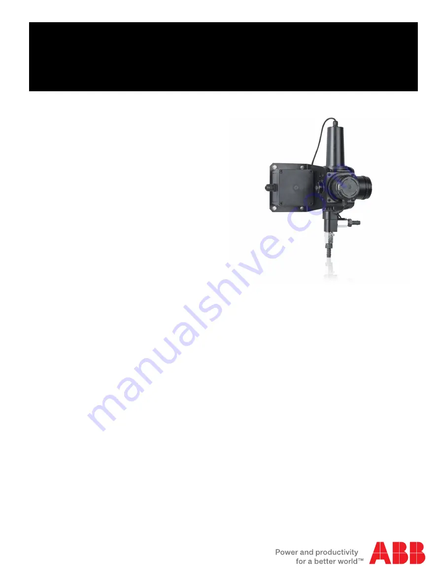
Introduction
An ABB Turbidity system comprises a 4690 / 4695 analyzer
and a 7998 turbidity sensor.
The analyzer provides the operator interface and
communications to other devices.
The signal from the turbidity sensor is converted by the
analyzer and the information is presented on a large,
custom-designed, easy-to-read, backlit liquid crystal display
(LCD).
The analyzer can be programmed to work with any of the 7998
series sensors and the operating range can also be configured
to meet users' requirements.
Available in wall- / pipe-mount or
1
/
4
DIN panel-mount versions,
the analyzer is protected to IP66, ensuring reliable operation in
the most demanding situations. The same level of protection is
maintained during programming and calibration.


