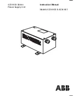
background image

4234 600 Series
Power Supply Unit

Instruction Manual

Models 4234 600 & 4234 601

Summary of Contents for 4234 600

Page 1: ...4234 600 Series Power Supply Unit Instruction Manual Models 4234 600 4234 601 ...

Page 2: ...rational conditions result in degraded process system performance leading to personal injury or death Therefore comply fully with all Warning and Caution notices Information in this manual is intended only to assist our customers in the efficient operation of our equipment Use of this manual for any other purpose is specifically prohibited and its contents are not to be reproduced in full or part ...

Page 3: ...rviceable parts Two identical fuses L N are mounted within the unit on the mains input A third fuse is connected in the d c line circuit of the transformer A fourth fuse is connected in the auxiliary 10 V d c line The L N fuses are a high breaking capacity type and must only be replaced with identical types See Section 2 for rating 1 INTRODUCTION Fig 1 1 Location of Internal Component TB1 T1 L N E...

Page 4: ...terconnecting cable 2 Ω max Ambient Temperature Range 20 to 55 C 2 SPECIFICATION Permissible Supply Voltage Variation 15 Frequency Range 46 to 64 Hz Output Regulation Within 0 8 for a Load variation 15 b Supply variation 6 c Ambient temperature 10 C Ripple Less than 17 5 mV across 10 Ω load peak to peak Stability Within 0 7 of initial setting over a period of one month with load resistance supply ...

Page 5: ...ore commencing installation check that the unit supplied is suitable for the supply voltage available see Section 2 and the data plate on the unit cover Fig 3 2 140 CTRS 110 CTRS 170 111 120 All holes 7 0 diameter 160 83 20 20 30 30 30 60 DIM Ensure a clearance of at least 100 mm at both ends of the unit for acces to the cable glands and to minimise cable bends Mains Cable Entry Output to Temperat...

Page 6: ...nections for typical gas analysis systems 4 1 1 Katharometer Connections Cable connecting the constant current d c supply from the PSU to the katharometer should be selected so that the maximum cable resistance is less than 2 ohms This limits the maximum cable length between the katharometer and its associated PSU Note that the cable gland will accept a cable between 5 to 9 mm in diameter 4 1 2 Te...

Page 7: ... assembly when supplies are connected Thus there is a risk of electrocution All normal precautions must be taken to avoid the risk of accidental electrical shock during installation and maintenance of the equipment Ensure that the supply cable is disconnected at its source before touching any electrical connections Caution Ensure that the correct version of the unit has been supplied for the suppl...

Page 8: ...Centre or returned to the factory for repair Fig 5 1 Changing Fuses TB1 T1 L N E F2 F3 6 8 10 230 V 115 V TB2 F1 B A C X D E F4 AUX 10V Switch off and disconnect the mains supply 1 2 Remove the four screws and lift off the cover Replace fuse s 3 Note Suitable fuses may be obtained from ABB with the following part numbers F1 0231555 400 mA cartridge F2 F3 0231577 250 mA 1500 A hbc cartridge F4 0231...

Page 9: ...7 NOTES ...

Page 10: ...8 NOTES ...

Page 11: ...al Analytics Instrumentation pH conductivity and dissolved oxygen transmitters and sensors ammonia nitrate phosphate silica sodium chloride fluoride dissolved oxygen and hydrazine analyzers Zirconia oxygen analyzers katharometers hydrogen purity and purge gas monitors thermal conductivity Customer Support ABB Ltd provides a comprehensive after sales service via a Worldwide Service Organization Con...

Page 12: ...ained herein without notice Printed in UK 01 02 ABB 2002 ABB Ltd Oldends Lane Stonehouse Gloucestershire GL10 3TA UK Tel 44 0 1453 826 661 Fax 44 0 1453 827 856 ABB Inc 2175 Lockheed Way Carson City NV 89706 USA Tel 1 0 775 883 4366 Fax 1 0 775 883 4373 ABB has Sales Customer Support expertise in over 100 countries worldwide www abb com ...

Reviews: