
In addition to what is explained below, the safety and installation information provided in the
installation manual must be read and followed. The technical documentation and the interface
and management software for the product are available at the website.
The device must be used in the manner described in the manual. If this is not the case the
safety devices guaranteed by the inverter might be ineffective.
Quick installation guide
4000/7200-WIND-INTERFACE-EU
PVI-7200-WIND-INTERFACE
ABB generator interfaces
1.
Labels and Symbols
W
ind box Models and Components
2.
Lifting and transport
4.
EN
Assembly Instruction
6.
List of supplied components
3.
Choice of installation location
5.
Block diagram of the wind power system
7.
8.
Intended use
The 4000/7200-WIND-INTERFACE is a passive rectifier designed to transform AC current from a wind turbine permanent magnet generator into a continuous
(DC) current to be input to one or more ABB inverters, and for connection to diversion (dump) resistors. The WIND-INTERFACE does not supply a safety
system for the wind turbine.
Limits on use
The inputs of the rectifier may be connected only to a wind-turbine, not to batteries or other sources of power.
The WIND-INTERFACE must be used only within its technical specifications and ratings.
The labels on the Wind box have the Agency marking, main technical data and identification of the equipment and manufacturer
The labels attached to the equipment must NOT be removed, damaged, dirtied, hidden,etc...
If the service password is requested, the field to be used is the serial number -SN: YYWWSSSSSS-
In the manual and/or in some cases on the equipment, the danger or hazard zones are indicated with signs, labels, symbols or icons.
Always refer to instruction
manual
General warning - Important
safety information
Hazardous voltage
Hot surfaces
IP65
Protection rating of
equipment
Temperature range
Without isolation
transformer
Direct and alternating
currents, respectively
Positive pole and negative
pole of the input voltage
(DC)
Always use safety clothing
and/or personal safety
devices
Point of connection for
grounding protection
Time need to discharge
stored energy
10
01
Wind interface model
02
Principal technical data
03
Part Number
04
Week/Year of manufacture
05
Serial Number
The model of the generator interface to which this guide refers is 4000/7200-WIND-INTERFACE-EU and PVI-7200-WIND-INTERFACE.
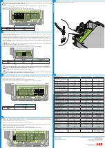
Main components
01
Tachometer output
teminal block
05
DC output terminal
block
09
Tachometer output cable inlet
02
Three phase input
terminal block
06
Front cover
10
Diversion (dump) load cable
inlet
03
Diversion (dump) load
terminal block
07
Heat sink
11
DC output cable inlet
04
Ground connection
screw
08
Three phase cable
inlet
12
Diversion load activation LED
Transport and handling
Transport of the equipment, especially by road, must be carried out with by suitable ways and means for protecting the components from violent shocks,
humidity, vibration, etc.
Lifting
The means used for lifting must be suitable to bear the weight of the equipment.
Unpacking and checking
The components of the packaging must be disposed on in accordance with the regulations in force in the country of installation.
When you open the package, check that the equipment is undamaged and make sure all the components are present. If you find any defects or damage, stop
unpacking and consult the carrier, and also promptly inform the Service ABB.
Equipment weight
Model
Mass weight
4000-WIND-INTERFACE-EU
7200-WIND-INTERFACE-EU
PVI-7200-WIND-INTERFACE
< 1.8 Kg/4.0lb
Environmental checks
-Consult the technical data to check the environmental parameters to be observed
-Installation of the unit in a location exposed to direct sunlight must be avoided as it may cause:
1. premature wear of the electrical/electromechanical components
2. premature wear of the mechanical components (gaskets)
-Do not install in small closed rooms where air cannot circulate freely
-
To avoid overheating, always make sure the flow of air around the inverter is not blocked
-
Do not install in places where gases or flammable substances may be present
-Do not install in rooms where people live or where the prolonged presence of people or animals is expected, becau-
se of the noise (about 50dB(A) at 1 m) that the Wind-Interface makes during operation
Installations above 2000 metres
On account of the rarefaction of the air (at high altitudes), particular conditions may occur:
-
Less efficient cooling and therefore a greater likelihood of the device going into derating because of high internal
temperatures
-Reduction in the dielectric resistance of the air that, in the presence of high operating voltages (DC input), can
create electric arcs (discharges) that can reach the point of damaging the Wind-Interface
All installations at altitudes of over 2000 metres must be assessed case by case with the ABB Service department.
Installation position
-
Install on a wall or strong structure capable of bearing the weight of the equipment
-Install in safe, easy to reach places
-If possible, install at eye-level so that the display and status LEDs can be seen easily
-
Install at a height that considers the heaviness of the equipment
-Install vertically with a maximum inclination of +/- 5°
-Choose a place with enough space around the unit to permit easy installation and removal of
the object from the mounting surfaces; comply with the indicated minimum distances
-For a multiple installation, position the inverters side by side; if the space available does not
allow this arrangement, position the inverters in a staggered arrangement as shown in the
figure so that heat dissipation is not affected by other inverters
Final installation of the Wind-Interface must not compromise access to any disconnec-
tion devices that may be located externally.
Please refer to the warranty terms and conditions available on the website and evaluate
any possible exclusion due to improper installation.
Wall/Pole mounting
During installation, do not place the Wind-interface with its front facing
towards the ground.
-
Position the Wind-Interface so that it is perfectly level on the wall and use it as
a boring template.
-
Make the 4 holes required, using a drill with a 10 mm diameter bit. The depth of the
holes should be about 30 mm.
-
Secure the Wind-Interface to the wall using the four provided bolts and screws.
Check the stability of the Wind-Interface
- Unscrew the four screws and open the frontal cover in order to make all
necessary connections
-
Once the connections have been made, close the cover by tightening the 4
screws on the front to a minimum tightening torque of 1.5 Nm.
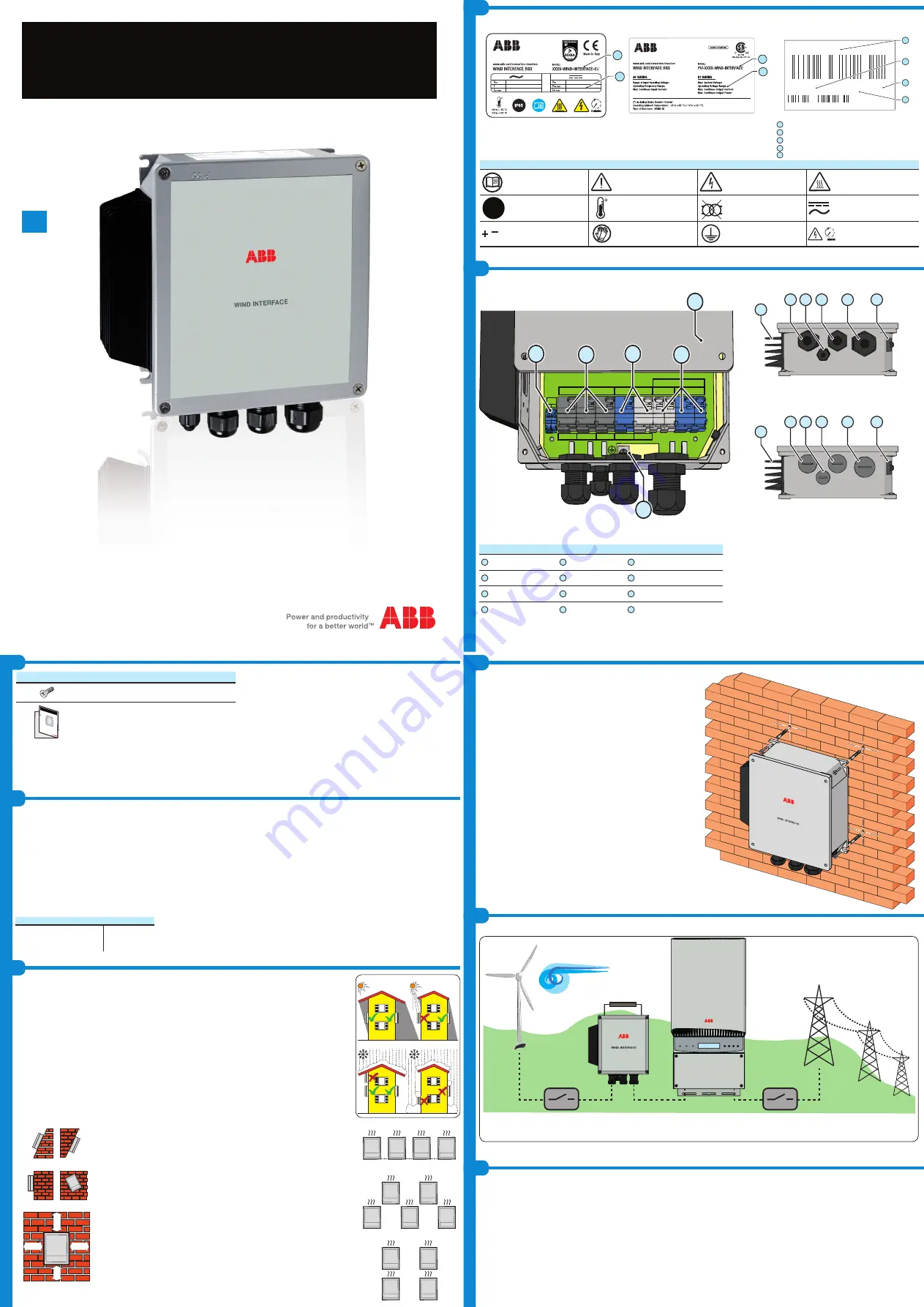
The following is a block diagram of a wind power system comprising the 7200-WIND-INTERFACE-EU rectifier.
AC Switch S1
Wind Turbine
AC Switch S2
Diversion (dump) resistor (opt.)
Available components
Quantity
M6 screw
4
In additio
n to what
is explain
ed in this
guide, th
e safety a
nd installa
tion inform
ation pro
vided in th
e installat
ion manu
al must be
read and
followed
.
The techn
ical docu
mentation
and the in
terface an
d manage
ment softw
are for th
e product
are availa
ble at the
website.
XXXXX
XXXXX
XXXXXX
XXX
XXXX
XXXXXXX
XXXX
XXXX
ABB sola
r inverter
s
Technical documentations
1
NO
NO
OK
NO
20 cm
20 cm
20
cm
20
cm
OK
OK
NO
WIND INPUT
1
2
3
BRAKE
BULK OUT
+
-
WIND
SPEED
+ -
+
-
01
04
02
05
03
06
07
08 09 10
11
12
07
08 09 10
11
12
01
02
01
02
XXXX-WIND-INTERFACE-EU
P/N:PPPPPPPPPPP
SO:SXXXXXXXX Q1
SN:YYWWSSSSSS WK:WWYY
01
03
04
05


